4. Computer controlled cutting
Assignment
group assignment:
characterize your lasercutter’s focus, power, speed, rate, kerf, joint clearance and types
individual assignment:
cut something on the vinylcutter
design, lasercut, and document a parametric construction kit, accounting for the lasercutter kerf, which can be assembled in multiple ways, and for extra credit include elements that aren’t flat
Dxf Files
Fusion (f3d) file
Parametric file on fusion (.f3d) (beware changing parameters can challenge your computer)
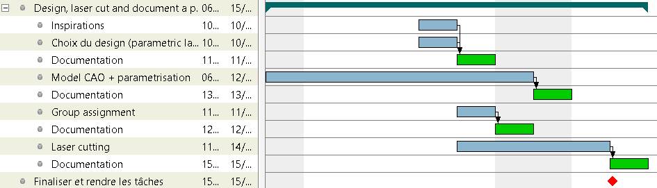
Gantt plan of the week
Vinyl cutter
First tests
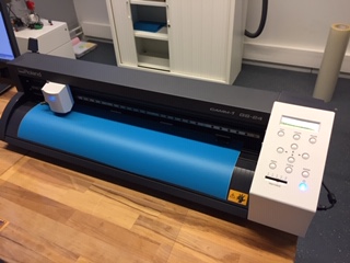
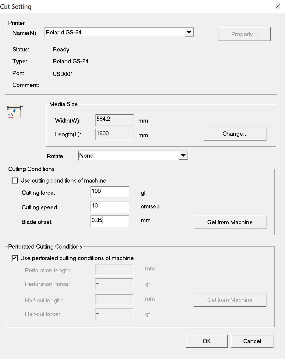
Vinyl cutting machines are quite simple, ready to use machines. The one from Fablab Digiscope is a Roland CAMM-1 GS-24.
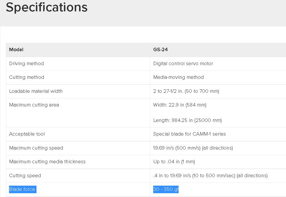
There is a few parameters to play with such as setting the force (ranging from 30 to 350 gf for this machine), offset of the blade and the type of blades :
-
25° blades for thick materials
-
45° blades for standard materials
-
60° blades for small characters
I looked to the specifications for the maximum force I could use :
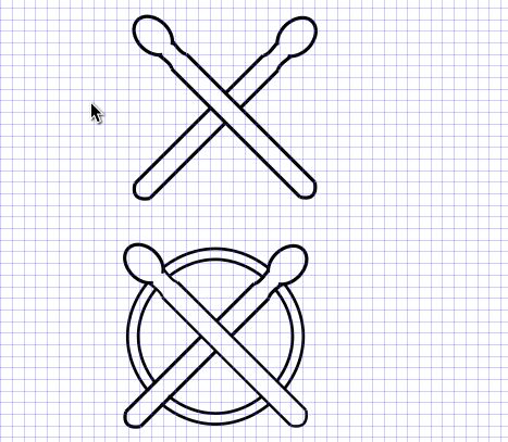
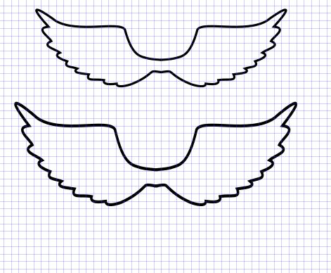
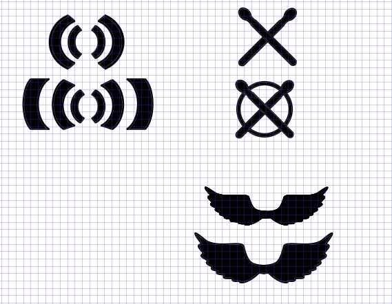
For the first try, I’m going to cut drawings I made last week in Inkscape :
| SoundWave | Drumsticks | Wings |
|---|---|---|
 |
 |
 |
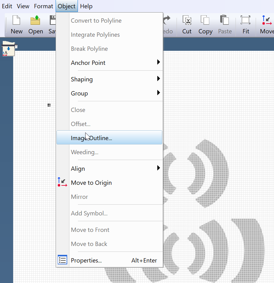
The formats usable by Cutstudio are BMP, JPG, STX, AI and EPS. Here, I exported them in JPG.
Then, in Object -> Outline the image, click on extract the contour line :
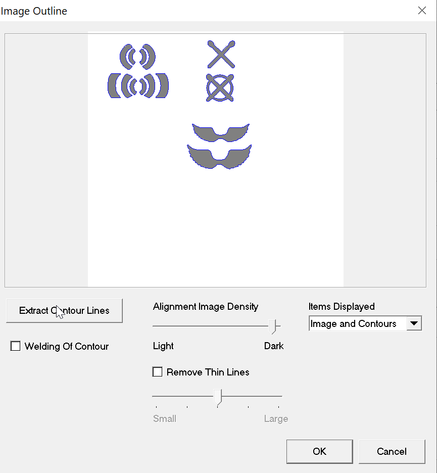
This is what I obtained :

But not what I wanted. I want only the outer contour, so I filled the image in Inkscape :
| Filled drawing | Contour line extracted |
|---|---|
 |
 |
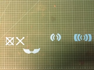
Here is the result of my printing :

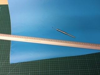
To remove the print, there is a needle tip tool :
So I made a series of stickers which will eventually be used for marking the frets on a guitar :
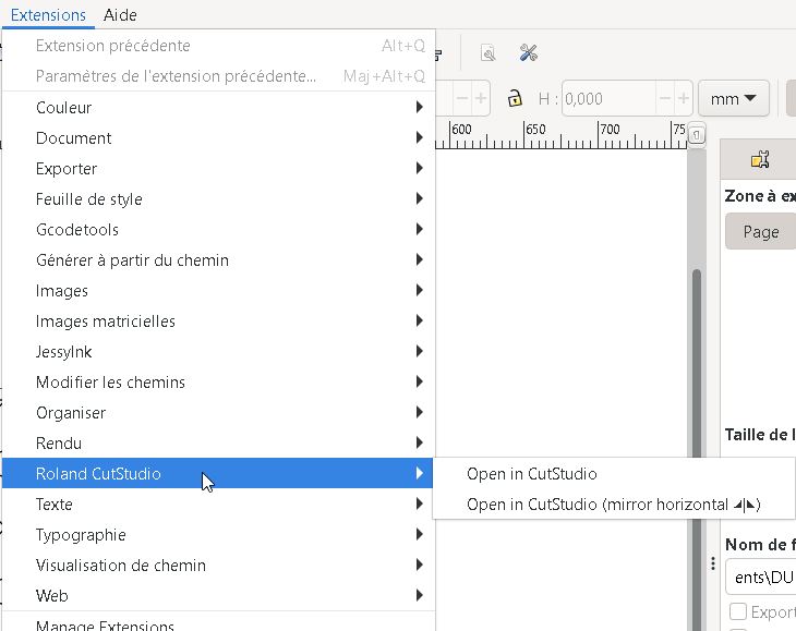
Using the Cutstudio extension in Inkscape
You can install an extension in Inkscape which will directly convert your vector file from Inkscape to Cutstudio.
Download it from Github

Then copy all the roland_* files in the following repo : C:\Program Files\Inkscape\share\inkscape\extensions\
Then go in Extensions -> Roland Cutstudio -> open in Cutstudio
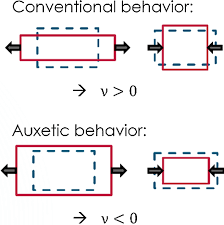
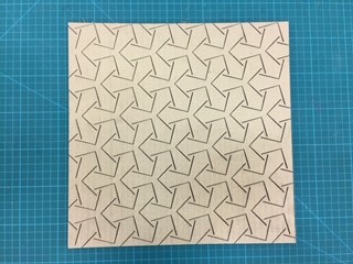
Test of auxetic materials
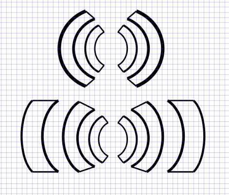
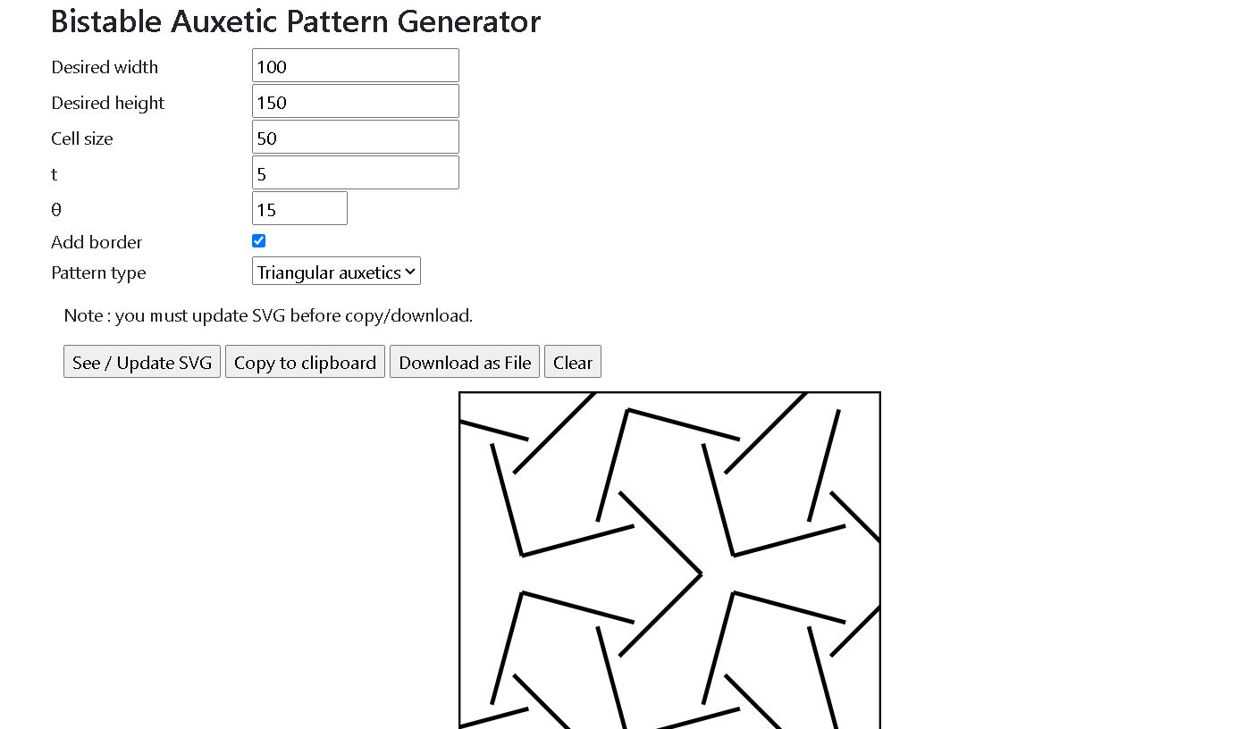
I made another test with a Kirigami of an auxetic material. Auxetic materials are strange ones : when we pull on opposite sides of a material, it expands in the direction perpendicular of the force instead of retracting :
I used a generator of pattern from this fabacademy site
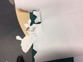
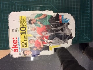
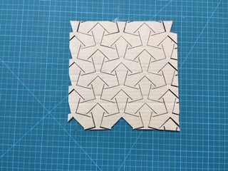
I made a first try on paper but I made the mistake to cut it without sticking it to a surface :
So I tried with a more rigid paper maintained by double side scotch tape.
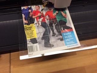
As a side note I don’t have anything against guitar heroes ! It will be just a scratch…
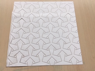
The material here is more rigid and with previous settings the blade didn’t cut through. So I changed the force from 70 to 100 gf in Cutstudio :
Didn’t work either cause the tape was too sticky and it was impossible to remove…
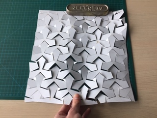
Someone told me in the Saturday Global Open Time session to try with weakly glued mats. I’ll give it a go if I find one.
Laser cutting
Laser cutter machines allow to either cut through materials or to burn it with raster images.
Choosing the right material
The choice of material is important when considering laser cutting. Always check if the material is compatible.
Wood, cardboard or acrylic are the most common but thin layer of copper or composite materials can be burned too.
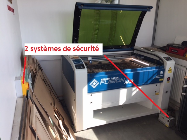
Security is primordial
Always activate the 2 security systems :
How to use it
First, position the calibrating tool (CO2 cutting or fiber cutting need different calibration distance):
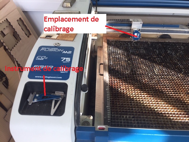
Then, lay the calibrating tool against the tray with the arrows on the display. Define the origin and click on the controller to confirm origin.
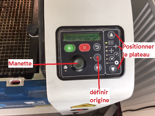
Then set up your drawing on the software. We use Corel Draw here in Fablab Digiscope. Make sure to select hairline for the line width.
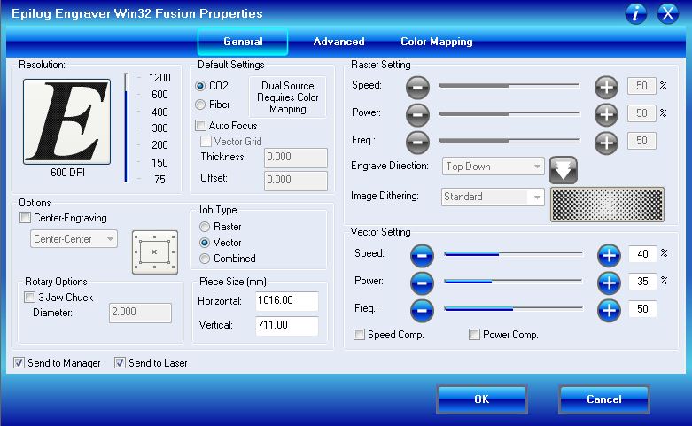
Selecting the good parameters
There are 3 parameters to modify depending of the material and operation you do :
-
Speed : The slower, the better will be the cut
-
Power : More power will mean better cut but too much power can burn down materials more than you would like
-
And frequency
The manual offer a parameter cheatsheet for most used materials :
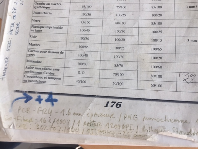
Select vector for cutting through wood and cardboard and raster to wear out copper.
Click on apply then print
Good practices
-
Always verify formats and lengths
-
Be careful of the hierarchy of the lane to avoid cutting a piece which could fall before another one -> break curve apart
-
Before beginning the cutting, verify the actual dimensions of the cut on the material by hitting the play button when the door is open -> the head of laser will still move but the laser will not be activated
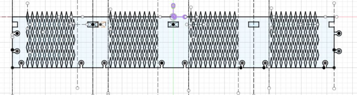
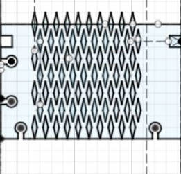
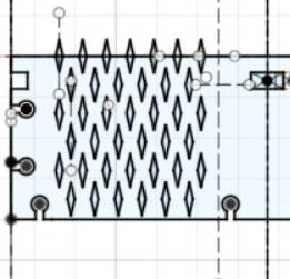
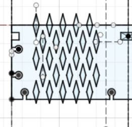
Tests with Auxetics materials
Auxetic materials catched my eyes and I will make further tests with the laser cutter.
With cardboard :
First I made a test with a square with the following settings :
I had the following results with 3 passes :
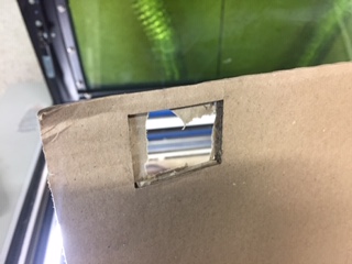
3 passes was not enough but 4 passes with 35/50/50 for speed/power/frequency ratio made a good cut.
| 6mm cardboard | 3mm cardboard |
|---|---|
 |
 |
With paper
Mechanical results with cardboard were not satisfying, so I tried with 250g A3 paper :
I had better results but I’ll need to test with rubber paper :
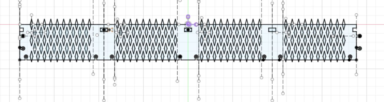
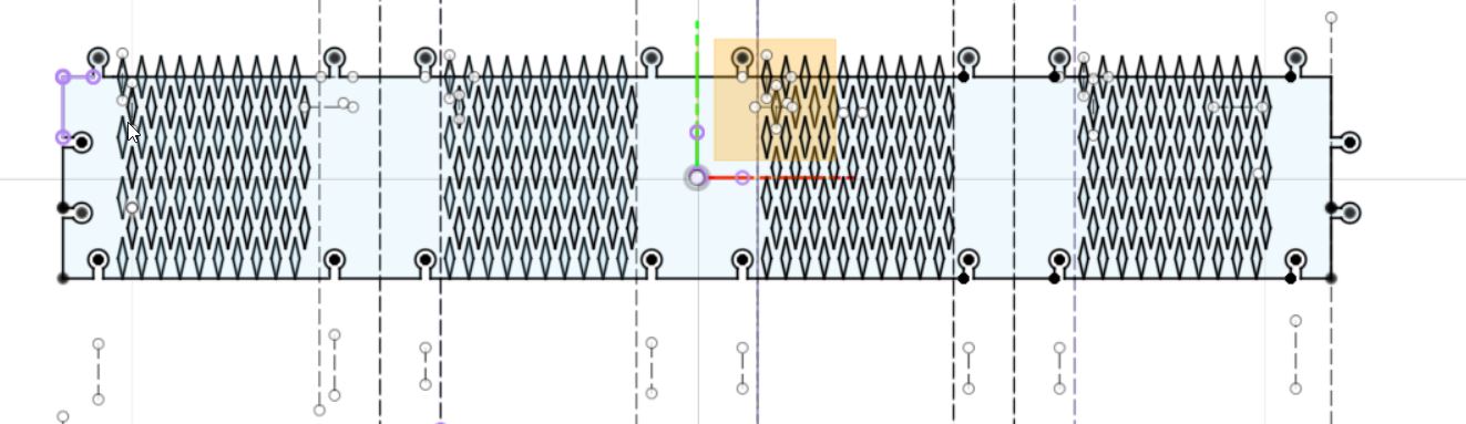
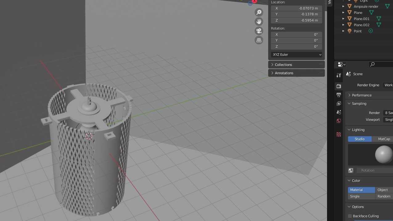
Parametric + modular design
In this part, I’m going to make a parametric design of a lampshade.
I was teaching assistant in a Digital fabrication class and made a presentation about living hinges which you can see in the tutorial section. The final assignment for students is to design a lampshade with cardboard and the laser cutter.
My initial idea is to make it look like a lantern :
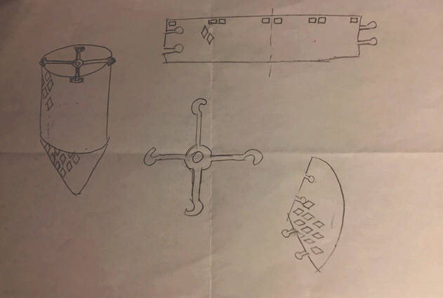
I’m going to use living hinges to make the lamp round and joints to make the modular part
What parameters ?
-
Height of the lampshade
-
Diameter
-
width of the living hinge pattern
-
height of the living hinge pattern
-
X and Y distance between each diamond shape
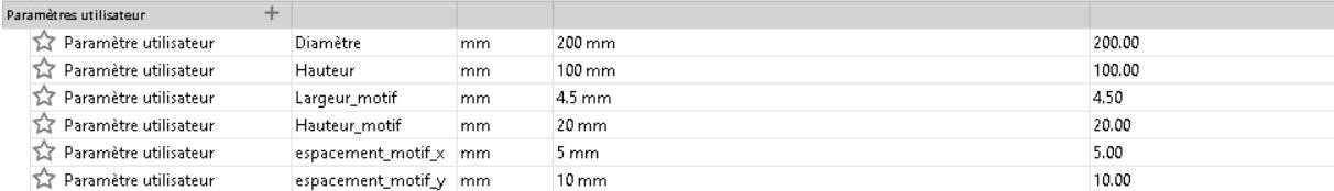
Here are the parameters set in Fusion 360 :
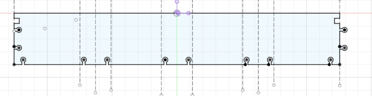
For the top part, the number of joints increases with the height :
| Height of 100 mm | Height of 150 mm |
|---|---|
 |
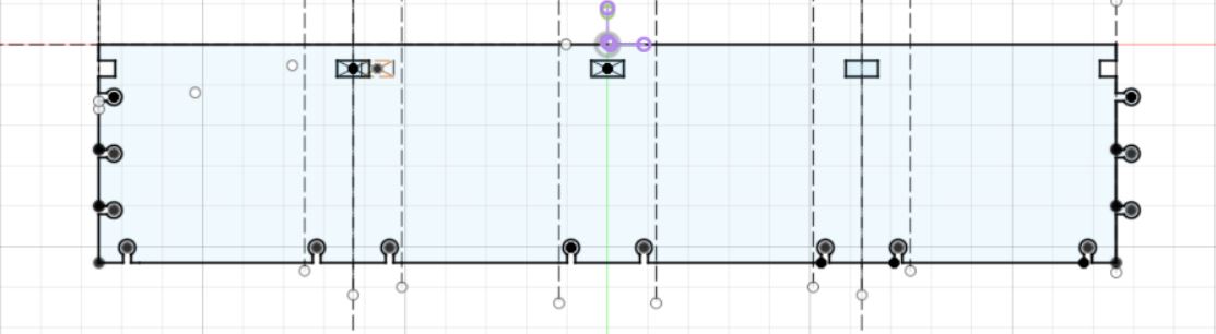 |
and used the following parameters :

I found the ceil function useful here to always round the number of diamond to the next highest whole number. This is to have the pattern of the hinge overlap with the edges of the part.
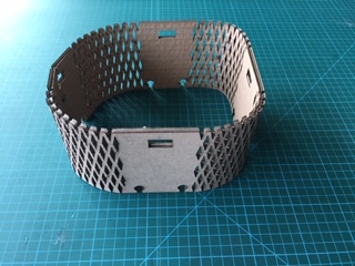
Finally, the top part looks like this :
Parameters in image :
| Spacing X = 5mm, Y = 10 mm | X = 10 mm, Y = 15 mm |
|---|---|
 |
 |
| width of the shape 4.5 mm, Height 20 mm | Width = 8 mm, Height = 30 mm |
|---|---|
|
 |
| Diameter of the lampshade 200 mm | Diameter of 300 mm |
|---|---|
|
 |
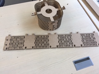
Modular Design :
For the modular part, I’m adding layers with joints :
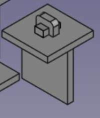
Lamp holder
For the holder, I changed the initial design of a hook joint for a wedge type joint
| Wedge joint | Lamp holder with wedge joint |
|---|---|
 |
 |
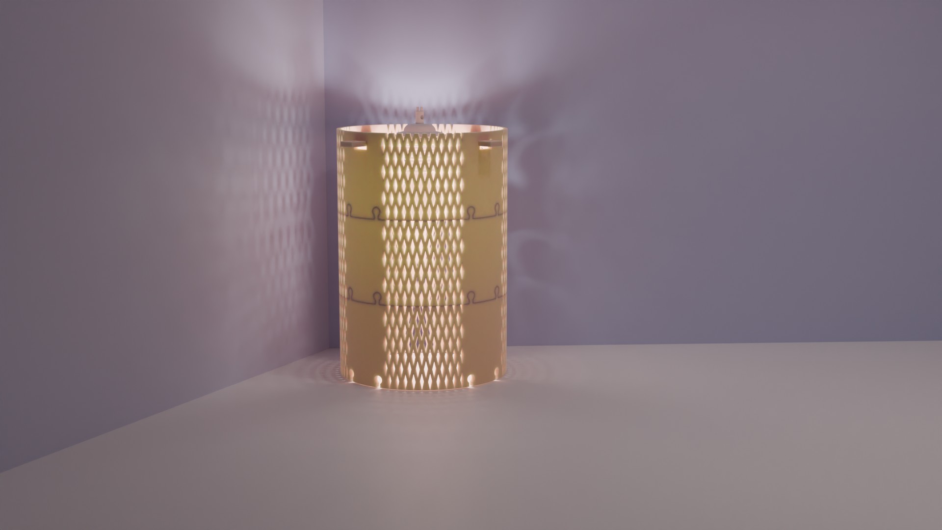
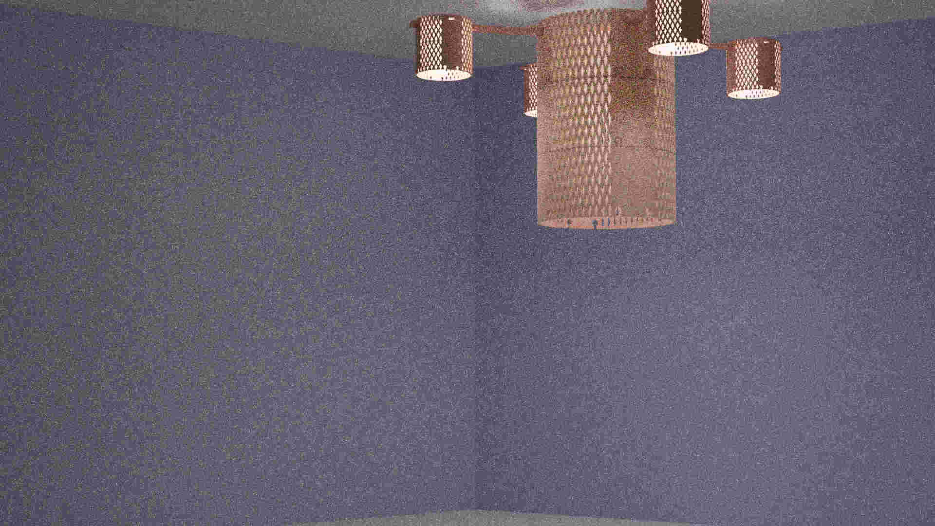
Render
I made a rendering with blender to show the modularity of the design :
We can do a floor lamp :
Or a chandelier :
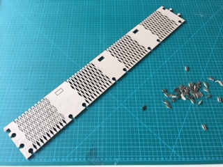
Laser cutting the parts
Top part :
I made another one with a different size. But one piece started to burn down. I stopped the laser cutting machine and remove the hot piece immediately :
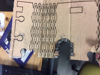
I don’t know what started the smoke because I used the same settings as before. So I changed the power from 50 to 45.
Here are the final pieces :
And the assembly
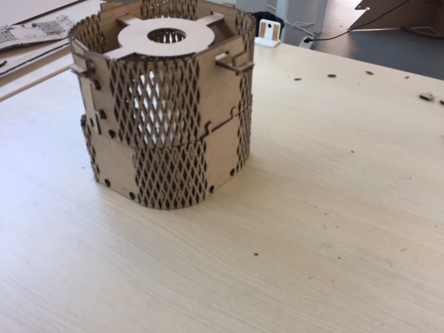
The joints are not working perfectly beacuse of the constraints. Press fit joints may work better but I didn’t have the time to test it.
Also, the wedge type joints are useless here because the dimensions I drew are not correct. (I considered the shape as a circle while it’s more a square with round angles)
Group assignment
characterise the power and speed for raster
To characterise the power and speed of the machine, I used the color mapping function in the printing properties. To each color is assigned a specific power and speed.
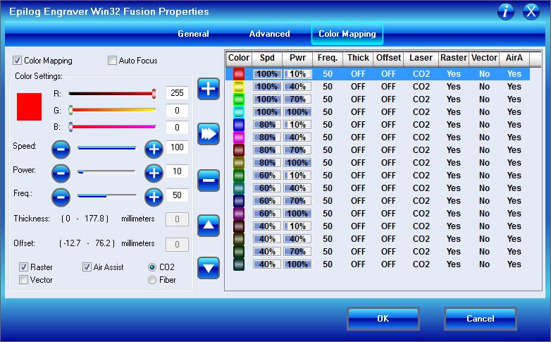
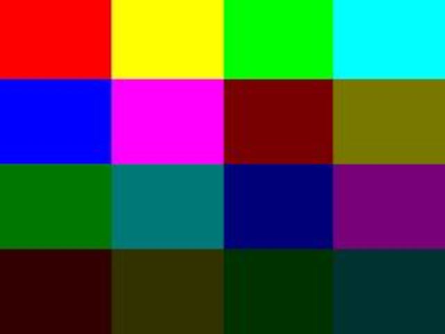
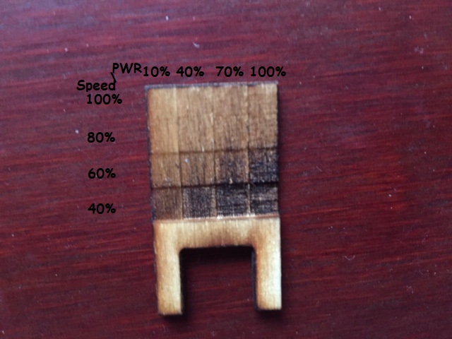
The power ranges from 10% to 100% in the X axis and the speed ranges from 100% to 40% in the Y axis
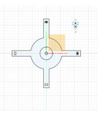
Characterise the kerf
To characterise the kerf, I used a calliper to measure the cut made :
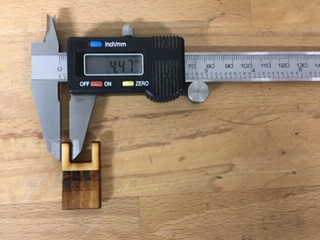
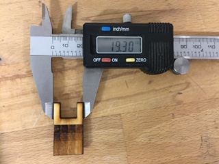
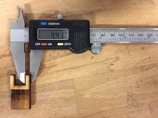
The initial width from Corel Draw is 20 mm and each leg are 5 mm wide. ->The offset is between 0.7 mm and 0.53 mm. So each line have between 0.35 to 0.26 offset.