16. Wildcard week
assignment
Design and produce something with a digital fabrication process (incorporating computer-aided design and manufacturing) not covered in another assignment, documenting the requirements that your assignment meets, and including everything necessary to reproduce it.
Files :
Voice recognition arduino library
case of the LEDs (.stl file)
back of the case (.stl file)
Research
This week I plan to make something with machine learning.
Definition of machine learning :
It’s a technology which allow machines to learn something without being specifically programmed for it before. It digs into a big amount of data (BigData) to be able to recognize patterns and tendencies.
 It reminds me Lucy becoming a super-organic-computer (in the eponym movie from Luc Besson) collecting an incredible amount of data to “understand” the origin of the universe and existence.
I’ll be using Eddge Impulse. I found this tutorial which I plan to follow to start.
graph LR
    A{Data collection} -->B[Processing data]
    B --> C(Building model)
    C --> D[Training]
    D --> E[Testing]
Edge Impulse
install python 3 + node.js
create an account in edge impulse
Implementing datasets
need 4 datasets : left, right, noise and others
download data sets :
google speech commands obtained from Github
- noise datasets (from keywords spotting): 1536 files
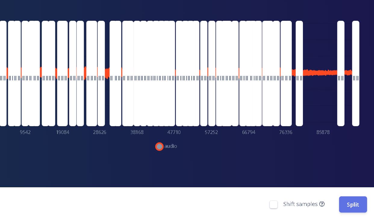
background noise (from google speech commands): 7 files Here the datasets were 1min 30 sec long so I split the data into segments of 1sec each (adding around 250 files):
- left : 3801 files
- right : 3778 files
- others : I’m mixing a few files from other speech commands : 3278 files
We have to choose the percentage of data we split between training and testing 80%/20% is the default :

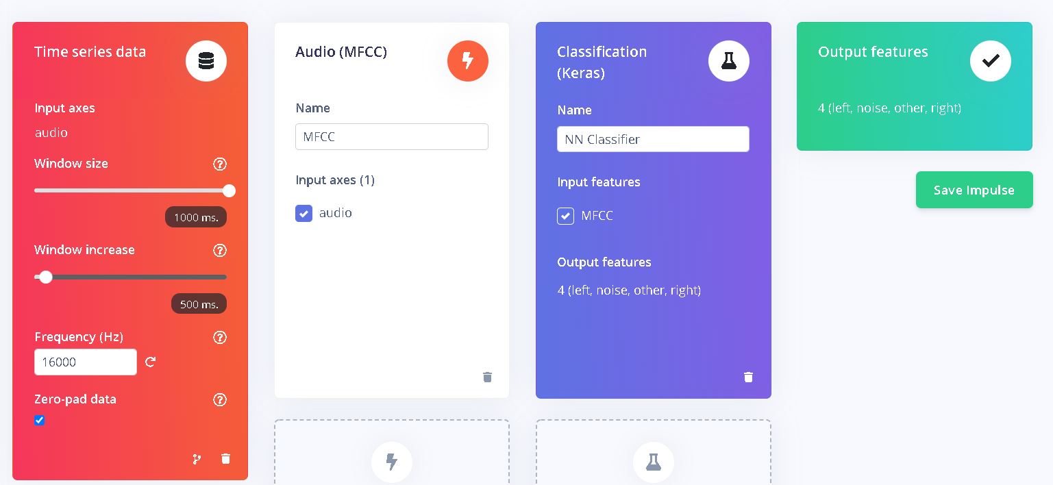
Design an Impulse
Click on Add Time series data block with a 1000ms window. Then add a preprocessing block (Audio MFCC) which is more suitable for voice recognition.
Then the tutorial recommends to add a learning block with classification (Keras). Transfer learning (keyword spotting) may be a good block to add in the future for fine tuning.
MFCC preprocessing block
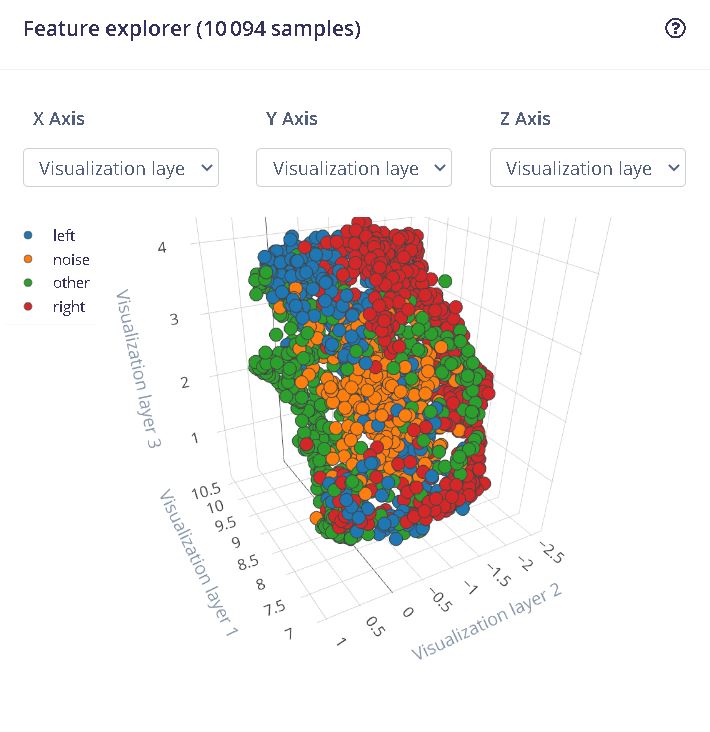
This block creates a simplified form of data. Under impulse design on the left panel, click on it and generate an impulse :
When the job is done, we can see the result on a 3D representation of the dataset : The less the colours are mixed the better for machine learning :
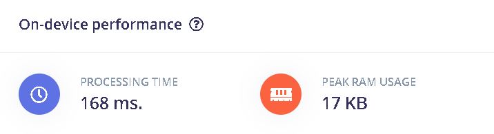
And below, we can see the prediction of RAM usage for the micro controller :
NN classifier learning block
This block creates algorithms which allow to recognize patterns in the data :
In the neural networks setting, click on data augmentation -> add noise : high
Here, we can see the visualization of the model and the accuracy :
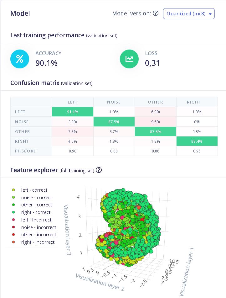
Test the model
In model testing, click on classify all. This will use the 20% left of the data to test the model :

83% accuracy seems good enough for now.
Deployment
After choosing Arduino library, click on Build in the deployment tab to create the library
Testing the program
I’m testing the program with an Arduino nano 33 ble sense and using the example “nano_ble_sense_microphone_continuous” from the library voice_recognition_inferenceing.h (it’s the library downloaded from the Edge Impulse project).
After downloading the program to the board, I opened the monitor and had this result :
| “right” word pronounced | “left” word pronounced |
|---|---|
 |
 |
Understanding the program
We can change the value of the gain for the microphone. The base value is 20 which is increased here to 127 db.
// set the gain, defaults to 20
PDM.setGain(127);
Two libraires are needed : The PDM.h for the microphone and the one created with Edge Impulse
#include <PDM.h>
#include <Voice_recognition_inferencing.h>
You can change the number of slices per model window. In this case the window is 1000 ms and the number of slices is set to 3 for a slice size of 333 ms. Increasing the slice size can increase the fiability but too many slices can result in a overload of the buffer.
* Define the number of slices per model window. E.g. a model window of 1000 ms
* with slices per model window set to 4. Results in a slice size of 250 ms.
* For more info: https://docs.edgeimpulse.com/docs/continuous-audio-sampling
*/
#define EI_CLASSIFIER_SLICES_PER_MODEL_WINDOW 3
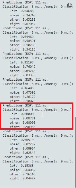
The following lines print in the monitor the predictions for the classification between left, right, noise and other. The function result.classification[ix].value will be used in the next part to activate the LEDs according to the result of the prediction.
if (++print_results >= (EI_CLASSIFIER_SLICES_PER_MODEL_WINDOW)) {
        // print the predictions
        ei_printf("Predictions ");
        ei_printf("(DSP: %d ms., Classification: %d ms., Anomaly: %d ms.)",
            result.timing.dsp, result.timing.classification, result.timing.anomaly);
        ei_printf(": \n");
        for (size_t ix = 0; ix < EI_CLASSIFIER_LABEL_COUNT; ix++) {
            ei_printf("    %s: %.5f\n", result.classification[ix].label,
                      result.classification[ix].value);
        }
Activating RGB LEDs to the voice
To activate RGB LEDs, add the following lines in the void setup() :
pinMode(LEDR, OUTPUT);
pinMode(LEDG, OUTPUT);
pinMode(LEDB, OUTPUT);
pinMode(LED_BUILTIN, OUTPUT);
digitalWrite(LED_BUILTIN, LOW);         // when the central disconnects, turn off the LED
digitalWrite(LEDR, HIGH);               // will turn the LED off
digitalWrite(LEDG, HIGH);               // will turn the LED off
digitalWrite(LEDB, HIGH);                // will turn the LED off
`void loop() section
if  (result.classification[0].value >= 0.5){
        // Serial.println("Red LED on");
         digitalWrite(LEDR, LOW);            // will turn the LED on
         digitalWrite(LEDG, HIGH);         // will turn the LED off
         digitalWrite(LEDB, HIGH);         // will turn the LED off
       }
}
else if (result.classification[1].value >= 0.9) {
        //Serial.println("Green LED on");
digitalWrite(LEDR, HIGH);         // will turn the LED off
digitalWrite(LEDG, LOW);        // will turn the LED on
digitalWrite(LEDB, HIGH);        // will turn the LED off
}
else if (result.classification[3].value >= 0.8) {
  //  Serial.println("Blue LED on");
    digitalWrite(LEDR, HIGH);         // will turn the LED off
    digitalWrite(LEDG, HIGH);       // will turn the LED off
    digitalWrite(LEDB, LOW);         // will turn the LED on
  }
}
else {
//Serial.println(F("LEDs off"));
digitalWrite(LEDR, HIGH);          // will turn the LED off
digitalWrite(LEDG, HIGH);        // will turn the LED off
digitalWrite(LEDB, HIGH);         // will turn the LED off
}
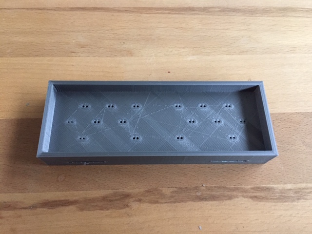
Creating a case for signal turn
The goal of this project is to make a turn signal for bikes. I already used this casing in previous weeks but I’m going to detail here how I made it :
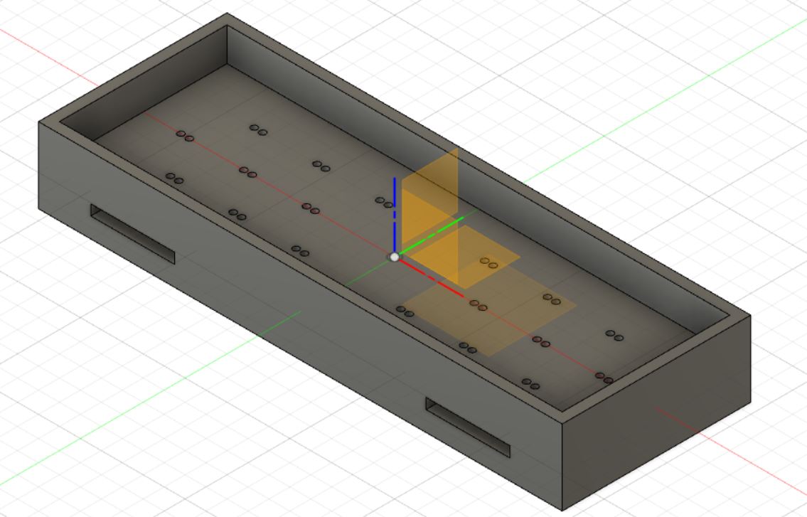
Drawing on Fusion 360
The case holds 18 LEDs :
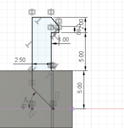
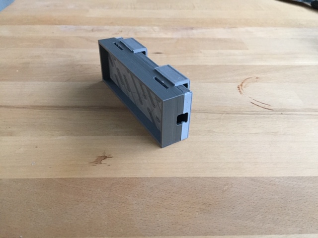
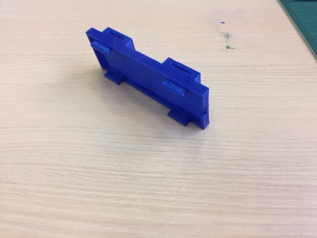
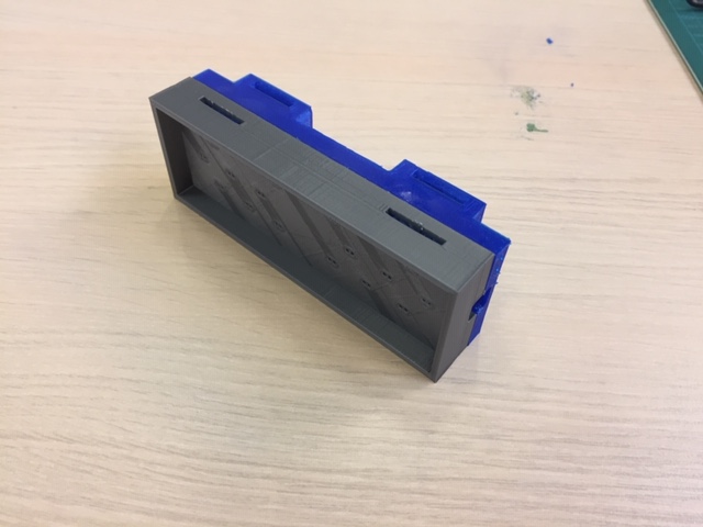
Designing snap fit joints
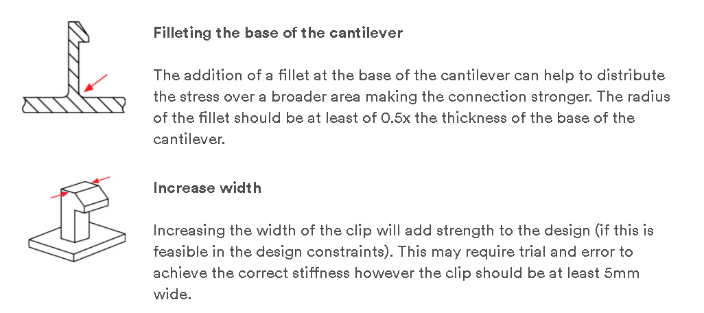
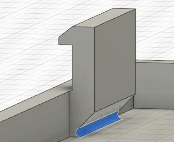
The goal is to use the less glue and screw possible, so I made snap fits joints between 2 parts of the case. I checked a few design rules on the internet for snap fit. These following website were useful : How to design snap-fit joints for 3D printing and How to Design and 3D Print Snap-Fit Enclosures
First and 2nd design rules : Fileting the base of the cantilever and increase width
| Design rules | Fileting the base |
|---|---|
 |
 |
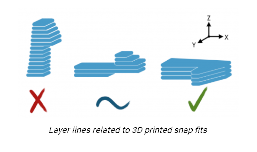
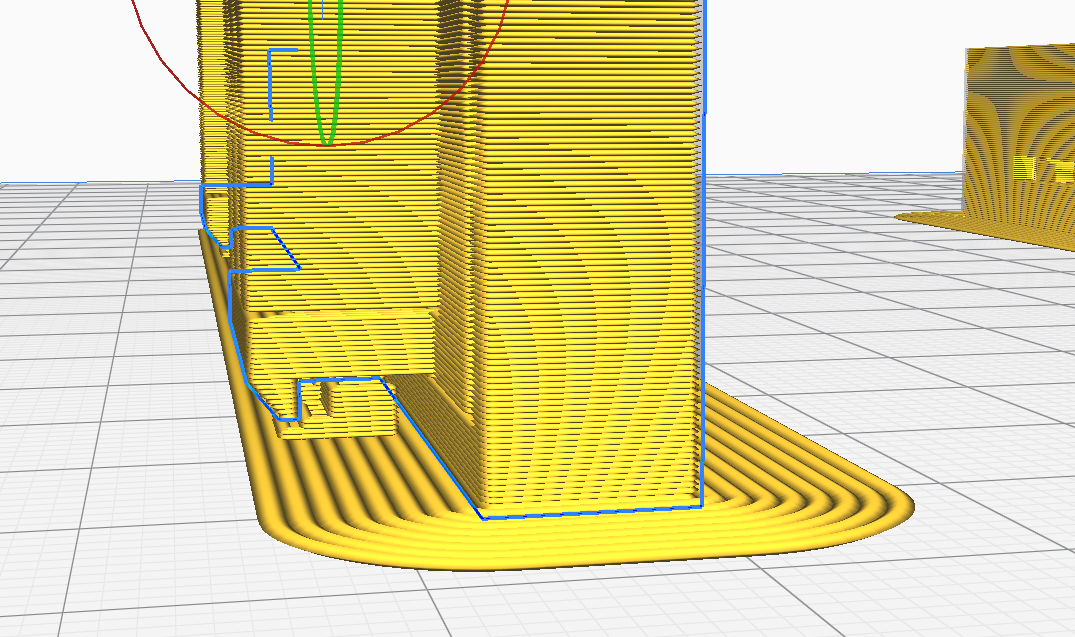
Third design rule : Orientation of the layer
| Design rule | Slicing in Ultimaker | Result |
|---|---|---|
 |
 |
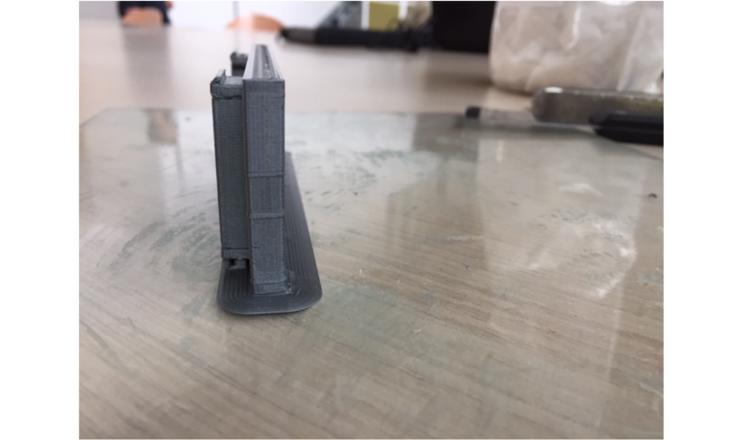 |
For the rule above, I chose the 2nd orientation layer which is not the best for the strength of the cantilever joint. The third one would require to print the piece vertically which would require more supports.
Here is the first print which is made of PLA. The snap fit joint works but the dimensions of the holes for the legs of the LEDs were too small :
| 1st test with a 0.8mm head | Enclosure for the 1st test |
|---|---|
 |
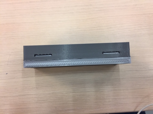 |
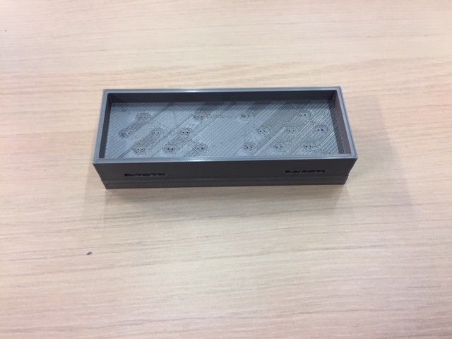
I made a 2nd iteration with a 0.4 mm head for better precision and holes of 1.5mm diameter instead of 1mm for the legs of the LEDs. I also shorten the small protrusion engaging into the snap cavity (the “hooves”) to make it easier to assemble :
| 2nd test with a 0.4mm head | Enclosure for the 2nd test |
|---|---|
 |
 |
I made another iteration with TPU 95A filament which is much more flexible than PLA. It should be better for snap fit enclosures when we need to open it often. For TPU I need to lengthen the “hooves” since it’s less sturdy.
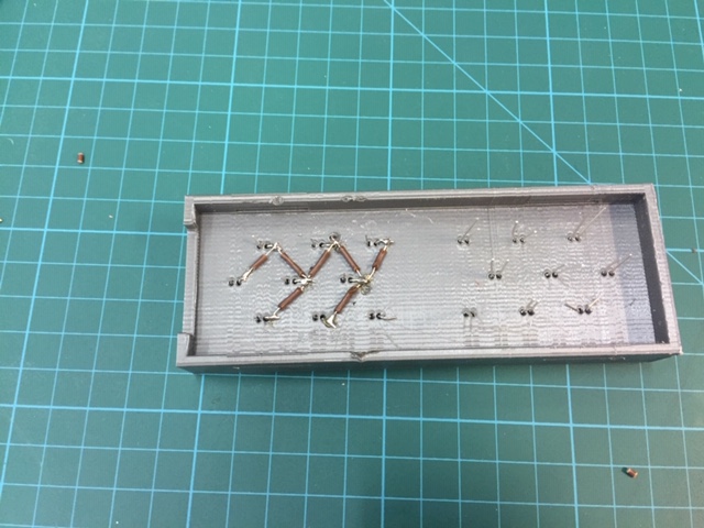
Soldering the components on the case
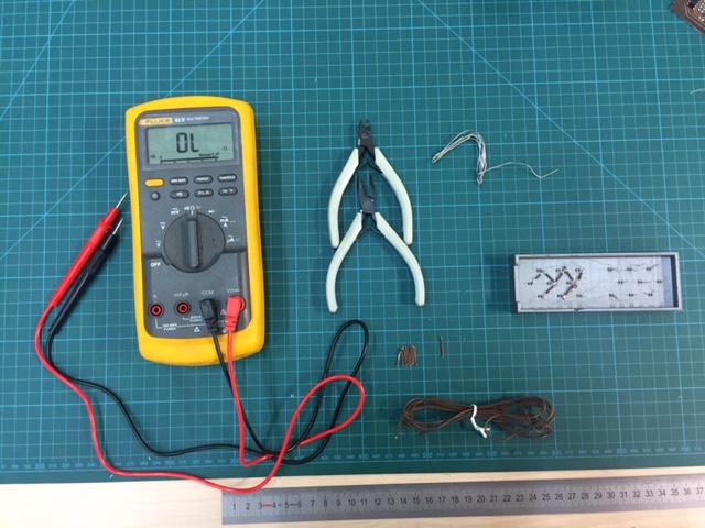
First step I soldered the GND of LEDs :
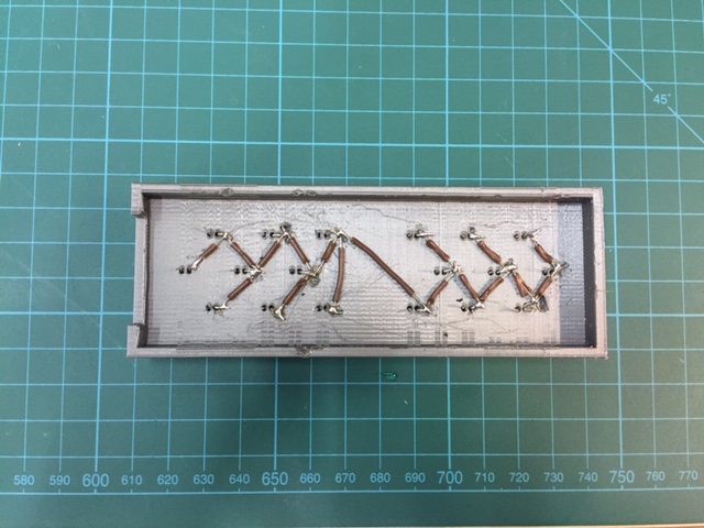
Then, the rest of the wires :
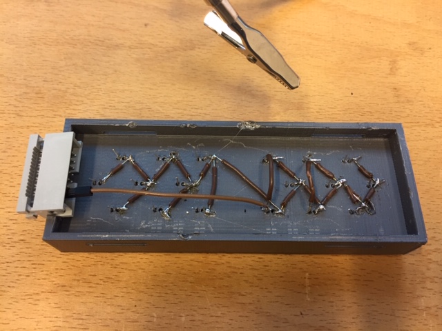
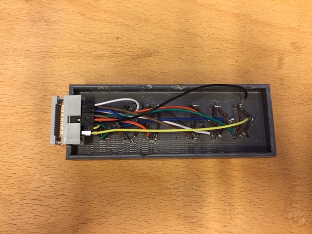
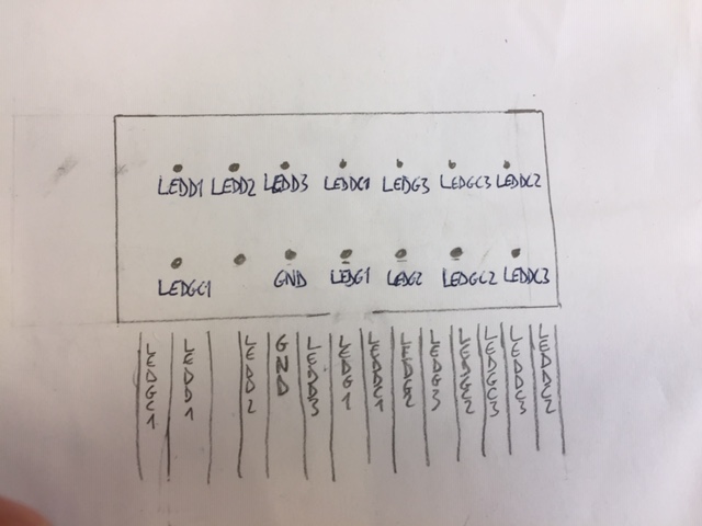
Here is a pinout diagram of the connector :
Programming the LEDs of the case
Add the following lines to initialise the pins. 12 pins are used to controll 18 LEDs (6 pins are controlling 2 LEDs each) :
#define LEDDC3 5
#define LEDDC2 12
#define LEDDC1 9
#define LEDGC3 11
#define LEDGC2 4
#define LEDGC1 1
#define LEDG3 10
#define LEDG2 3
#define LEDG1 2
#define LEDD3 8
#define LEDD2 7
#define LEDD1 6
And the following lines to the void setup() :
pinMode(LEDDC3, OUTPUT);
pinMode(LEDDC2, OUTPUT);
pinMode(LEDDC1, OUTPUT);
pinMode(LEDGC2, OUTPUT);
pinMode(LEDGC3, OUTPUT);
pinMode(LEDG2, OUTPUT);
pinMode(LEDG3, OUTPUT);
pinMode(LEDD3, OUTPUT);
pinMode(LEDD2, OUTPUT);
digitalWrite(LEDDC3, LOW);
digitalWrite(LEDDC2, LOW);
digitalWrite(LEDDC1, LOW);
digitalWrite(LEDGC2, LOW);
digitalWrite(LEDGC3, LOW);
digitalWrite(LEDG3, LOW);
digitalWrite(LEDG2, LOW);
digitalWrite(LEDG1, LOW);
digitalWrite(LEDD2, LOW);
digitalWrite(LEDD3, LOW);
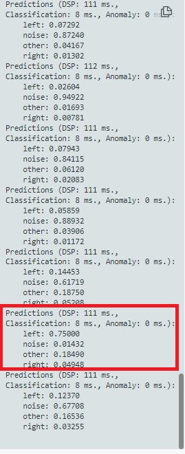
And add the lines written in the void loop() with the following code. I set the detection value for the left at 50% accuracy and for the right at 80% accuracy. This is because the accuracy for the left word is weaker than the right word (it may change from one model to another) :
if  (result.classification[0].value >= 0.5){      // Blink the left LEDs if the word left has been detected
           // Serial.println("Red LED on");
            digitalWrite(LEDR, LOW);            // will turn the LED on
            digitalWrite(LEDG, HIGH);         // will turn the LED off
            digitalWrite(LEDB, HIGH);         // will turn the LED off
            for (int t=0; t<5; t++){
              digitalWrite(LEDDC3, HIGH);
              digitalWrite(LEDDC2, HIGH);
              digitalWrite(LEDDC1, HIGH);
              digitalWrite(LEDD2, HIGH);
              digitalWrite(LEDD3, HIGH);
              delay(500);
              digitalWrite(LEDDC3, LOW);
              digitalWrite(LEDDC2, LOW);
              digitalWrite(LEDDC1, LOW);
              digitalWrite(LEDD2, LOW);
              digitalWrite(LEDD3, LOW);
              delay(500);
            }
        }
        else if (result.classification[2].value >= 0.9) {   // other words detected
                      //Serial.println("Green LED on");
            digitalWrite(LEDR, HIGH);         // will turn the LED off
            digitalWrite(LEDG, LOW);        // will turn the LED on
            digitalWrite(LEDB, HIGH);        // will turn the LED off
        }
        else if (result.classification[3].value >= 0.8) {   // Blink the right LEDs if the word right has been detected
          //  Serial.println("Blue LED on");
            digitalWrite(LEDR, HIGH);         // will turn the LED off
            digitalWrite(LEDG, HIGH);       // will turn the LED off
            digitalWrite(LEDB, LOW);         // will turn the LED on
            for (int t=0; t<5; t++){
              digitalWrite(LEDGC2, HIGH);
              digitalWrite(LEDGC3, HIGH);
              digitalWrite(LEDG3, HIGH);
              digitalWrite(LEDG2, HIGH);
              digitalWrite(LEDG1, HIGH);
            delay(500);
              digitalWrite(LEDGC2, LOW);
              digitalWrite(LEDGC3, LOW);
              digitalWrite(LEDG3, LOW);
              digitalWrite(LEDG2, LOW);
              digitalWrite(LEDG1, LOW);
            delay(500);
            }
        }
        else {
            //Serial.println(F("LEDs off"));
            digitalWrite(LEDR, HIGH);          // will turn the LED off
            digitalWrite(LEDG, HIGH);        // will turn the LED off
            digitalWrite(LEDB, HIGH);         // will turn the LED off
        }
Choice of battery
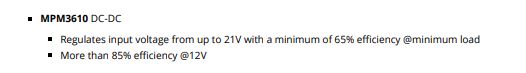
The arduino nano 33 ble sense works in 3.3V. The USB has a regulator which needs a minimum input of 4.5 V and a maximum of 21 V

Possibilities
-
Adding a battery of 5V without regulator
-
Battery of 3.7V (the board would need to be powered through headers)
-
lithium Battery of 3V (same as above)
-
Battery of 9V
Choice of LEDs : LED of 5mm of 2500 mcd for typical luminosity (to be seen in the daylight)
Calcul of circuit consumption :
According to the LED data sheet : 60 mW of power dissipation -> for 18 LEDs in 10 sec : 3 mWh (18 * 10 * 60 / 3600) Let’s say 20 turns in 30 min -> 60 mWh
The average consumption of the arduino nano 33 ble sense is 166 mW according to this blog. Which makes 84 mWh for 30 min.
So we have a consumption of 144 mWh in a 30 min ride. For a lithium battery of 3V and 225 mAh, it’s about 4 or 5 rides.
For a USB battery of 5V and 2000 mAh, it’s about 70 rides. And it’s rechargeable. I made the choice to use the external battery Essentielb 2000 mAh from Boulanger.