7. Electronics design
Assignment
group project:
use the test equipment in your lab to observe the operation of a microcontroller circuit board
individual project:
redraw an echo hello-world board, add (at least) a button and LED (with current-limiting resistor) check the design rules, make it, and test that it can communicate extra credit: simulate its operation
Eagle files :
Drawing Hello board
I plan to draw the Attiny45 Hello board :
Design rules :
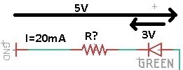
- To add a led I need a resistor so I chose it using the ohm’s law. So I need a 100 ohm resistor :

-
Size of the components : SMD 1206
-
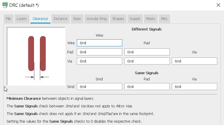
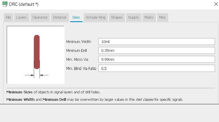
Space between the traces : For the minimum dimensions, I used the ones set in the Electronic production week : 6 mils minimum for space between traces and 16 mils (10 mils minimum) for the width :
List of components I will need :
-
Attiny45
-
Resistor 1 kohm
-
Resistor 10 kohm x2
-
Resistor 100 Ohm
-
Blue led
-
2x3 pin header
-
6x1 pin header
-
Switch
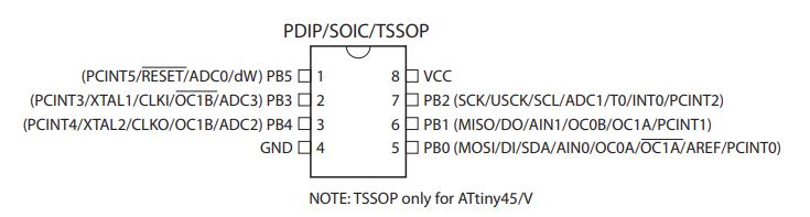
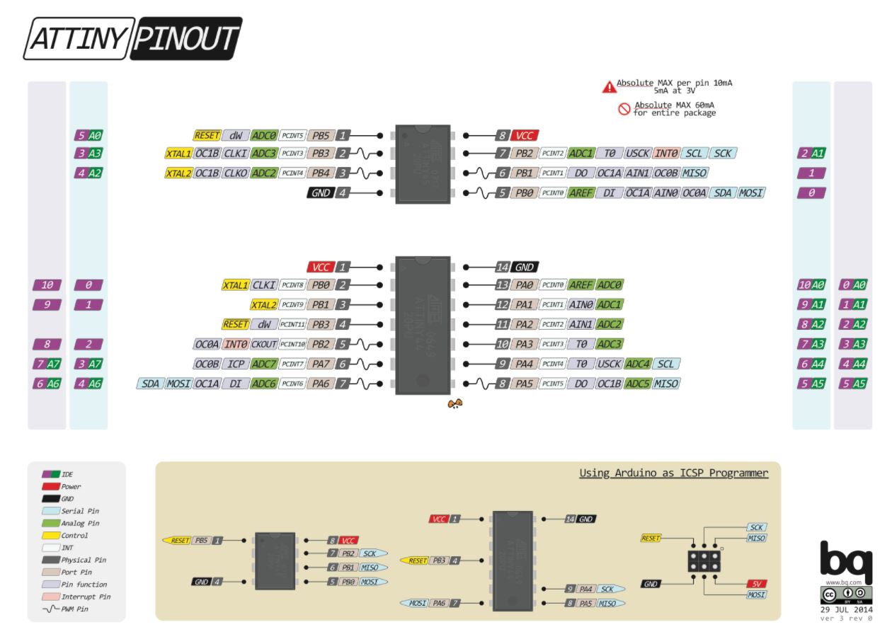
To see what does each pin I looked for the Attiny45 pinout diagram :
Using Eagle
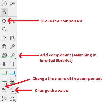
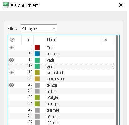
First thing is to import Sparkfun, Adafruit and Fab libraries (and click on use to effectively import them). The basic functions on Eagle I used :
| Schematic basic functions | Layers function in the board |
|---|---|
 |
 |
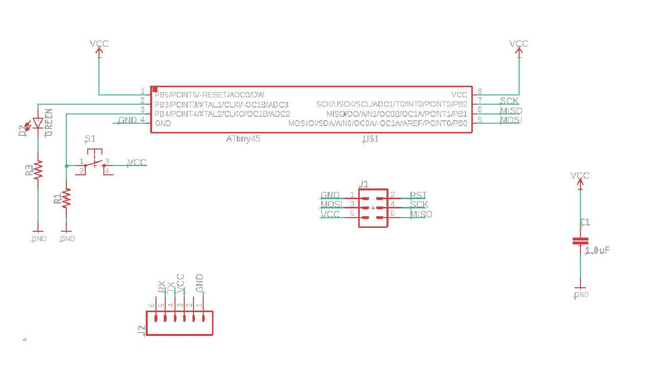
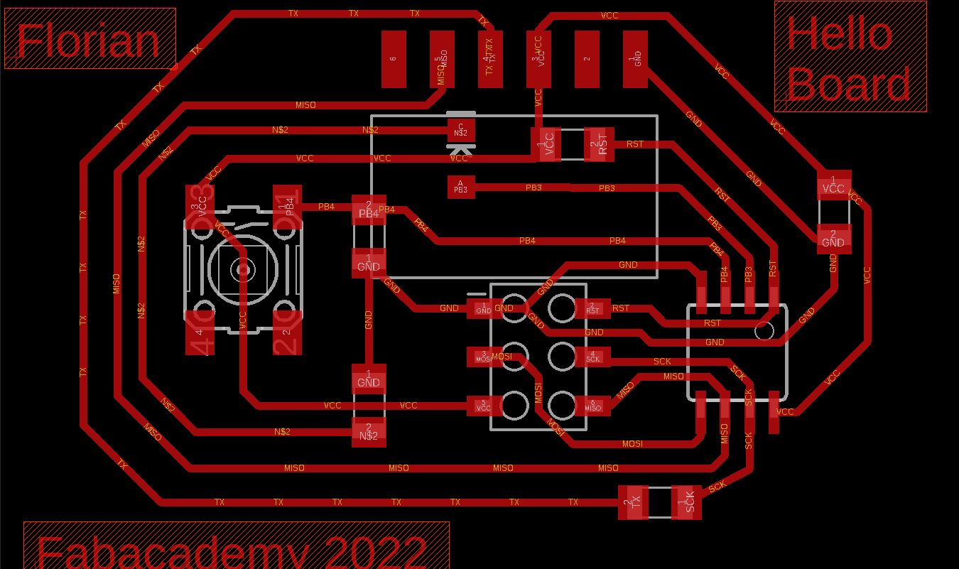
Drawing of the board :
| Schematic | Board |
|---|---|
 |
 |
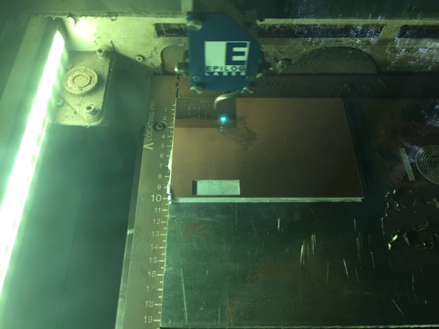
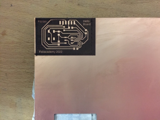
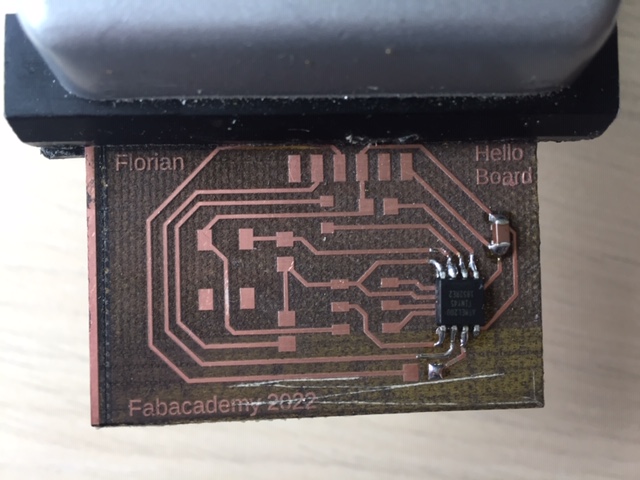
Laser cutting and soldering
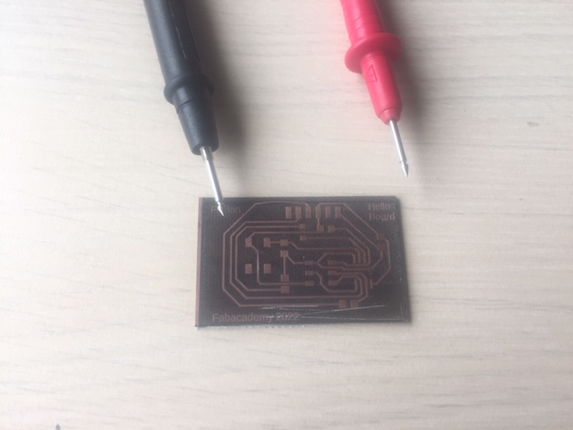
To laser cut the board I used the same settings as in the laser cutting week (10/100/1 for speed/power/frequency ratio) with 3passes. Then I checked the continuity :
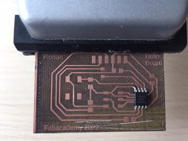
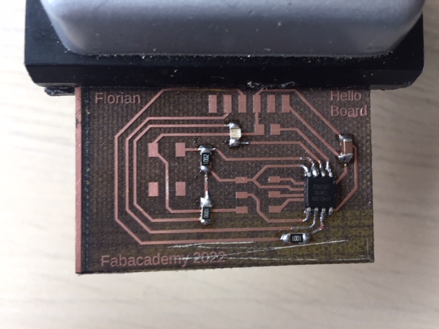
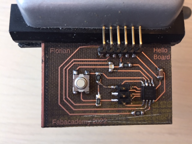
Soldering
Communicating with the board
I installed the softwares needed to program the Hello board with the FabTinyISP made in the Electronic production week
With the following screen showing that my softwares are installed,
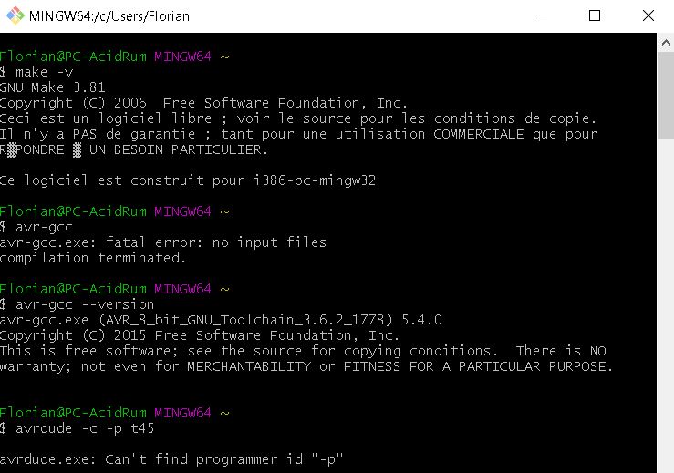
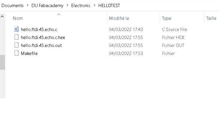
Converting code.c into code.hex
next step was to find a way to convert the echo.c code into .hex. After a few attempts with the make command, I finally made it work by copying the echo.make file into the makefile and the echo.c file into the hello.ftdi.45.echo.c file of my folder :
| echo.make | echo.c |
|---|---|
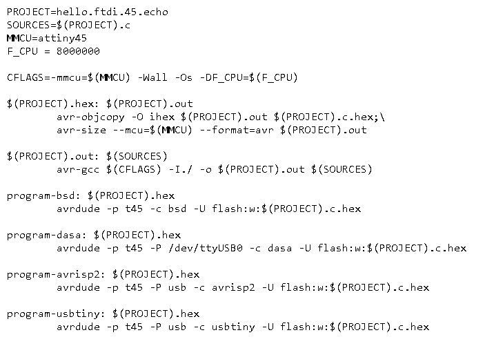 |
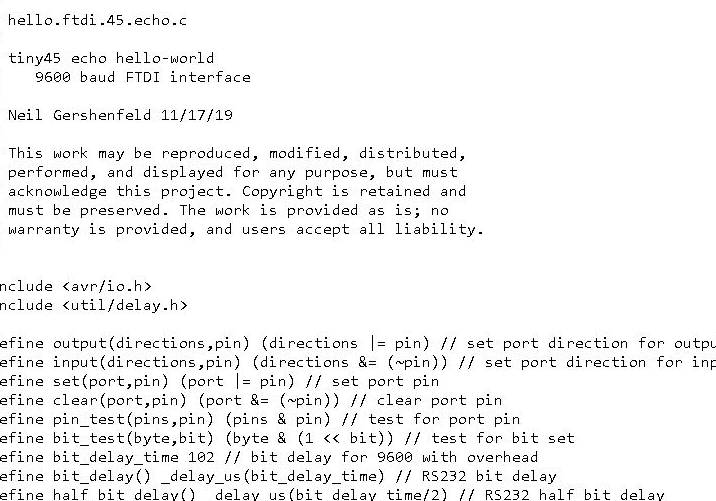 |
and then type the make command :
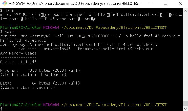
I had a few questions regarding this week and thanks to the explications of Jonah, I had a better understanding of what are the ins and outs of this week. The goal is to show the communication between the board and the computer via the Rx and Tx pins and the serial port of the computer.
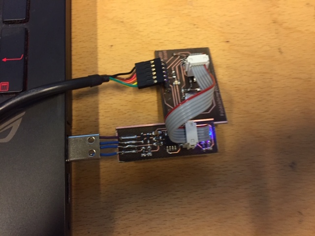
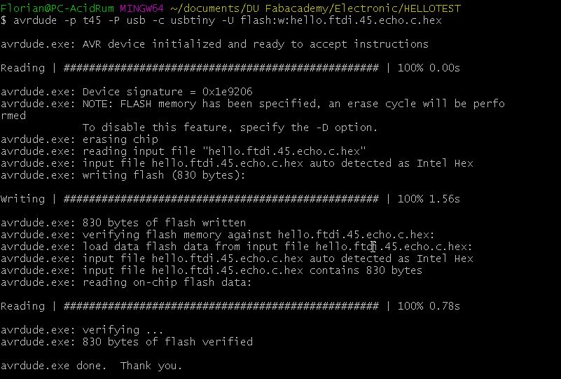
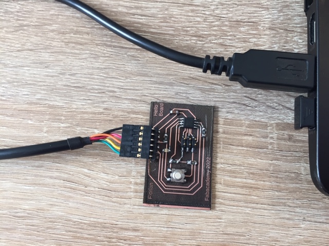
program the hello board
So next step is to connect the hello board to a source of power and to the programmer. And send the hello.hex code via the command avrdude -p t45 -P usb -c usbtiny -U flash:w:hello.ftdi.45.echo.c.hex :
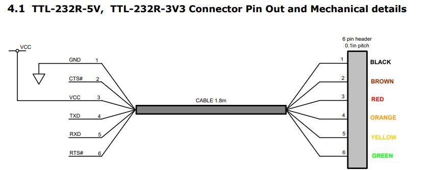
Communicate via serial port
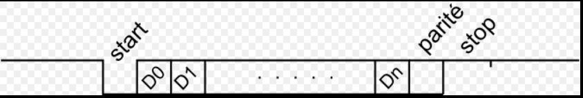
To communicate with the serial port, we need a UART cable because the signal coming from the microcontroller uses this UART protocol to communicate. According to wikipedia this is what the bits are used for in a signal where D0 to Dn are the data send :
I use arduino IDE to open the serial port and start typing “hello” :
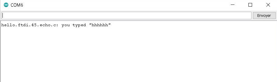
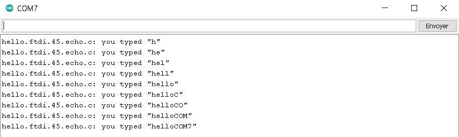
It seems that it takes only the first letter each time and stores the previous data send so let’s try one letter at a time :
Turn on a LED with a button
To code the correct pin, I looked into the pinout diagram of the attiny45 in arduino :
I used Arduino to write the code and convert it to .hex :
void setup() {
  // initialize digital pin LED_BUILTIN as an output.
  pinMode(A3, OUTPUT);
  pinMode(A2, INPUT);
  digitalWrite(A2, LOW);
}

// the loop function runs over and over again forever
void loop() {
  while(digitalRead(A2)==HIGH){
      digitalWrite(A3, HIGH);   // turn the LED on (HIGH is the voltage level)
  }
  digitalWrite(A3, LOW);
}
Here is the result :
group assignement
Oscilloscope
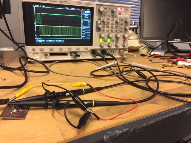
The oscilloscope will allow us to read the signal from a pin. I plug channel 1 and 2 to Rx And Tx and their respective ground to GND :
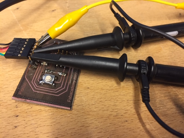
We calibrate the y axis (Voltage) to 2V/division and the x axis (frequency) to 2kHz/division.
Using the trigger
There is the possibility to use the trigger function to start recording when the voltage goes through a threshold. Click on the trigger button and select the good channel. Then use the trigger potentiometer to move it between the HIGH and LOW so it will trigger when the signal goes from HIGH to LOW on the start bit.
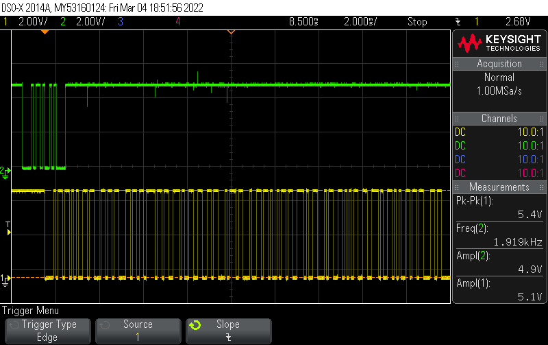
Here we can see the signal going through Rx and Tx :
logic analyser
I also read the signal with a logic analyser. I plug it to the GND, Vcc, Rx(orange) and Tx(yellow) :
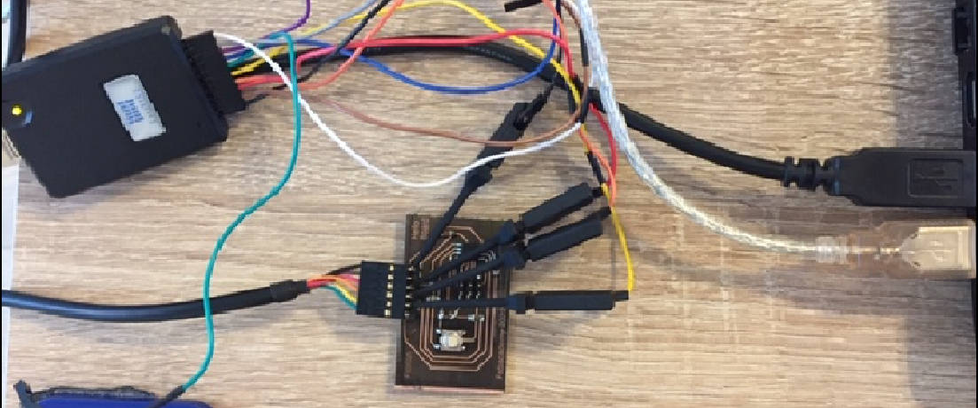
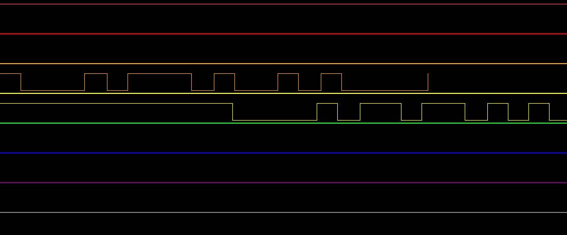
Result in video (During the recording I type “H” in the serial port):
The protocol analyser show this :
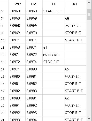
So we have the following data : 68, 65 and 6C which corresponds in hexadecimal to “h”, “e” and “l”.