9. Embedded programming
assignment
individual assignment:
read the data sheet for your microcontroller use your programmer to program your board to do something extra credit: try other programming languages and development environments
group assignment:
compare the performance and development workflows for other architectures
Research
Here is an Instructable on MIDI controller. It’s interesting for the Serial to MIDI converter software.
I found a Video about electronic drum coding. I took inspiration from the code he is using.
Choosing the good micro-controller
This week, I plan to design the midi-controller for my final project.
The minimal specs I need is a 4 analog pin :
I’ll look into the datasheet to see what data could be useful to me :
For the attiny45 :
-
8 total pins and 4 pins with 10-bit Analog to Digital Converter (ADC)
-
4K bytes program memory flash
-
256 bytes EEPROM memory. This is a reprogrammable memory which is non-volatile.
-
256 bytes SRAM memory which is volatile
-
Operating voltage 2.7 - 5.5 V
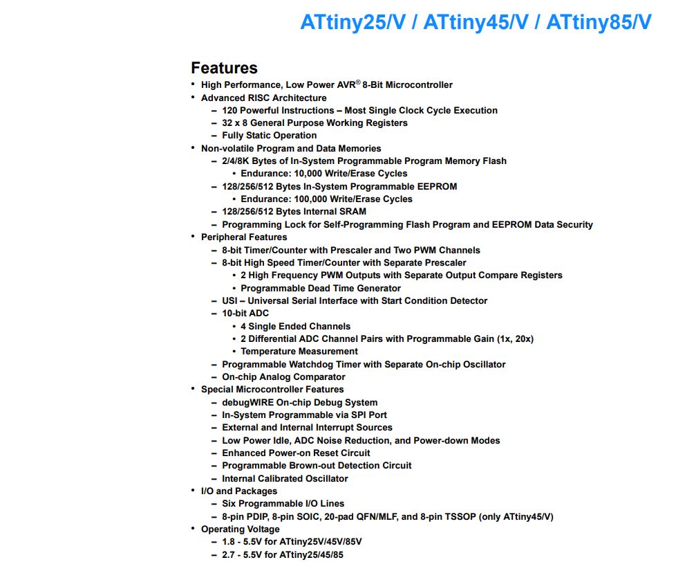
Looking at the specs above, 4 analog pins seems good enough for my project but 4K bytes program is too low for what I need to program. My midi controller hex file program is 11Ko.
For the Atmega 328P :
-
23 programmable in/outs pins
-
8 pins with 10-bit ADC
-
32K bytes flash program memory
-
1K bytes EEPROM
-
2K bytes SRAM
-
2.7 - 5.5V operating voltage
The Atmega 328P seems good for what I want. I have also extra program space if I want to plug a display.
For the SAM D11 :
-
22 programmable in/outs pins (depending on the version)
-
up to 10 pins with 10-bit ADC (depending on the version)
-
16K bytes flash program memory
-
4K bytes SRAM
-
1.6 - 3.6V operating voltage
Both the atmega 328p and SAM D11 seems good for what I want to do.
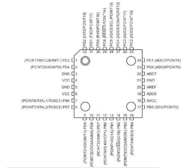
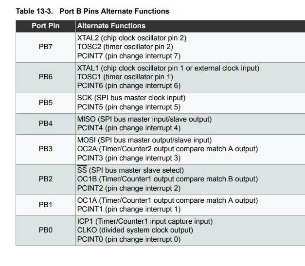
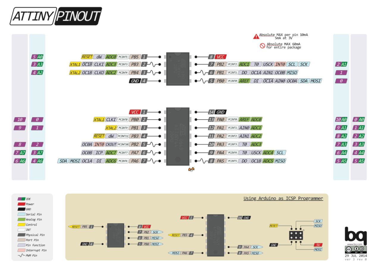
The pinout diagram is also shown in the datasheet as well as alternate functions for pins. An example here with the atmega 328P :
Programming Arduino
To start this week, I tried the MIDI controller program with an Arduino UNO. I looked into this Instructables first.
I installed the hairless MIDI serial bridge which will convert serial signal from the board to MIDI signal on the computer. To read the signal with a DAW software like Ableton, I need a “driver” like LoopBe1 (be sure that it’s unmute).
I first started with the simple following program :
#include <MIDI.h>

MIDI_CREATE_DEFAULT_INSTANCE();

static const unsigned ledPin = 13;      // LED pin on Arduino Uno

void setup(){
    pinMode(ledPin, OUTPUT);
    MIDI.begin();
}

void loop() {
  digitalWrite(ledPin, HIGH);
  MIDI.sendNoteOn(30, 127, 1);    // Send a Note (pitch 30, velo 127 on channel 1)
  delay(1000);                // Wait for a second
  MIDI.sendNoteOff(30, 0, 1);     // Stop the note
  digitalWrite(ledPin, LOW);
  delay(1000);
}
Every 2 seconds, it will send the note 30 for 1 sec with 127 velocity and turn on the LED.
debugging MIDI signal
for the First test I had the following error message :
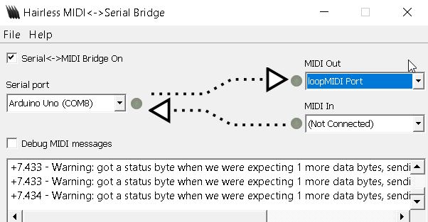
After changing the baudrate in the serialMIDI.h file to 115200 bps (the same baudrate as in the hairless MIDI) it worked well. Also the LoopBe1 driver has to be unmuted.
Result :
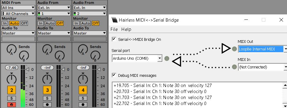
We have the correct MIDI message in the hairless MIDI software.
Next step, I programmed the Arduino with a code to receive the signal from my drum pad and send the MIDI to the serial port. I took the code from this video modifying it for my application :
#include <MIDI.h>

#define LED 13
#define PADS 3
#define CHANNEL 1
#define DEBOUNCE 60

// Create and bind the MIDI interface to the default hardware Serial port
MIDI_CREATE_DEFAULT_INSTANCE();

int sensitivity = 100;
int threshold = 10;

unsigned long timer[PADS];
bool playing[PADS];
int HighScore[PADS];
byte note[PADS] = {1, 30, 60};

void setup() {
  // put your setup code here, to run once:
  Serial.begin(115200);
  MIDI.begin(MIDI_CHANNEL_OFF);
  for (int x = 0; x < PADS; x++){
    playing[x] = false;
    HighScore[x] = 0;
    timer[x] = 0;
  }
}

void loop() {
  // put your main code here, to run repeatedly:
  for (int x = 0; x < PADS; x++){
    int volume = analogRead(x);
    if (playing[x] == false && volume >= threshold) {
      if (millis() - timer[x] >= DEBOUNCE) { //millis() returns the nbr of millisec passed since arduino began running
        playing[x] = true;
        playNote(x, volume);
      }
    }
    else if (volume >= threshold && playing[x] == true) {
      playNote(x, volume);
    }
    else if(volume < threshold && playing[x] == true) {
      MIDI.sendNoteOn(note[x], HighScore[x], CHANNEL);
      MIDI.sendNoteOff(note[x], 0, CHANNEL);
      HighScore[x] = 0;
      playing[x] = false;
      timer[x] = millis();
    }
  }
}

void playNote (int pad, int volume) {
  float velocity = ((volume) / float(sensitivity - threshold))* 127;
  if (velocity > 127) velocity = 127;
  if (velocity > HighScore[pad]) HighScore[pad] = velocity;
}
The function playNote() allows to store into HighScore[] the highest Volume. And it defines Velocity which takes into account sensitivity which is an adjustable variable set in the beginning.
The result in video :
You can also check in the input devices week a test of a similar code with a board I made in week 11.
Sensor used
I used a piezo electric sensor which converts the change of pressure to an electrical charge. I document it more in the input devices week.
Programming my own board
I documented on the Electronic design week how I programmed my board with a code to turn on a led with a switch.
To code the correct pin, I looked into the pinout diagram of the attiny45 in arduino :
I used Arduino to write the code and convert it to .hex :
void setup() {
  // initialize digital pin LED_BUILTIN as an output.
  pinMode(A3, OUTPUT);
  pinMode(A2, INPUT);
  digitalWrite(A2, LOW);
}

// the loop function runs over and over again forever
void loop() {
  while(digitalRead(A2)==HIGH){
      digitalWrite(A3, HIGH);   // turn the LED on (HIGH is the voltage level)
  }
  digitalWrite(A3, LOW);
}
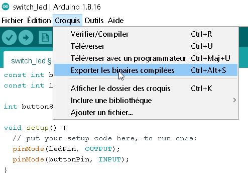
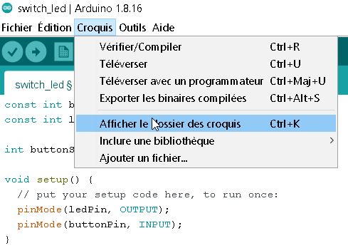
converting to .hex
To convert to .hex with Arduino IDE, click on “export compiled binary” and then “show sketch folder” :
Then I connected the board to the programmer and to a source of power and send the code via the command (make sure you are in the good folder) :
avrdude -p t45 -P usb -c usbtiny -U flash:w:switch_led.ino.hex
Here is the result :
group assignment
Arduino selection in the fablab :
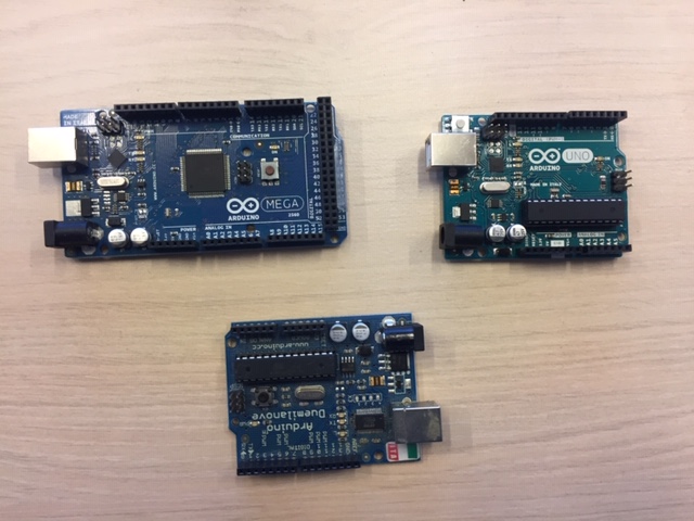
This week, I did the group assignment with Caroline who went from Bordeaux to Paris.
First question : what kind of workflow can we compare ?
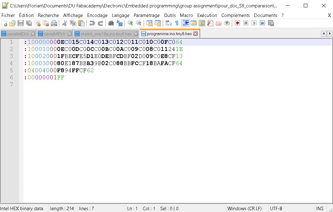
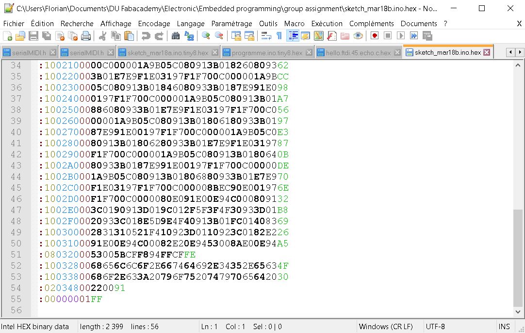
- Programming language : Does the size change if we convert from .C to .hex or from .ino to .hex ?
Converting the files using the Arduino IDE :
| From .C to .hex | From .ino to .hex |
|---|---|
 |
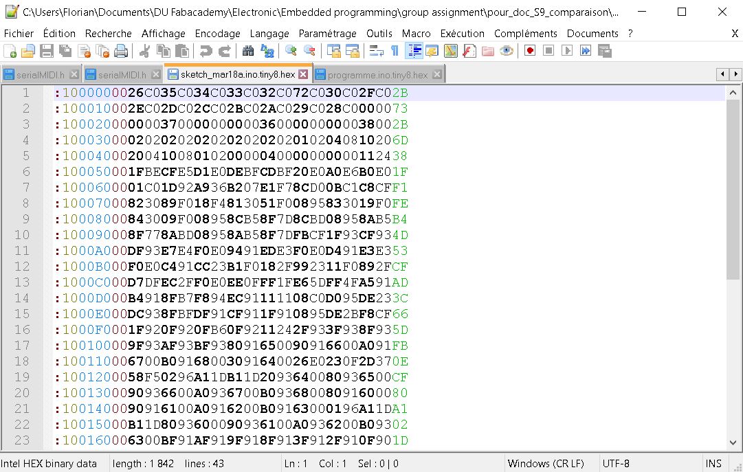 |
The .C file is much smaller than the .ino.
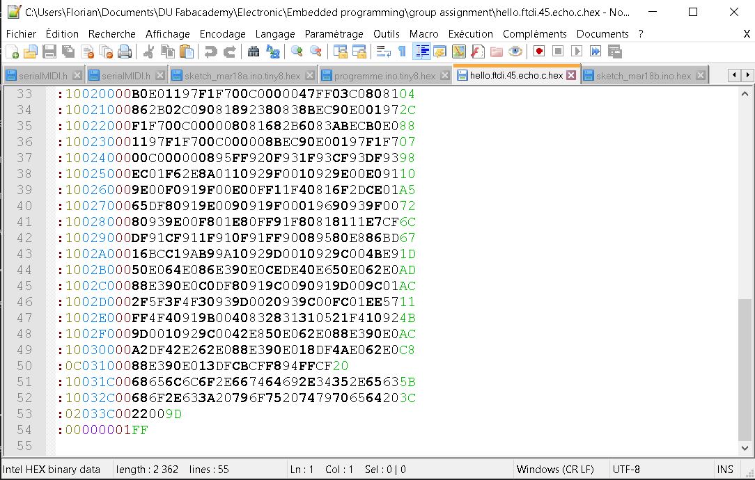
- Does the software we use to convert to .hex has an impact in the size of the file ?
| Using AVRdude | Using Arduino IDE |
|---|---|
 |
 |
The file is the same size using AVRdude and Arduino IDE (only 1 line difference). Looking in the compiler, it seems that Arduino IDE uses AVRdude to convert.
- Can we see a difference via the logicAnalyser if we transfer the program which came from .ino or from .C ?
Second question : How to compare performance ?
- Difference between micro-controllers : Do we see a difference in time response between two microcontroller for a same program ?
We made a test with my program which converts the analogical signal coming from a piezo sensor to a MIDI signal. Comparing the program time-response between two micro-controllers (Arduino Uno with Atmega 328P and Arduino MEGA with Atmega 2560):
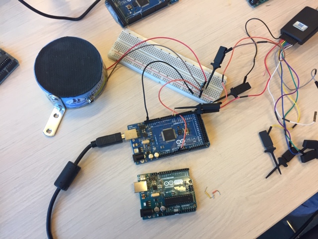
With the Atmega 328P :
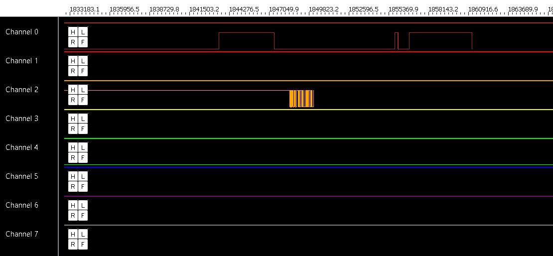
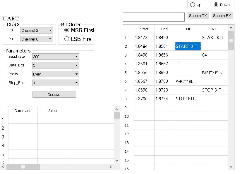
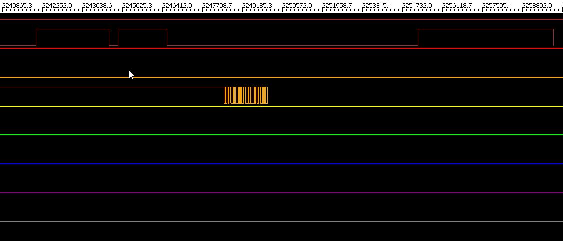
| Channel 0 : Analogical pin; Channel 2 : Tx pin | Protocol Analyser |
|---|---|
 |
 |
With the Atmega 2560 :
| Channel 0 : Analogical pin; Channel 2 : Tx pin | Protocol Analyser |
|---|---|
 |
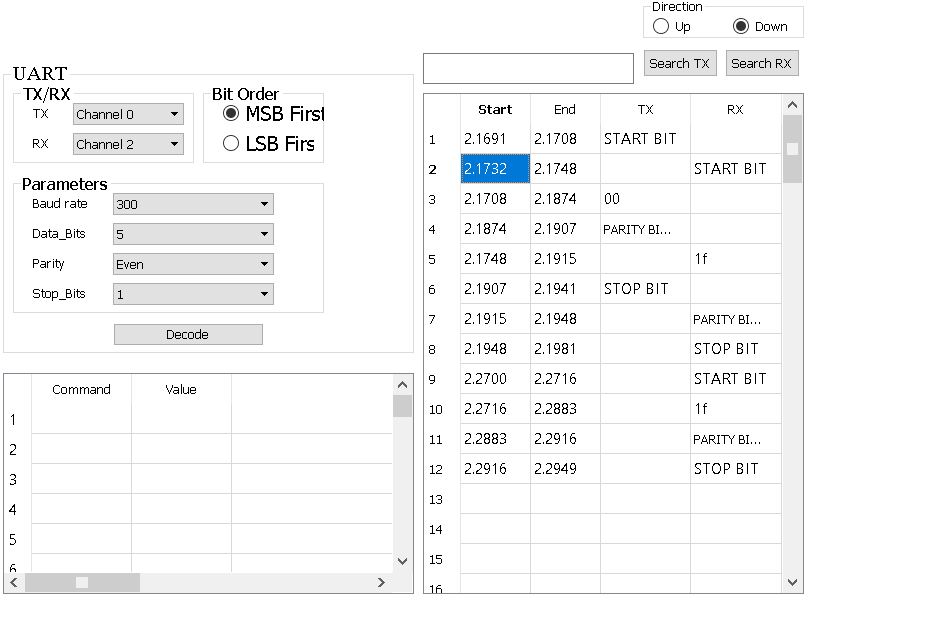 |
Looking on the protocol analyser, there is a 0.0011 sec difference between input/output with Atmega 328P and a 0.0041 sec difference with Atmega 2560. The mega 2560 is almost 4 times slower than the mega 328p.
Understanding the analogical signal
Looking at the channel 0 of the logic analyser, there are several “bump” for only one strike. I wanted to check on the oscilloscope if those bumps can be seen too :
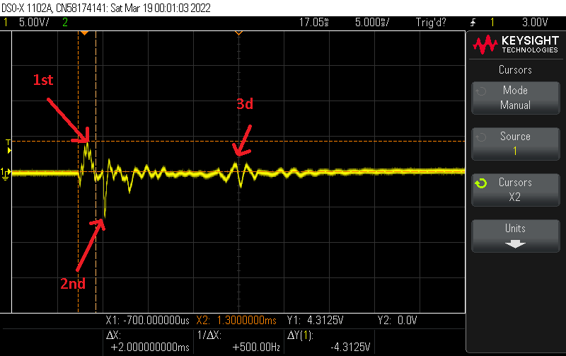
So we can see a few bumps. It explains why I have to put a timer, a highscore and a threshold in the program if we only want to hear one sound per strike.