Embedded Programming
This week's group assignment was to compare the performance and other characteristics of different boards. The individual assignment was to program your board from week 6 to do something!
Group Project
For the group project this week, we were split into groups based on our knowledge of programming. I don't have a whole lot of experience with programming. I've done a bit for previous assignments and Intro to Digi Fab, which I took before this, but I have no formal knowledge, so I was put in the beginners group. We started by learning the basics of Arduino using Tinkercad's circuit function. After getting a better grasp of what we were doing, we went to categorize and compare a few of the different boards we have in the lab. We specifically looked at the Feather M0 lora 900MHz, ADA Fruit Mini Microcontroller, and the RedBoard. We looked at aspects like the processor family, clock speed (which is operating speed of the microprocessor), and memory.
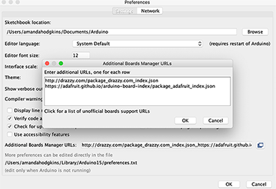
After that, we went ahead and programmed the Feather M0 with a blink command. To do this, we followed this tutorial on the ADAfruit website. To start, we opened preferences in arduino and added the board manager url from ADAfruit.
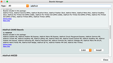
After that, we installed the correct board package which contained the specific board we were using. In this case, the SAMD boards was the one we wanted.
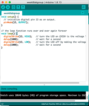
We then plugged in our Feather m0 and selected the correct port and board within the tools selection in Arduino. We then copied the blink code from the tutorial website and uploaded it to the Feather m0!
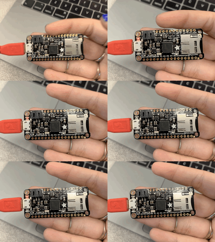
It worked without a hitch! See it in action!
Individual Project
My idea for programming my board to do something was to code my board to flash at different intervals/frequencies depending on how many times the button gets pressed. Basically, I was thinking that if you press the button one time, the led will flash 3 times at a slow interval. If you press the button twice, the button will flash as a quicker interval 4 times, and if you press the button 3 times, it will flash even faster 6 times. My basic knowledge meant that I knew how to code a blink function, so I figured it would only be a little bit different than that to get it to do it at different speeds. In order to edit my code and test it easily, I used Tinkercad, where I created a circuit with a button and led just like my board. I found this forum where someone was working on a similar function to what I was trying to do, and I used their code for the button as a guide to setting mine up. After I had gotten to a point where I felt it could work, I tested it and it didn't. I went to Professor Goodman's office hours for help with troubleshooting my code and editing it to what I wanted. He was extremely helpful in helping me fix my issues! We found that my circuit was set up slightly different than what my actual board would be, so we fixed that to make it easier to transition my code. I had a couple of other small errors in my code, and after fixing those, my code worked! You can see it below!const int button = 3;After that, Professor Goodman advised me to make a copy of the circuit I was working on in Tinkercad, so as I worked on achieving the result I wanted, I had something to fall back on in case it got messed up. I then started editing the copy towards the differing button press idea. With what I had, the different outputs would happen depending on the sequence of pressing the buttons, so it would always start with the first blinking speed, before going to the second when the button was pressed a second time. This wasn't what I wanted, and after working with Professor Goodman, I decided to add an integer for the last button state, so when the button was read, it would take both the current state and the previous state into account. This caused the differentiation between counts that we needed to read and separate presses. After that, I edited each of the blink functions to what I wanted, and ran the simulation in Tinkercad. It worked! My code was all set to be transferred to my board. I then went into Arduino and selected the proper board and port, just like electronics production week!
const int led = 2;
int buttonState = 0;// keep these the same when putting in arduino
int buttoncount = 0;
int lastbuttonState = 0;
void setup() {
pinMode(button, INPUT_PULLUP);
pinMode(led, OUTPUT); }
void loop() {
for (int b= 0; b<100; b++){
buttonState = digitalRead(button);
if (buttonState == HIGH && lastbuttonState==LOW) {
buttoncount ++;}
lastbuttonState = buttonState;
delay(20); }
if (buttoncount == 1) {
for (int i=0; i< 3; i++ ) {
digitalWrite(led, HIGH);
delay(400);
digitalWrite(led, LOW);
delay(400);
buttoncount = 0;}
}
if (buttoncount == 2) {
for (int i=0; i< 4; i++){
digitalWrite(led, HIGH);
delay(250);
digitalWrite(led, LOW);
delay(250);
buttoncount = 0;} }
if (buttoncount > 2) { for (int i=0; i< 6; i++){
digitalWrite(led, HIGH);
delay(100);
digitalWrite(led, LOW);
delay(100);
buttoncount = 0;} }
else { digitalWrite(led, LOW); } }

I made a new file and pasted my code from Tinkercad. Before I could upload it, I had to edit the numbers for the integers of my button and led since the pins are different in the attiny1616. I used the diagram below to convert them over, and inputted the correct pin numbers. If you look in my code above, you can see that I define the led and button pins as 2 and 3. This is because that was where I placed the wires that connected to those components in my Tinkercad Arduino model. These integer numbers are different in my actual code. I used the diagrams of my board from Electronics Production week to see there the connections of my components fit with the attiny itself. In my case, when looking at the following diagram this was pin 6 on the attiny for the led and pin 15 for the button. I then used the conversion map for analog/digital pins (the orange and blue squares or the 2nd row from the inside) to find the corresponding values I needed for my actual code. To do this, you take the place of the actual connection, and then look at the pin number in whatever category you need. In my case, this pointed towards pin 13 for the button, and pin 4 for the led. I then substituted those numbers in my integers of my code!
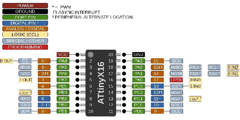
Once that was done, I verified my code and uploaded it.

It was a success! Here you can see what happens when you press the button once!
And twice!
And three times!