Electronics Design
Our group assignment for this week was to observe a microcontroller and test it using the equipment in our lab, and the individual assignment was to create and program a board.
Group Assignment
To do this week's group assignment, we used a multimeter and an oscilliscope to test a board made by one of our instructors, Professor Goodman. We started with the multimeter, where we tested the voltage. As you can see, the board has an input voltage of 5 volts.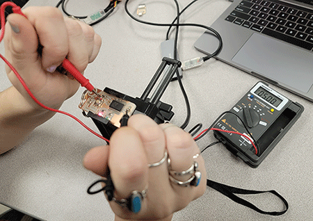
We then checked the voltage when the LED was flashing, which turned out to fluctuate. When the LED was on, the multimeter read 5 volts, and when it was off, it read somewhere around 0.
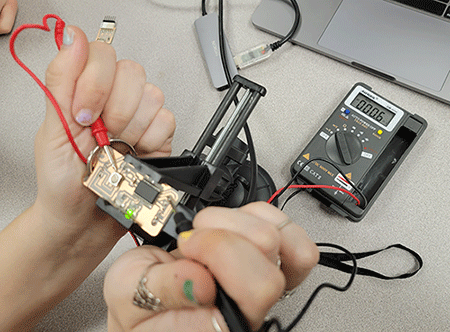
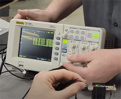
Because the voltage changes so quickly when the LED flashes, the multimeter can't pick it up super well. This is where the oscilliscope came in! This machine is much more precise, so it can actually collect this changing voltage, which you can see in the fluxuation of the lines.
Individual Assignment
Creating the Board
For my portion of this week's assignment, I started by downloading the software KiCad, which was what we used to create our circuit boards. I also downloaded and installed the fab academy library for KiCad through GitHub. I went to create my board, and realized that I was still missing some components that I needed, before realizing I didn't have the main library installed. Because I have a Mac, adding this was a bit of a pain, and I ended up having to go into terminal to get things to work properly. Anyway, I eventually got everything that I needed, and was all set to go! I started by adding the basic parts that made up the echo hello-world board from Neil, before adding a button and a LED to modify it.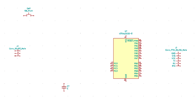
Next, I went and added the connection wires to the diagram, adding the resistors in the proper order.
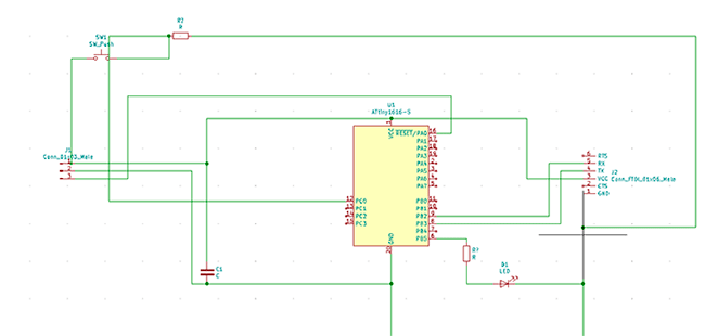
My modifications and connections were finished, so I could move on to the PCB! I switched to the PCB window and opened the schematic diagram. The green connection lines from the previous window were gone, and were replaced with white lines from one component to the other that it connected to. These weren't the nicest, and after a long while of playing around with the orientation of them, I got to a point where thre weren't many crossing lines. I then clicked on the red wire tool and created paths between the elements. After double checking with Professor Goodman, he noticed that the input and output connection of the button was on the same side, which was wrong.
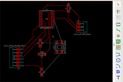
Professor Goodman looked over my schematic diagram and PCB, before finding the cause of my problem! When I was connecting the elements in my schematic diagram, I hadn't actually connected the button to the connector, as you can see in the picture below.
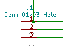
This was a quick fix, and then I was back to a slightly altered PCB board. I fixed up the new wire connections, and my PCB was one step closer towards being done! I set my traces within Kicad in the settings of the PCB editing page. These were .25 mm thick which would work with the bit I was using.
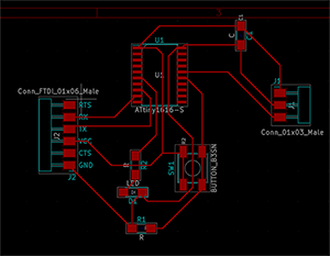
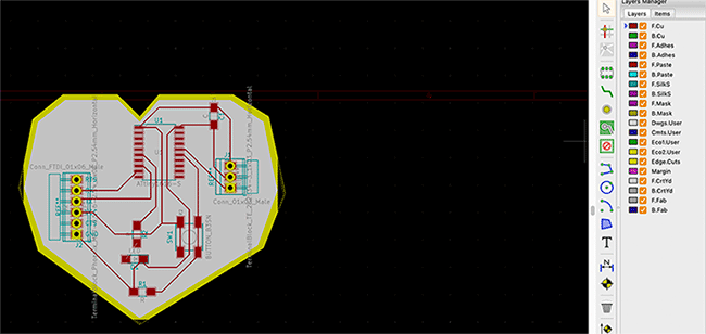
I added what would make up the holes for my pins, which you can see as the yellow circles above the connector components of my board. The final step in creating my PCB was to add a background and border. I clicked on the dwgs.user layer and then used the polygon to create the heart shape that I wanted my board to be. To use mods with this file, I also had to add a border, so I did the same thing on the edge.cuts layer, which added the yellow you see in the screenshot below.
I then exported these files and opened them in Illustrator, where I edited the layers before opening them in mods. In mods, I opened a server program for our specific mill, in this case the Roland SRM 20, and opened the file. I started with traces, inverting the image and altering the settings correctly.
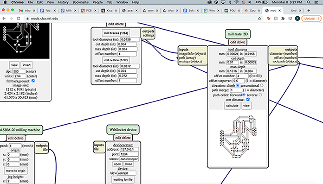
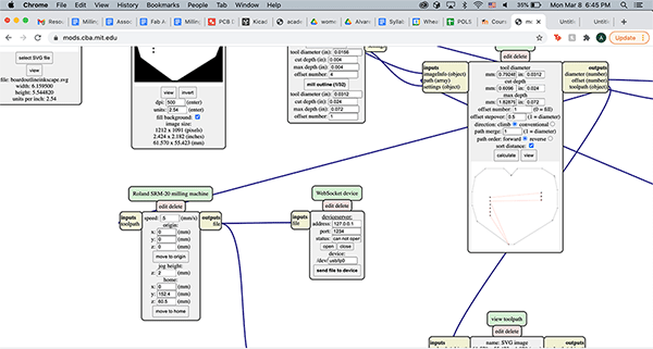
I did the same thing with the file for the holes of my board and the outline, saving everything on a USB.
Milling
I started this step by first preparing the actual mill. I switched the bit to a ball nose for the traces, put my material on the bed using double stick tape, and set the origin/z. Next, I opened my file and went to do an air cut as a test, and to my horror the exact opposite of that happened. The bit actually plunged into the bed. It was terrifying but luckily my bit didn't break (whick was great because I had literally just broke that exact same bit by dropping it on the floor 3 minutes before this happened). You can see the hole I created below. Terrifying!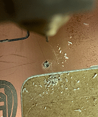
After that ordeal, I went over everything again, this time having a successful air cut. I was all set to actually mill my traces!
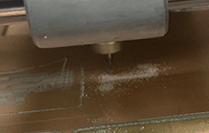
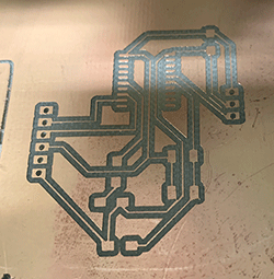
Here they are!
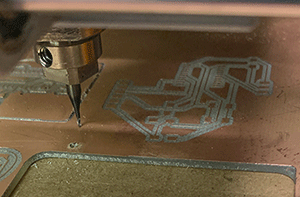
I switched the bit after that and milled the holes next.
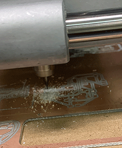
This is what I had after that!
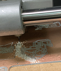
The final step was to cut the outline of my board!
Success!
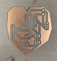
Now I could solder!
Soldering
When adding the proper components to my board, I started by using solder paste to attach the button and LED.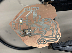
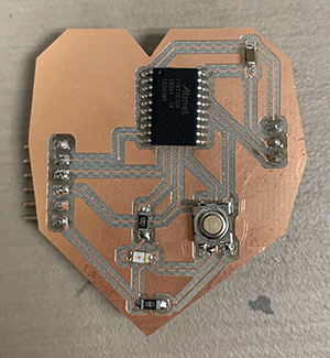
Everything except the connectors was added with solder paste. I used liquid solder on the pins. After adding all the components, I checked the connection of most of them using a micrometer. It seemed to hold up, and I was all set to program. Here's everything connected to my board!
Programming
I started by downloading Arduino and the correct core for my microcontroller. I installed this core in Arduino, before plugging in my board to a USB to FDTI cable so I could actually program it. I looked under the ports section of the tools panel in the nav bar and chose the correct one for my megaTinyCore. When I went to do this the first time, the correct port didn't show up. I noticed that my board was SUPER hot and realized that something was wrong. After using the micrometer to test, when I pressed the wire things to the first and 20th steps of the 1616, it went off so something was wrong. I went to solder it off and noticed that the solder on my button had also attached to the path that went in the middle of it, so I took off the button as well. The trace for my button was actually very close to the other path, so I used an xacto knife to scrape off some of the copper between them to help create a gap. I reattached this and the 1616, and my board was fixed! I plugged it back in to the computer, and it actually showed up in the port section!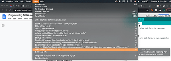
I then copied the hello echo program from Neil and uploaded it to the sketch window, before uploading it to my board.
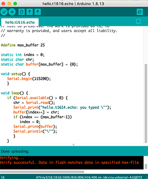
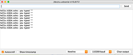
This uploaded with no issues, and when I typed something in the serial monitor, it worked!
I then added code that would cause the LED to light up when I pressed the button.
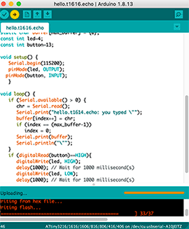
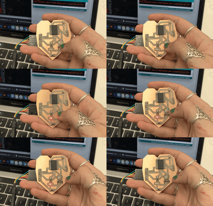
Again, this worked really well, and you can see it in action! Yay!
