Final Project!
I don't really have a finalized idea for my project yet. If you want to see my ideas so far, go to my Principles and Practices page!
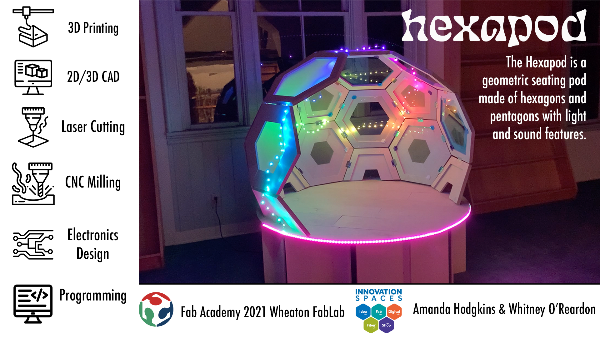
UPDATE! As of March 11, I now have a functioning idea! I am now collaborating with Whitney to make a seating pod/area for our lab/campus! We were originally thinking of collaborating to create a pavilion, but after assessing our budget and time frame, decided that was a bit too much, so we scaled down. We found a couple of interesting ideas on google while browsing for inspiration, before finding a design that we really liked!
This came from the website of an industrial designer. Whitney and I really liked the hexagon shapes, as that's part of the logo of the fab lab here at Wheaton, and felt that its look overall was very compelling. In order to change the design up a bit, we wanted to do something different with the faces of the hexagons themselves in addition to adding other elements. After a few initial sketches which I'll add below, we came up with the design of different sized hexagon borders that got smaller as they went up. This is the third design shown below!
We also made a paper model of our seating pod to better understand how everything would go together!
During this process, we realized that the dome is not just made of hexagons, but also pentagons. This causes the curving shape to form! After figuring this out, we added pentagons to our paper design, and it fit together much better. After calculating how large the pod would be using our wood, we decided we wanted to make it taller, so we added a row of hexagons to the bottom. Whitney created a mockup of our whole geometric orb in Fusion. After our design was finalized, we went in Fusion and created files to use with the CNC to cut out all of our pieces. We decided on having different sized holes, where the shapes would be more open on the top. We would have 2 layers of each shape for added durability. The general size was 2 inches thick, and the other section's size depended on where it wen in the design, ranging from 2 inches thick to 8 inches thick. In order to cut these shapes out on our pieces of wood, we made the hexagons and pentagons into halves, and then nested them within our stock. You can see the different sizes of our hexagon halves in the image below! The task of creating these files for the hexagons and pentagons was split between Whitney and I
We cut everything out with the Axiom and assembled it, which you can see on my Make Something Big Week page in more detail. As we got to the end of this process, we realized that just adding the hexagons to the bottom row wouldn't actually work due to the angles of construction, so we stopped at the row above that. They ended up fitting in the paper model due to the fact that that geometry isn't strict and we could manipulate the paper in ways that didn't actually work for our structure. We just didn't end up using these extra hexagons and this is what we had at the end of make something big week!
As Whitney and I were working on planning more of our final project, we decided that we wanted to add a base to our struxture for added height. We also decided to add acrylic panels to the hexagons and pentagons so it would be a bit more enclosed. For electronics, since this was a group project, we needed two separate systems. I decided on focusing on neopixels for both the base and the top part of the structure. The original plan was to have a button that would change color/pattern modes for the bottom lights and then the top lights would turn on when someone got in the orb from a pressure sensor that was in the base. Whitney's electronics portion was going to be sound based. Her original idea was to load songs via an sd card and use a remote and sunsequent sensor to play them. With our idea of adding a base to the structure, we also decided on making the bottom of our orb flush. To do this, we needed to create pentagon shapes without a point, since that was what would fill the open space left from make something big week. I did this in Fusion.
Whitney worked on designing the base, which would be made up of interlocking pieces and a floorboard-esque circle on the top, which we would set the rest of our structure on. Our lab ended up being moved across campus due to construction on buildings, and then it was moved again due to fire safety issues. Because of this, our Axiom was out of commission for a while, so we went to the Dassault lab to cut out what we needed.
Whitney and I familiarized ourselves with the ShopBot at Dassault and cut a few of our boards there, but our Axiom at Wheaton ended up getting fixed, and we worked on the rest there.
We assembled the base and then decided to wait on putting the top boards together until we got the electronics done and figured out where we would put them.
Electronics
For my electronics portion of this project, I dealt with lights. My initial plan when making my board was to have 2 neopixel strips (one for the top and one for the bottom), a button to turn on and off the bottom lights, a button to change modes for the bottom lights, a button to change modes for the top lights, and space for a pressure sensor which would turn on the top lights. You can see both my schematic and my pcb below!
I milled my board and it turned out okay, but not great. Some of the traces were pretty thin, and it didn't actually mill out a few spots you can see in the photo below.
I used an xacto knife to scrape these traces clear and I went ahead and soldered all of my components onto the board, and it ended up looking like this!
I hadn't really had any major issues so far, but ran into one when I went to program my board. When I went to plug in one of my neopixels into the board, I realized that it wasn't actually connected to ground or vcc. After looking at my diagrams, I realized that when I made my schematic, I indicated for certain components to be connected to vcc and ground, but never actually indicated which parts of my attiny were ground and vcc. This caused those components to be connected to one another, but not the actual path I wanted them to be a part of. To fix this, I ended up adding two wires to my board.
Once I had done this, I was all set to go and my board could actually be programmed! I started by getting the code for the pressure sensor to work! For this I started with the piezo buzzer sensor code that I used in Machine Week and edited it to work with the lights! Once that was all set, I sterted in on trying to get the light modes to work. I found this tutorial which worked really well for switching between colors and pattern modes with a button, but it had a few issues that didn't exactly match my vision for what Iwanted my lights to do. Firstly, the mode could only be switched after whatever pattern was going was fully completed. I wanted to be able to switch modes without this sort of hindrance. Another point with this code that I didn't like was that the light modes only went for a certain time. I wanted to have them go continuously. That code was a good start, but I wanted to look for something better! After a bit more searching, I found another tutorial that was about doing multiple light effects with an arduino. I altered this code to match what I wanted for my own lights and found a few more points. In this code, the effects were continuous, which I liked, but they only changed to one other effect. On top of that, the effect only changed when the button was held. If I substituted a regular button for a switch, this wasn't much of an issue, but I still wanted more light effect options. Both of these tutorials had different aspects that I liked, and I tried to combine them to get my desired result but with little success as I kept running into problems when I tried to get them to work together. I fought with it for a couple of days, before going to Professor Goodman for assistance. He was an absolute godsend and ended up figuring out how to combine the cases from the first tutorial with the continuous light modes from the second. You can see it working here!
Once I got it working for one set of lights, I created a second instance of the code and changed it to match my second set of lights and second button. Now all of my buttons and light modes worked! I started to try and integrate the pressure sensor into my code, but after running into more problems and discussing it with Professor Goodman, we decided that it would be best to stick with what I have. In the end, I ended up having two sets of lights with a button for each that changed the light modes/patterns/colors of its respective strand. Whitney's initial plan of using a remote and sd card reader also ran into issues, and she ended up with speakers and an IR sensor that would play randomly generated music when someone got in the orb.
Final Stretch
Once both Whitney and I's electronics were done, we went ahead with the rest of the assembly. We ended up deciding to use wood glue to secure the floorboards of the base except for two on the edge that we would slide out to put in the electronics. I created laser cut files of hexagons and pentagons for the acrylic panels that would go in the dome, and Whitney and I cut them out using the laser cutter. To attach these to our structure, Whitney created sort of hook shapes that would go in the corners of our wooden shapes and would hole up the acrylic pieces. These were 3D printed and you can see an example of what they would look like below.
I created a control panel in Fusion that would house the buttons for the lights and the IR sensor that Whitney was using for her sound system.
I 3D printed this, and my buttons fit perfectly, but the hole for Whitney's IR sensor was slightly too big. This panel would be attached to the bottom of our dome structure, and the wires that connected these elements would go through a crack in the floorboards to the spot that our boards would be housed. After all of our electronics parts were ready, we started to put them together in the structure itself. Whitney added holders for the speakers in the base and long wires that attached to her board. When I went to attach both of my lights to my board, one of the connection wires that I soldered came apart, so I had to solder it back on. I went ahead and did that, and then attached wires between my buttons and my board. I had issues getting these to stay connected, and in my fiddling around, ended up wiping off one of the traces on my board, so I had to head back to the lab and add a solder jumper in the gap.
After fixing this problem, I went ahead to add my buttons again, and they worked! Whitney and I then worked on adding all of our electronics to the control panel and putting my lights on the structure.
We slid the floorboard panels back into place and set up the lights for the top and the base of our seating pod! It was done!