Electronics Production
This week's assignment was another one with both group and individual projects. Our group project was to characterize and explain the machine we use to make PCBs. The individual part was to make our own programmer/PCB.
Roland SRM-20
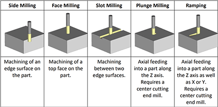
The machine we use in our Fab Lab is the Roland SRM-20. This is a desktop mill that has a diverse range of capabilities. It can cut materials such as modeling wax, chemical wood, foam, acrylic, poly acetate, abs, and pc board. The bits used in this machine range from .016" to .25", and come in many different types. There are flat end mills, square end mills, ball end mills, and more. These bits can be made of high speed steel, cobalt, or solid carbide and usually have coatings of titanium nitride, titanium carbonitride, and aluminum titanium nitride. Flutes are spiral-shaped cutting edges on the sides of end mills to allow materials to escape when the mill is in a slot or pocket. Usually, end mills have 2, 3 or 4 flutes, but it depends. Our mill has a workpiece table size of 9.14 x 6.17", and a maximum distance from the collett tip to table of 5.15". A few softwares that can be used with the Roland mill are Vpanel, Mods, and Flatcam. Vpanel allows users to interact directly with Roland SRM-20 Desktop mill and upload their job to the mill itself. Users can make real time edits and control the Roland, which can be really handy from time to time. Vpanel also allows different type of files other than “.rml”. Mods is a website created by Neil. It’s a multitool software that includes CAM software for multiple devices that can be used for a wide range of machines. It is an open source, fully editable software that gives users the ability to create many things for many machines or softwares. Flatcam is an open source PCB CAM tool. The compatible file types for Flatcam are gerber files, svg files, g-code, and excellon files. If you don’t have a premade design, you can create one from scratch that will be exported for use in a milling machine.Some milling definitions and diagrams
- Feed rate: the speed at which the cutter advances on the workpiece
- Usually expressed in inches or millimeters per revolution
- Expressed in revolutions per minute
- Expressed in mm
- usually given in the third perpendicular direction (Z-Direction)
Spindle speed: the rotational frequency of the spindle of the machine
Plunge rate: the speed at which the router bit is driven down into the material when starting a cut
Depth of cut: provides necessary depth of material that is required to remove by machining
Group Project
To start our group project for this week, we used a trace file from the assignment page of the schedule and opened it in mods. We edited the settings for the Roland mill and saved the file.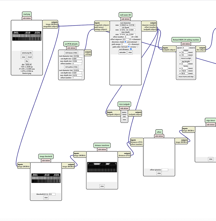
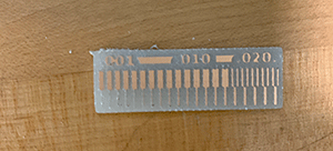
We then opened that file on the Roland mill software, Vpanel. Before changing anything on the computer, we had to set up the mill. We moved the bed all the way to the front and moved the z all the way up so we could successfully reach the bed. We took our material and stuck doublesided tape to the underside, before sticking that to the bed. Next, we took out the bit that was in the machine, and swapped it out for the one we were using. Now, we were all set to start with the software. We moved the origin to the proper position on the bed, and then set the z axis very close to the bed. Then, we untightened the bit so it touched the bed, before tightening it again, to set the origin for the z axis. We could then cut! The first step for the process of our test file is engraving. The first time we did this, our cut didn't come out successfully because the bed wasn't fully level. Our group just changed the placement of our origin on the material, and it ended up working out fine! You can see the result of this below.
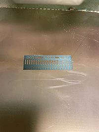
Once that was done and we vacuumed the shavings, and then switched the bit to the one that would cut. The xy origin we could leave from before, but we had to set the z again, so we repeated the process from earlier. After that, everything was all set, so we cut out our test file. Here it is!
Individual Portion
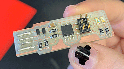
For the individual part of this week's assignment, we had to make a programmer with a PCB. To begin, I took the file for the Fabtinyasp from the tutorial section of the Fab Academy website and opened it in mods. I then changed the appropriate settings and saved the file to a usb. I transfered this to the computer in our lab that has Vpanel installed and is connected to the Roland mill. I changed the bit, origin, and z axis just like in our group test, and cut out my pcb.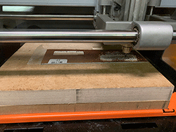
Once that was done, I went to our soldering station, and started adding the components to my FabTinyISP. The FabTinyISP needs 2 1k ohm resistors, 2 499 ohm resistors, 2 49 ohm resistors, 2 3.3v zener diodes, 1 red led, 1 green led, 1 100nF capacitor, and 1 2x3 pin header. When putting everything together, I started with the resistors and ended with the pin header! To add all the components, I used paste solder and a heat gun. Once all of the elements were added, I scraped off a bit of copper at the end of my pcb and added a bit of liquid solder to the lines at the end in order to strengthen the usb connection. Here are a few progress pics!
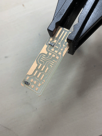
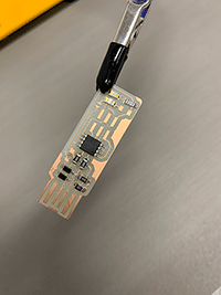
After adding the solder, I could test my connections! I plugged in my ISP, and the led lit up red, meaning everything was attached properly!
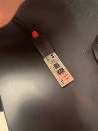
Since my board actually worked, the next step before I could program was to fix the solder jumper. Initially, I had added liquid solder to connect the copper plates, which let the led light up and signal that everything was connected properly, but there was no longer a need for this, so I separated the blob.
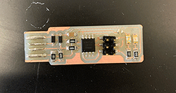
Now I could start programming! We used a Linux machine for this process in our lab, which I have 0 experience with, so that was very new for me. With the help of Professor Goodman, I followed his instructions and the Fab Academy tutorial through the process of programming my PCB. Professor Goodman had already programmed his own FabTiny, so we started with that. We checked that it showed up on the computer and the files were all correct before plugging my board into his.
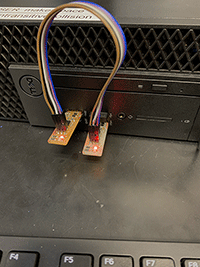
After that, we went through the rest of the programming steps, doing things like changing the fuses.
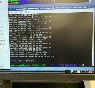
Once it was done, we realized that we forgot to name my file, so we started all over again, adding my initials.
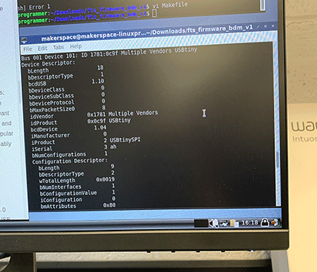
That step was the last one! My board was successfully programmed! We even used it to program another student in the lab's!
