Networking and Communications
This week's group assignment was to send a message between two projects and the individual assignment was to design, build, and connect nodes with network or bus addresses.
Group Assignment
For this week, our group worked with another group to send a message from one board to another. In my group, we ended up using my board from week 8, which we coded so that the led would blink after pressing a button on the other group's board.We also switched the roles of the boards so when the button on my board was pressed, the rotary encoder on the other board moved!
Individual Assignment
Since I'm not super strong with programming, I wanted to do something relatively simple for this week. My plan was to have two boards hooked up to the computer, and depending on the character I typed, a different board would blink its led. I could use one of my old boards for this, but had to make a new one for the second board I was going to use. I kept this one very simple. One slight complication was that we ran out of attiny 1616s in our lab, which is what I was used to using. I ended up using a attiny 402, which was the most similar to the 1616. You can see the pinout below.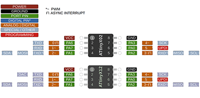
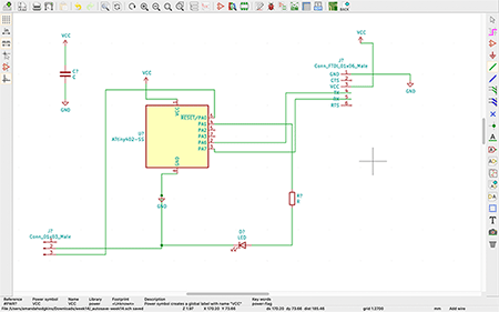
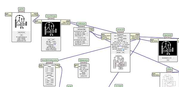
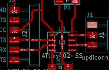
Just like in previous weeks, I made my circuit board design using Kicad. Here's the schematic.
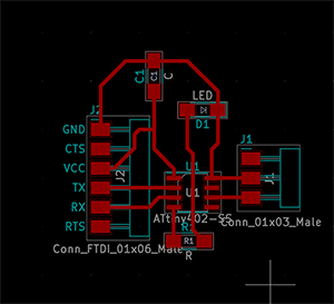
I then worked on the pcb, and then the outline of what would be the board itself.
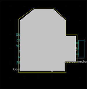
I then exported these as svgs and opened them in mods to prep them for milling with the Roland.
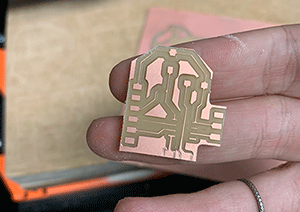
I prepped the Roland by taping down my material, changing the end mill, and setting the origin, and then went to cut!

The end result of my board wasn't great, but it was workable. My traces were extremely small, but still had continuity, and the bottom pads that you can see in the photo below didn't get fully milled out.
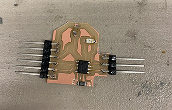
I fixed the pads by using a xacto knife to scrape away the copper connecting them together, which wasn't too hard. After that, I soldered all of the components to my board!
I came in the next day to code, and found that I kept getting errors when I went to upload code, both to my new board and the old one, even though the old one worked perfectly fine two days prior. After a bit of investigating with Professor Goodman, we realized that the adaptor cable was broken, so I switched it out for another. My old board worked fine after that, but I was still getting issues with uploading to the new board. I went to Professor Goodman again and he noticed that I never connected my programming pins to the power on my board. Although this sounded like a pretty big issue, Goodman and I got around it by connecting a wire from the vcc pin on the 6 pin header to the 3 pin header that it was supposed to be connected to. This worked and I was able to upload a blink code as a test!
Since both of my boards were working fine, I could now upload the code for this week's assignment! I started by testing it in Tinkercad before uploading it to my newer board. I altered the led pin number in the code and made it so that when a was typed into the serial monitor, that board would blink once. When c was typed, both boards would blink 3 times. This uploaded without a hitch, but when I went to type into the serial monitor, nothing would happen. After a bit of troublshooting, I realized that I had my tx and rx connected wrong. Tx was connected to tx and rx to rx, instead of switched.
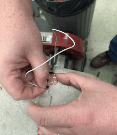
To fix this, I connected wires from the header to the cable, crossing the tx and rx wires so they were connected to the correct pins. That fixed the serial communication and you can see it on the one board below!
I then hooked up my second board, altered the led pins again, and changed the singular blink to happen when I typed b. I kept the c code the same because I wanted both boards to blink when that character was typed. I had to change the chip in arduino since I was going back to the 1616 for this, and it uploaded successfully again!
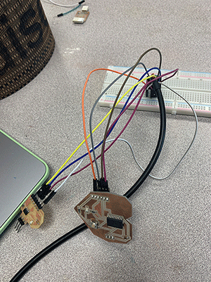
With all my code uploaded, I went ahead to connect both boards. I used a breadboard and connected each board in the correct orientation with wires. To do this, I plugged the adaptor cable into the breadboard and then used dupont wires to connect each pin to the corresponding on on my two boards (ground, vcc, tx to rx, rx to tx, etc). This worked fine for my old board, but since I had messed up my new board, I had to switch the tx and rx again.
Everything was all good to go, and it worked perfectly! The communication comes from the serial.read in my code and the char variable that I added, which, depending on what I type, changes how the leds blink on one or either board!