Computer-controlled Cutting
For this week, our assignment was to practice computer-controlled cutting using various machines/softwares. We had to do a group project by testing our laser cutter and vinyl cutting something, and then work on our own to make a parametrically designed construction kit.
Group Work
Laser Cutting
For this portion of the assignment, we focused on testing aspects of our laser cutter's performance like speed, kerf, power, and focus.After looking at other examples of how previous students did this portion of the assignment, our group decided to test the kerf using different sized circles and squares. We would then measure the actual size of the holes that were cut and compare them to the values we had actually made them.
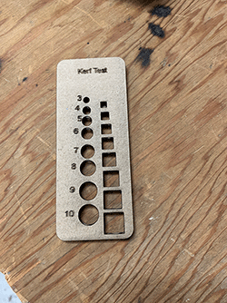
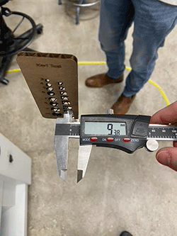
Here is a photo of one of my group members measuring the hole in our kerf tester.
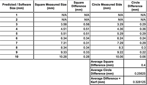
After getting our results, we then made up a table with all of the values and calculated the average difference of the circles and squares.
Since our laser is relatively old, the settings that we use for certain materials change over time. In order to test and see what works, my group created a swatch that we would use to document the settings we were testing on the laser cutter. Each time we went to got from Illustrator to Epilog with our swatch we would type the raster and vector setting values in their designated area.
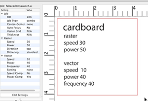
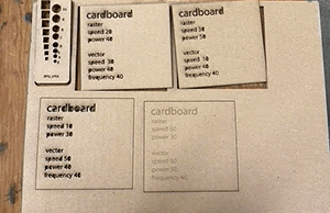
We did this 4 times, changing different values each time. As you can see in the image below, each swatch has varied success. Some worked well and were actually cut through, while others were still attached to our main piece of cardboard.
Vinyl Cutting
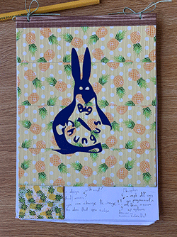
For the second part of this project, our group had to create a logo. After having a group name that was literally gibberish because we couldn't think of anything, Tuna came up with the idea of changing it to Big Chungus, which is a meme. We took an image off of Google and opened it in Adobe Illustrator. Using the image trace tool, we turned the image into a silhouette, since the vinyl cutter needs images to be only black and white. We then added text and saved our file.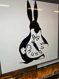
Next, we opened our logo in Sure Cuts a Lot, which is the software used by our vinyl cutter.
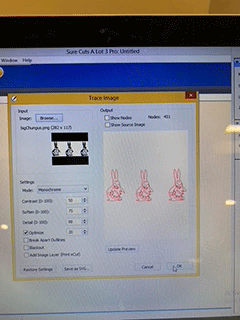
After getting all of our software stuff done, we had to set up the cutter itself. We put our vinyl in the machine and positioned the blade and grips to match the size of our roll.
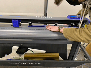
Now we were set to cut out our logo. After cutting out Big Chungus, we got rid of the excess vinyl on our section, by both simply peeling it off, and using an xacto knife for the smaller parts. Next, we took transfer tape and stuck it to our piece, making sure to smooth out any air bubbles that might've formed when putting these two together. After making sure the tape and vinyl were adhered correctly, we took off the backing of the vinyl and pressed it on the surface we were applying it to, again, smoothing out the air bubbles and making sure it stuck on flat. Once it seemed to be on our surface, we took the transfer tape away and had our final product!
Construction Kit
I was really excited for this project because I really enjoyed using Slicer last semester, but after hearing about the more technical parts of the requirements for this assignment, my idea didn't really adhere to that, so I ended up making something less exciting (I might make my design later in the year, but we'll see). After looking at other examples for this week, I decided to make interlocking shapes that you could build structures with. I played with something almost exactly like this when I was a kid, which I had completely forgotten about! Making the connection between these was super interesting for me, and after a bit of researching on Google, I found the exact toy (?) kit that I had! They were Octons!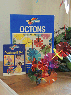
In order to put my own spin on this concept for this assignment, I decided to change the shape. For my construction kit, I decided to make circular rings. I used Fusion360 to create two circles that would make up the ring, and then added a short and skinny rectangle at the top of the outer circle, which would make the slot for the interlocking pieces. Using the trim function, I edited my sketch by getting rid of the lines of the rectangle that were outside of the circle. After that, I selected the remaining lines of the circle and used the circular pattern tool under the create section to add the slots around the rest of the circle.
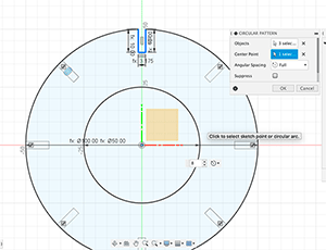
After I had my shape to my liking, I changed the parameters to all be variables, which I could change in the parameters tool.

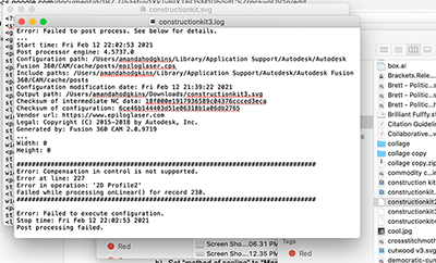
I then went to save my file so it could be opened in Illustrator and then laser cut, but I had a few issues. I initially went through the manufacturing workspace and selected the laser cutter as my tool, but that process didn't end up working for me. I also tried just saving my sketch as a dxf file, but that also didn't work. My file either opened and was blank, opened and had text instead of my text, or didn't open at all. The picture below is one of my errors.
After talking to other students in my lab, I finally got my sketch to open in Illustrator.
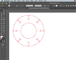
I then copied my sketch so that when they cut, I could see if my slots were the correct size for the circles to interlock. I went ahead to the print function in Illustrator and selected Epilog Engraver as the file destination. This is the software we use with our lasercutter. I made sure to select the correct bed size and put the orientation in the top left corner in the print settings. After getting all of that set up, I clicked print which opened my file in Epilog. Here, I could see a preview of my design, with red lines signifying where it would get cut. If I was engraving anything, that would show up as gray. I then edited my vector and raster settings for the material I was using, in this case, cardboard. Once that was all set, I sent the job to the laser, where I placed my piece of cardboard, set the origin, and focused the laser. I was all set to go! The first time I cut, my scaling was way off after going from Fusion360 to Illustrator, and my test circles were way too small.
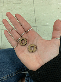
After manually making my circles larger in Illustrator itself, I cut them again. This time, my slots were too small, and the two circles couldn't fit together.
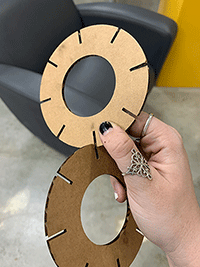
I went back to Illustrator and changed the slot thickness from 3.175 to 4.5 mm. This was a random guess based on how the previous thickness didn't work, but I went with it.
I printed out my second set of test circles, and they were perfect!
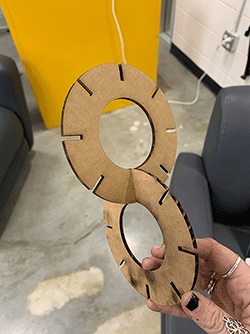
Now that I had gotten all the parameters right, I could print out the rest of the circles for my construction kit.
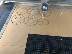
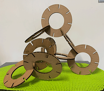
Once that was done, it was time to assemble. Here's my constructed structure!
