- Characterize the design rules for your PCB production process.
- Make an in-circuit programmer that includes a microcontroller by milling and stuffing the PCB, test it, then optionally try other PCB processes.
I've decided to use Brian's PCB board design as my programmer. You can download Brian's png design images from his website. First, I tried importing it to the Eagle software program. I wasted hours upon hours trying to get it to work on Eagle. Eventually, I decided to switch to the Mods program. It's much much better. I used this tutorial by Kris from Aalto FabLab to familarize myself with Mods. Even though my machine was different, the tutorial was still useful for me. After opening the PCB.png, I changed the settings to match the ones that I will be using. Finally, I ran both png files (traces and outline) through the Mods program and uploaded both of the G-Codes generated by Mods into the computer connected to the Roland milling machine. I used double sided tape in order for the stock not to move while drilling. Now it's ready to mill!
Unfortunetaly, I had only drill bits though, so I will try milling with a drill bit. I accidentally put the wrong size bit at the start so, I stopped the machine by lifting the lid, and changed the drill bit. Then I re-started the workflow again and it worked perfectly!
If you look closely at the video you can see that the drill bit is bending slightly. That's because it's a drill bit not a mill bit. Don't get the two confused. The drill bit is for drilling holes and the mill bit is for milling. This can make your bit break. *foreshadowing*
Once Brian's board was finished, I started milling the test board, to characterize the design rules for the production of my future PCB boards. This way, I can also see how thin I could have my traces when designing my PCB's. I already had the G-code for it since I had done it at the same time as when I did Brian's PCB. I established a new X/Y origin so that the machine would not cut over the area that I had already milled. I then started the trace milling for the test file. It worked perfectly at first, and engraved everything well. However, when cutting the outline of the board out, the drill bit broke! That's where my warning from before would have helped. But milling the traces worked well. Thankfully, I had what was most important, the traces.
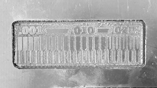
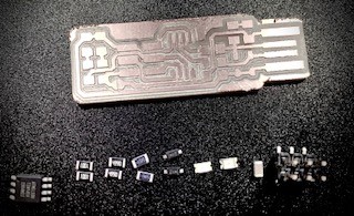
It's pretty good though, now I know how deep to cut and how thin my traces should be. The next step is to stuff the board, to solder the components on. So, I laid out my components and prepared the soldering iron and wire. It's time for soldering!
Soldering is melting a bit of lead or other easily meltable metal which fuses two metal parts together. Due to our location, electronic components are hard to find since they cannot be locally sourced and needs to be imported. I decided to practice soldering using some scrap components to start out. These components were through-hole soldered not surface mounted. I thought there would be very little difference, but there was. Through-hole soldering is easier than surface mounted soldering. But, I actually accomplished a good solder with the through-hole components!
When I finished soldering all the components on the scrap board, and felt pretty confident about soldering, I decided to start soldering my PCB. I laid out all my components in the order I would solder them, and cleaned up my workspace.
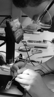
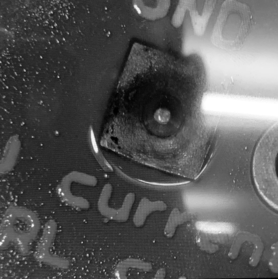
I started by soldering the ATtiny onto my board. I first soldered one side of the ATtiny and immediately had issues. My soldering iron's header was a bit too big for the ATtiny little legs. Suddenly, there was solder wire melted everywhere, the solder had flowed all over the board. My hands were also shaking all the time. It was really strange looking through a microscope and seeing my hand shaking. I had never realized that. Anyways, it was a complete disaster, the opposite to my through-hole soldering experience.
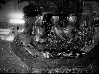
I spent an hour or two just soldering the ATtiny to the PCB. It was just not working out. Eventually someone in the lab suggested using Flux to get rid, or clean the soldering mess. I tried it out and it worked! After researching a bit more about soldering, I changed the tip of the soldering iron to a smaller tip, so to be able to solder the tiny components.
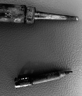
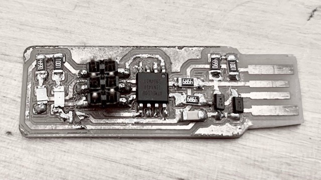
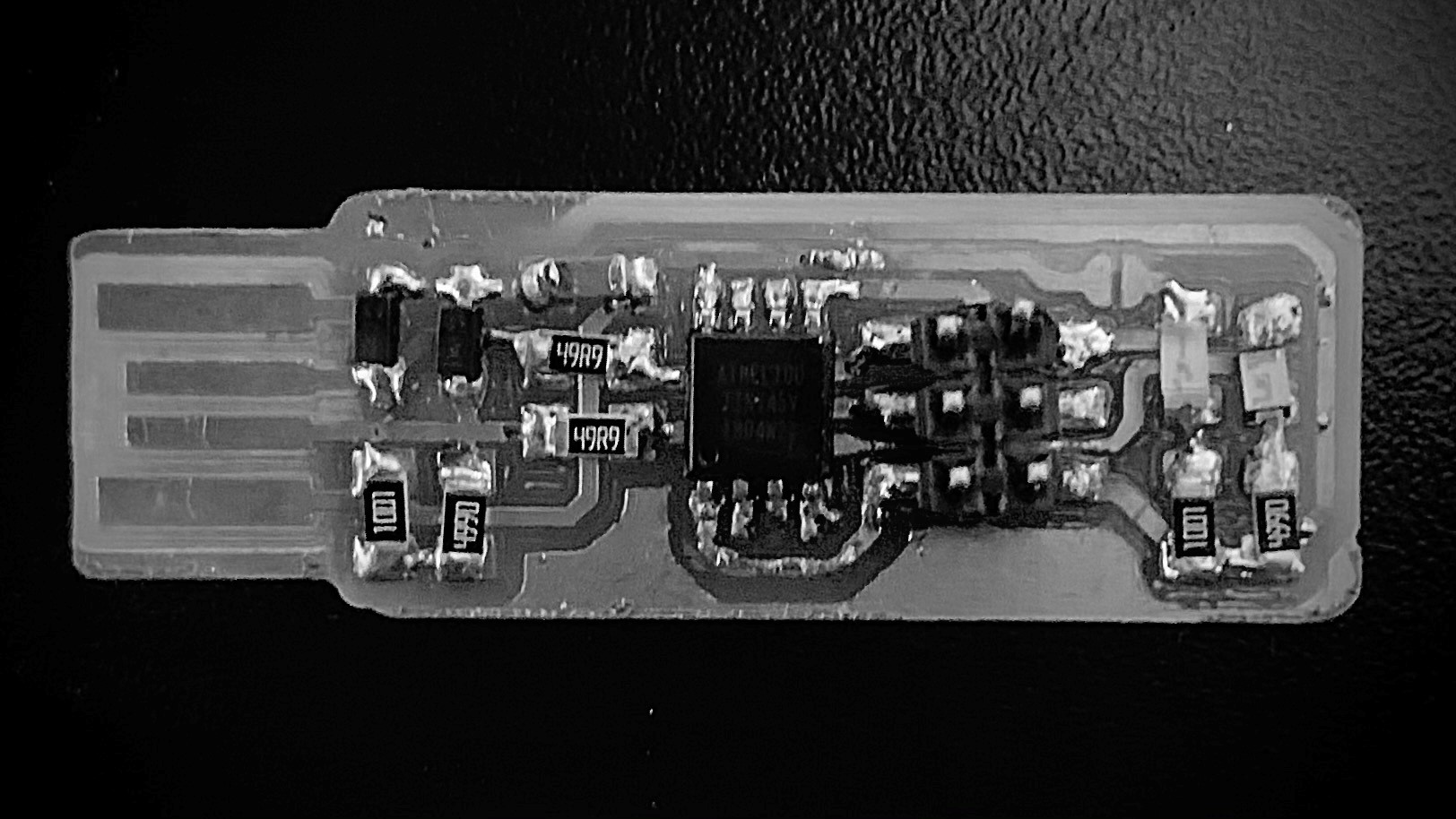
After changing the tip, and a good night's sleep, I fell into the rythm of soldering the tiny parts. I used tiny tweezers to hold my components down, heated the components and the copper, then slowly introducing the soldering wire. The rest took some time, but with patience and a bit of flux, I managed to get all the components soldered. My advice is, use flux, have the parts secured in some way (tape or tweezers), and use tiny tips with your soldering iron. That worked for me! My joints were very lumpy and not that shiny, but they worked, no shorts, which is the most important part! I cleaned the joints up a bit, by heating up the joints, and pressing the components down with small tweezers. Eventually, I got it all done, so now I had to double check for shorts.
I set a multimeter to the short-checking setting, where you take two different ends, place them on different parts of your circuit, and check if there is continuity. If electricity flows through those two points, the multimeter emits a sound. I checked all the different parts of the circuit, going over multiple times, and found no shorts! That meant that the PCB board was finished and ready to be programmed!
First thing to do is set up my development environment. We first need to download all the applications required for programming and to set them up. I used a Mac instead of my PC since it was easier. I downloaded and installed Crosspack. However, when downloading CrossPack I was not able to open it because it was blocked by Apple. Apparently, it came from an unidentified developer. I bypassed this by authorizing within the Security and Privacy/Advanced Settings System preferences of my computer. After that, it dowloaded without an issue.
I then downloaded and extracted Brian’s firmware code from Brian's Website. After extracting the firmware code, I opened the Terminal program and using the cd command navigated to the folder named fts_firmware_bdm_v1 that I got from his website. Then, following Brian’s tutorial, I attempted to run make. But it resulted in an error, specifically invalid active developer path and make: avr-gcc: Bad CPU type in executable. I searched for a solution and found a possible solution in Harm’s Fab Academy website. He recommended to try different commands which were:
brew install avr-gcc
brew install avr-libc
brew tap osx-cross/avr && brew install avr-gcc
But none worked because I had to install “HomeBrew”.
While attempting to install HomeBrew, the installation stalled, and when I wanted to re-install, it would result in another error brew install and brew update have the error: refs/remotes/origin/master': unknown revision or path not in the working tree. Apparently, it had problems overwriting an existing install that had a broken core tap.
With the help of my mentors, I found two commands in github that solved the problem:
rm -fr $(brew --repo homebrew/core)
brew tap homebrew/core
I then successfully re-installed HomeBrew with a command from HomeBrew's website
/bin/bash -c "$(curl -fsSL https://raw.githubusercontent.com/Homebrew/install/HEAD/install.sh)"
With HomeBrew installed I tried solve the error I had when running “make” again by using Harm’s three different approaches:
brew install avr-gcc - which resulted in an error
brew install avr-libc - which resulted in another error
brew tap osx-cross/avr && brew install avr-gcc - which finally solved the problem!
Now with the issues resolved I tried running “make” again. This time, thankfully, it worked, and successfully created a fts_firmware.hex file! This hex file will be the one used to program my ATtiny 45.
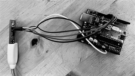
Following Brian’s tutorial we have to update the Makefile to tell the computer that I will be using an Arduino as the programmer to program my new PCB programmer. So I changed the line that says PROGRAMMER ?= usbtiny to PROGRAMMER ?= Arduino. I then plugged the board into a USB port on my computer using a USB extension cable, and connected the Arduino programmer to the ISP header on my PCB board.
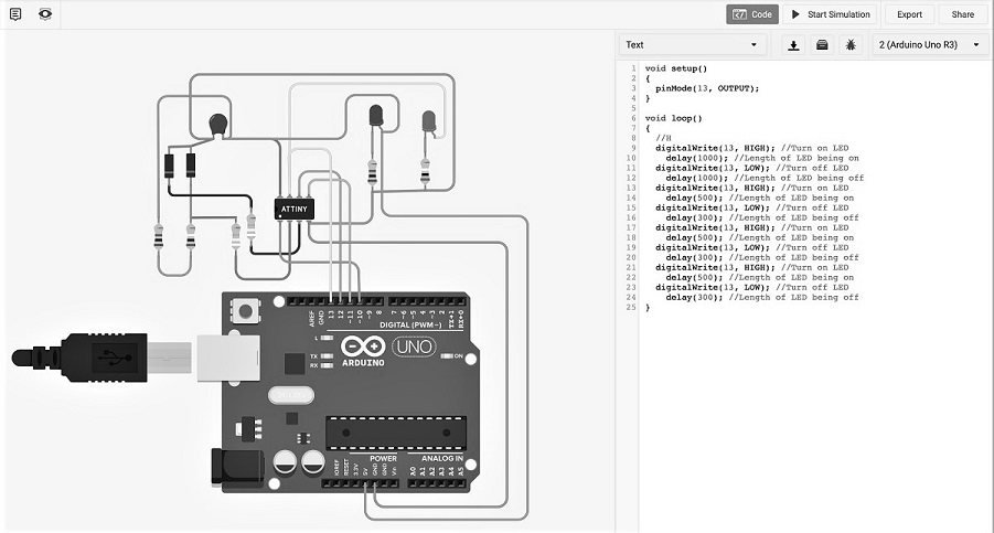
Next, I erased the programmer's chip's flash memory, and programmed it with the contents of the .hex file which I had created earlier. To do that, I needed to run make.flash. However, when I ran it using Terminal, it did not work... So, I checked the connections between my PCB and the Arduino, according to this list in order to make sure it was all properly connected:
PCB Header’s MISO to Arduino pin 12.
PCB Header’s SCK to Arduino pin 13.
PCB Header’s RESET to Arduino pin 10.
PCB Header’s VCC to Arduino pin 5V.
PCB Header’s MOSI to Arduino pin 11.
PCB Header’s GND to Arduino pin GND.
They were all properly connected and I still needed a solution to the problem!
My instructor and I decided to research for similar problems and found someone with the same error as me. Instead of changing the line that says PROGRAMMER ?= usbtiny to PROGRAMMER ?= Arduino. I had to change it to PROGRAMMER ?= acrisp, even though the port is called Arduino. No idea why, but I tried anyways. However, it did not work!
Salman, my regional mentor, recommended using the following command:
avrdude -c (programmer) -p (target chip) -P (Port) -v (verbose) -b (baudrate)
But replacing the bold and in parantheses portions with my relevant information.
This command checks that a connection is established with all the settings that I had. I continued with a trial and error approach changing the values until it eventually worked! I then, uploaded the blink script to test if the programming worked, and it ran perfectly
I wrote:
avrdude -c avrisp -p t45 -P /dev/cu.usbmodem14201 -v -b19200
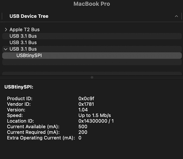
I couldn't figure out why it did not work, and went back to the lab to check for shorts using a microscope. Everything was properly connected. Then, as a complete surprise, when we tried the programmer on the lab computer it worked! Back at home I tried again, strangely it was identified in the USB port of my computer three-quarters of the time, and it would not work with a specific adapter. Fortunetaly, I got it to work in my computer although not reliably, even if it's moody. Finally!!! It works!!!
Brian Programmer Traces
Brian Programmer Outline