Table of Contents
Assignment Concept KiCAD designing Milling the PCB Sodering the board Programming the Board Design Files^
- Measure something: add a sensor to a microcontroller board that you have designed and read it.
- Probe an input device's analog levels and digital signals
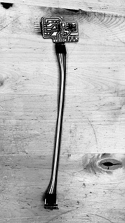
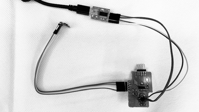
I want to design a PCB board for a VL53L1X Time of Flight sensor to use in my final project as an input device. It seems a good sensor to use because of its four meter range. I searched for a previous project that integrated the use of this Time of Flight sensor with the activation of motors/wheels as its output. I was happy to find that I could use the StroBot project as an inspiration which Omar AlDajani made. His Strobot, is very similar (in terms of sensors and coding) to what I am trying to achieve. Instead of rotating wheels, and to complicate things, I would like to activate a Strandbeest mechanism. I read the Time of Flight Sensor's datasheet and tried to understand how it works. As Omar did on his Strobot, I also decided to connect my sensor with cables instead of directly on the board, to offer flexibility on where I'm placing it on my DromeDroid. Most likely, it'll be separated from the electronics compartment at the front of the DromeDroid.
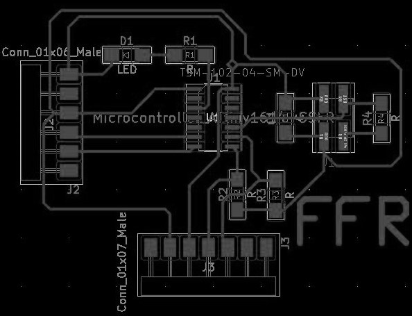
I started by making the schematic electronics design of the board, using the same Global labels as last week. I read the 1614 datasheet, and using the Pinout layout, I was able to start designing the input devices board.
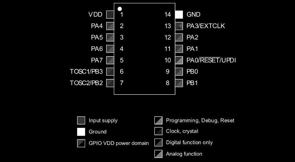
The Global labels made it easy and quick for me to design. The overall layout design of the board is like a breakout board, where I breakout the microcontroller's pins onto male connectors. This will give me more flexibility while troubleshooting programming.

After finalizing the schematic design, I started designing the traces. Everything was going well, until I had only one ground pin left to connect. It was impossible to connect, so I had to start the traces layout again.
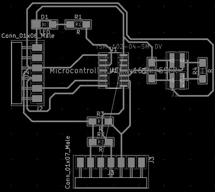
Trying again from scratch, resulted in a greater mess.
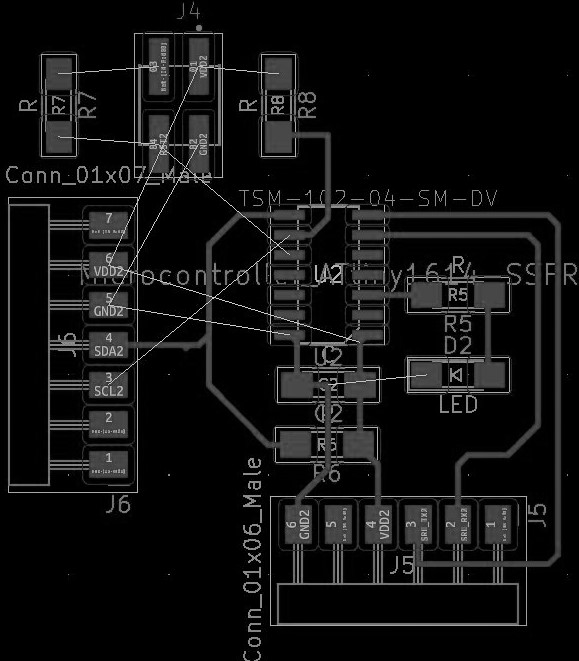
A bit frustrated, I got my instructor to take a look and together, we found a simple solution. It's nice to see things from a fresh perspective!
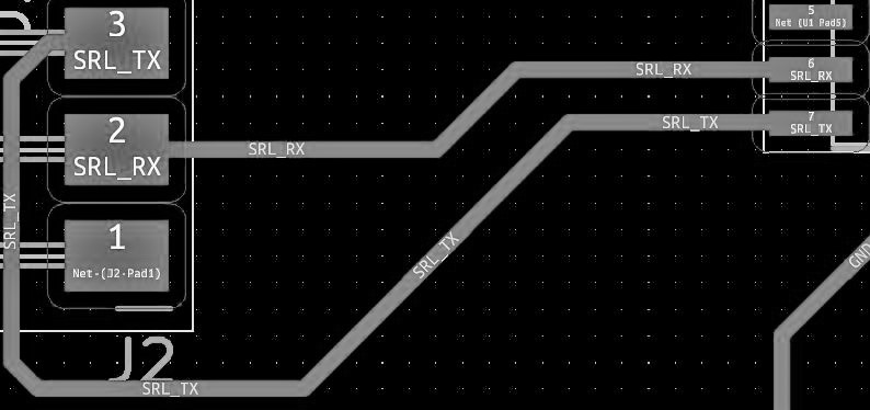
When looking through it one more time, I realized I switched RX and TX. I fixed the layout, but later realized that I had unconsciously undone it... when taking screenshots for the documentation, I undid the new design and forgot to re-do, so when I milled it, I realized I had an older version. *facepalm* Thankfully, because its a breakout design, it is easy to switch the cables, but I have to always remember to switch the cables.
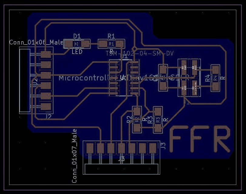
I then drew the border, margin, and edge. I ended up with a strange shape similar to a 'group' button in a drawing software. Now it was ready for mods and milling!
When working through mods, I found a weird bug that it would only make outlines the first time you ran the code. Luckily I found the problem, and got it done with the same tutorial as before. However, I did not notice that the amount of offsets were too small, which almost broke the board. But was able to modify that on time as well.
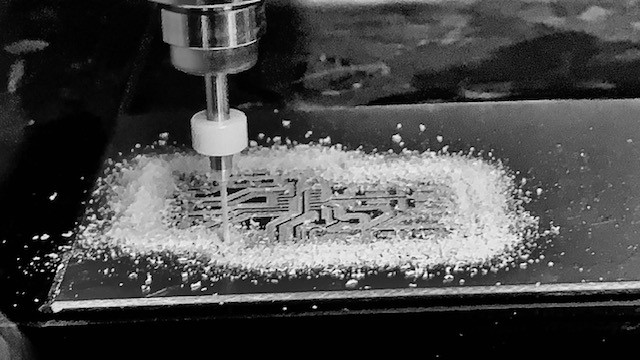
I started milling at 100% speed and with the same settings as usual, but someone at the lab had messed up the machine before I tried to use it and it broke a couple of my milling bits. Carl, in my regional meeting review told me that it was probably an issue with the spindle and the collet being off-centered. There was some evidence of a crash, so that probably caused it. I had a long online troubleshooting session with Carl and my instructor and we were able to fine tune the Roland milling machine again.
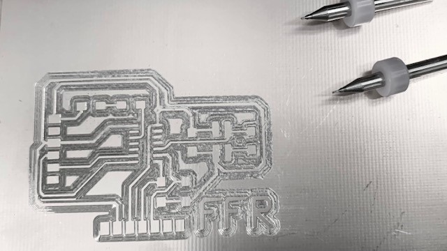
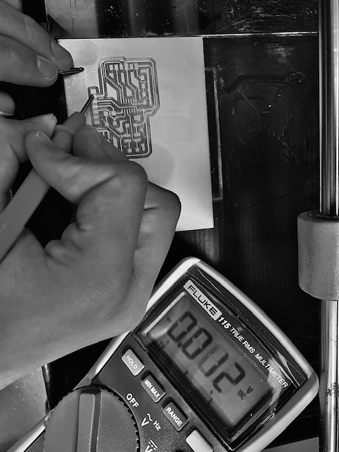
When it was finally done one end of the board was not fully cut, it didn't cut one of the edges as well. I probably didn't place the board on correctly or the bed was not alligned as a result of its prior crash. In order to salvage the milled board, I decided to adjust and lower the z axis to be a bit lower than originally, which would result in a deeper cut. This worked out. I then checked all the traces with a mutlimeter, and noticed that there were a few pads which were also shorting. Cutting these areas deeper hopefully would resolve the problem.
I milled deeper again, and it worked, there were no shorts. I have to now re-align the Roland's bed though. I then started cutting the outline, which unfortunetaly, did not cut fully, it was not deep enough. Luckily, I snapped it right out because the cut left just a tiny bit of stock on the bottom.
This is my third board, so I was initially not worried about soldering all the components, but the ATtiny1614 proved challenging. The pins are so tiny! I flowed solder over all the pads, and pinned the components down with tweezers, then heated the solder, and it flowed over the metal part of the capacitor. However when using this technique on the ATtiny1614, I burned one pad right off! This time it was the Reset pin, an important one!
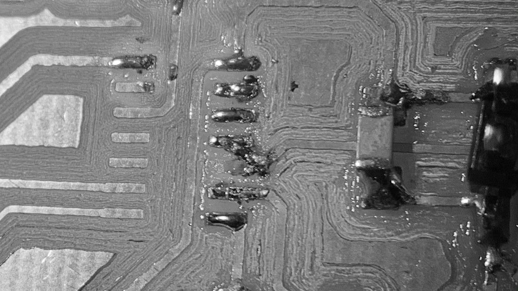
Luckily, I somehow managed to connect the solder with my shaky hands. I think that's the first time they helped, well they did eliminate a career option, I know I'll never be a surgeon! Anyways, I managed, so i got the rest completed, and when checking the board all the connections looked good!
I had some issues determining the anode and cathode side of the LED though, so I googled it and quickly found a good guide for SMD LED's and other SMD parts. Here it is:

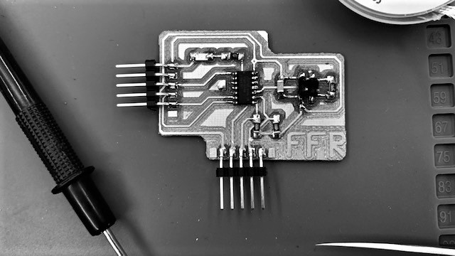
Once I got the LED soldered, the rest worked well, and my third custom board is now complete!
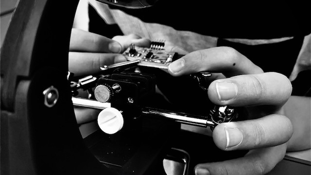
Programming! The fun part. This is where I finally see if my board will work. This week, I decided to design my board so that it's programmed with UPDI instead of an ISP, just to try it out. At first I was confused on how to do it with an arduino, and I started asking around for help, Adrian recommended that I should program it using an FTDI cable, my instructor had one from back when she was in FabAcademy, and I started using it. However, it was an older model and could not be used. I then fell into a period of stagnation, and started thinking about next week while asking for more help.
Eventually I found guide online, and started using it. I connected my arduino the right way, and connected my sensor as well. All the steps went by flawlessly, but when I had to upload the sketch, it gave me an error, 'HOST_USART' was not declared in this scope I have no idea where it came from. but it had never happened before. Anyways, I decided to have a meeting with Duaa, my regional mentor, and see if we could fix it together.
Once in the meeting, I noticed something strange, the error did not happen, but my board was sucking power like there was no tommorrow. Duaa and I started checking the cables and connections, and there were no shorts. However, I did notice I connected it wrong, so I reconnected the cables in the right way, and this time it worked! In this meeting I got a blink code running. Which means my 1614 works!!! Whohoo!
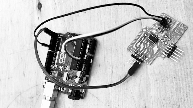
After the meeting, I started searching for the VL53L1X's arduino library. I found it with a quick google search, and found an example code inside. I decided to use it, but it was not working, and I got the error avrdude: jtagmkii_getsync(): sign-on command: status -1 arduino Eventually I traced the error, it's because the RX and TX are connected when trying to upload the code through the arduino. So I removed the RX and TX cables for the uploading and it uploaded well this time.
However I got nothing on the serial monitor. I decided to try a random serial monitor code just to see if the serial monitor works. It was just the word hello being printed. This did not work either. So, I got in touch with Duaa again. (She's a lifesaver) She had a theory about the jtag2updi program that allows me to upload the code. Maybe it was taking to much proccesing power, and the RX and TX did not get sent back. So I tried uploading the code to the ATtiny1614, then uploading an empty code to the arduino and tried again. It worked well, the only issue is that it's quite a hassle to set up and every time I try to revise the code.
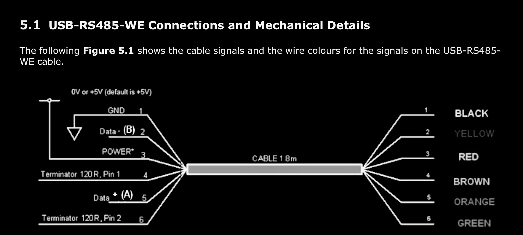
After asking around some, I found an FTDI to USB converter! I borrowed it for a bit, and got a good connection working. It's so much easier to run and program with, and I easily got the blink code running. I had a slight moment of confusion about the connections on the cable, but after revising the datasheet I'm good.
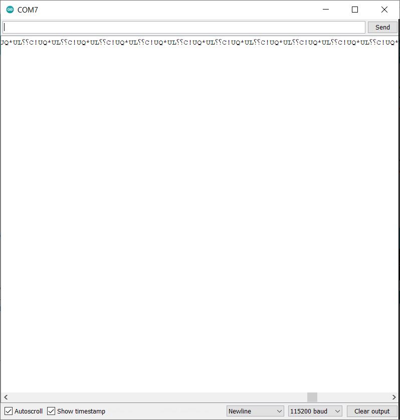
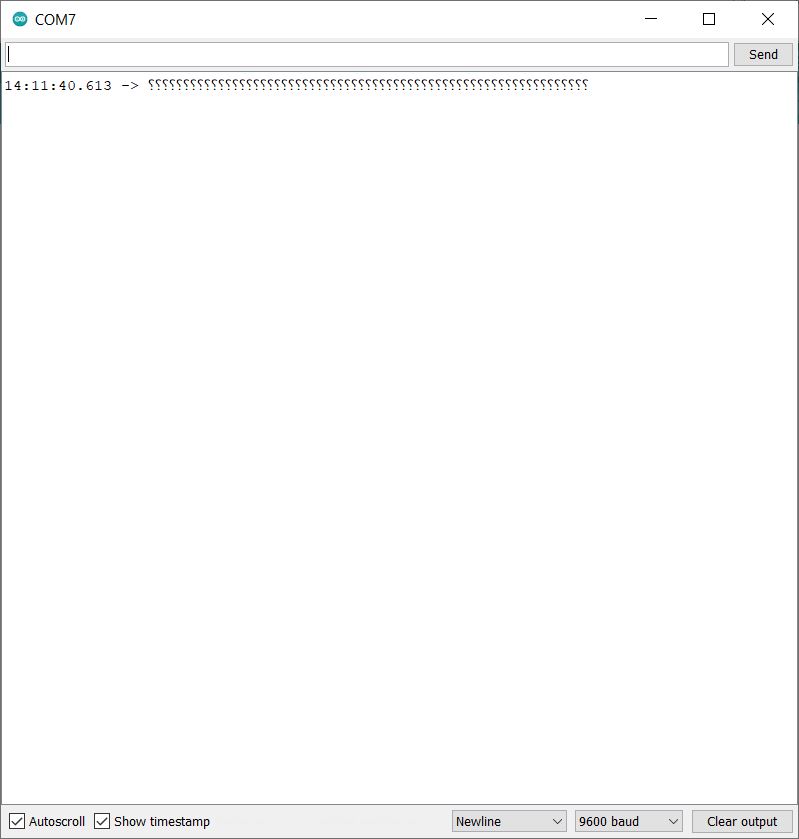
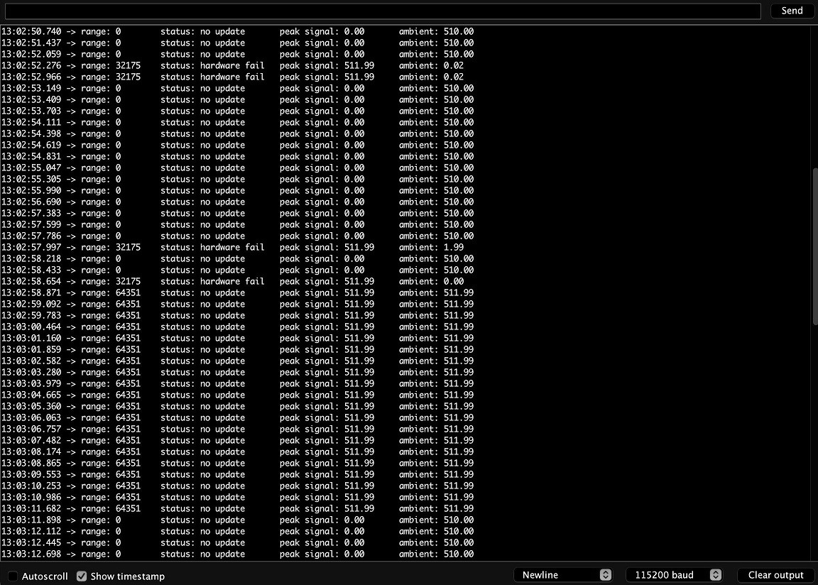
Now that the serial and the uploading was working well, I decided to upload the sample code from before. It uploaded well, the serial monitor posted what I had it do at the start to check that it worked, and... The sensor was giving time-outs all the time. Why does this not suprise me? I found another code that gave more detail, but it gave the equivalent of a timeout as well. Except for a brief flash of what seemed to be the right measurement, it was not working. But at least we got something! I'm close on this one.
After all the Time-outs, I was worried the sensor was broken, so I plugged it into the arduino's equivalents of SDA and SCL and tried it out. At first it did not work, but then, while showing that it did not work at the regional review, it sprung to life and gave accurate reading that made sense!! The sensor works, now I need to get it running with my board. The next time I tried showing it working, it stopped after a bit. That was strange, Duaa suggested I prop the sensor so it's not moving around. Which I did, and it worked perfectly.
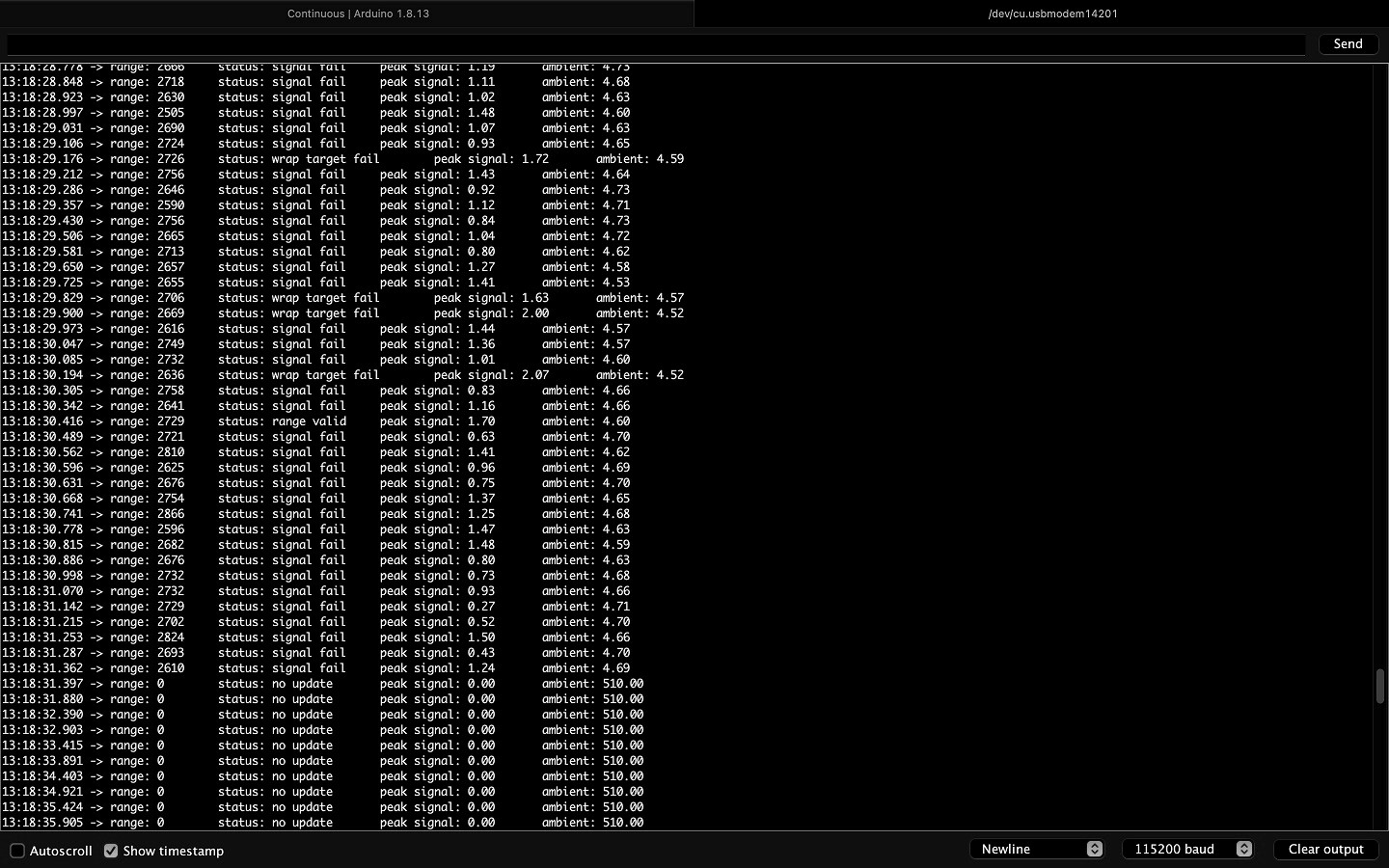
In the picture you can see it failing when I move it. So now I know not to move it. Unfortunetaly, it was not working reliably with my board.
At this point, I designed and milled another board to use for the final project. This new board worked and was capable of communicating with the sensor and the serial monitor without any problems!