- Do your lab's safety training, test runout, alignment, speeds, feeds, materials, and toolpaths for your machine individual assignment.
- Make (design+mill+assemble) something big (~meter-scale).
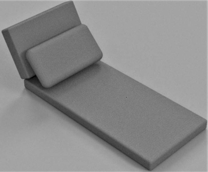
I love reading, and I have a specific corner in my room where I read, but I'd like something bigger and better. I want to design a lounge chair, or day bed for me to be able to read in comfort.

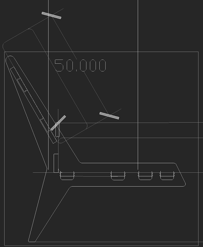
I want to use the same cushions that I currently have, so I measured them, and 3d modelled them in Fusion360. I then did some comfort tests, yes they were as fun as they sound, testing different angles for my cushions and I found the perfect resting angle for me, 60 degrees.
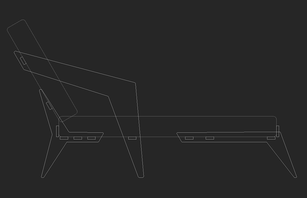
I started brainstorming a design idea. To kickstart my brainstorming, I went scrolling through Pinterest, looking for cool ideas of existing similar projects. Eventually I decided on a geometric-ish design approach. I decided to use Auto-CAD to design it at first, as I had more experience with it, and I had some time constraints. I re-modelled the cushions, and I designed a frame shape around the cushions, making multiple designs and trying to make it as cool as possible.
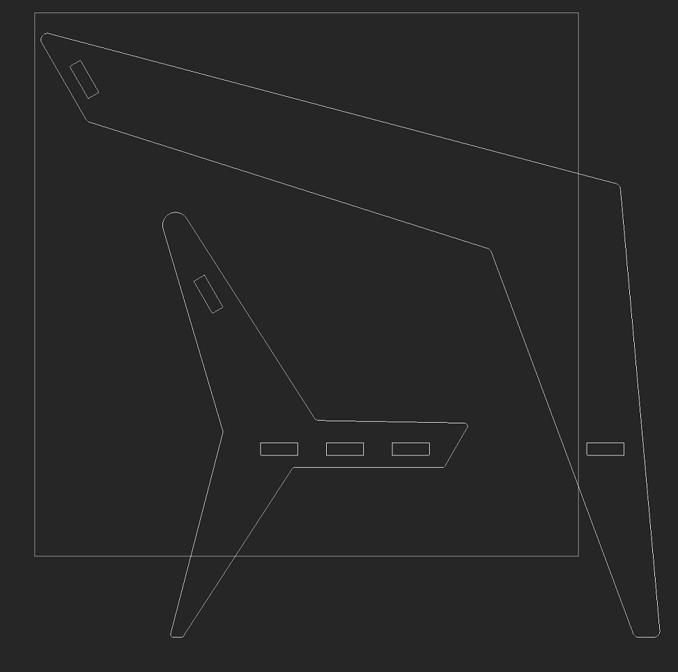
After finishing a design with which I was happy, I tried to fit my design within the cutting area of the cnc milling machine I am to use, but the biggest design piece did not fit within this area:
I then started to redesign and resize all the different parts of my design so they would fit within the cutting area of the machine:
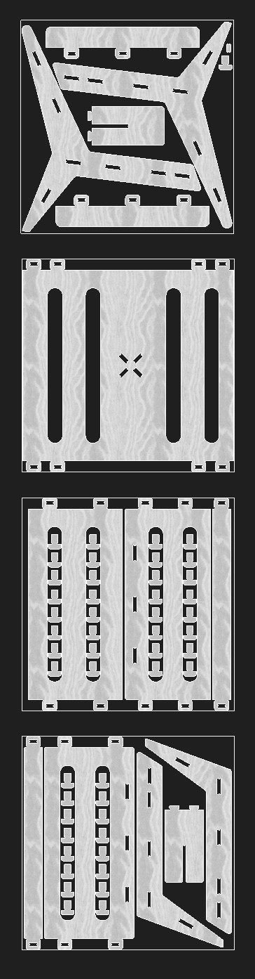
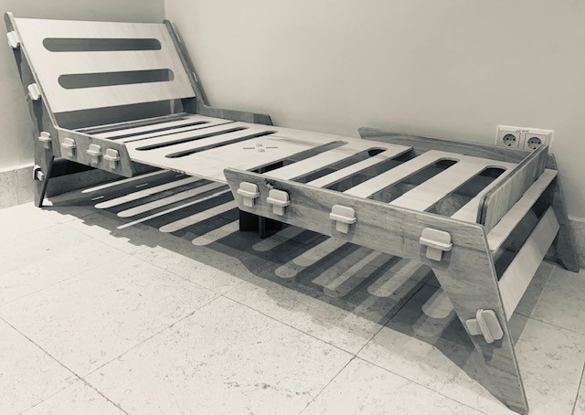
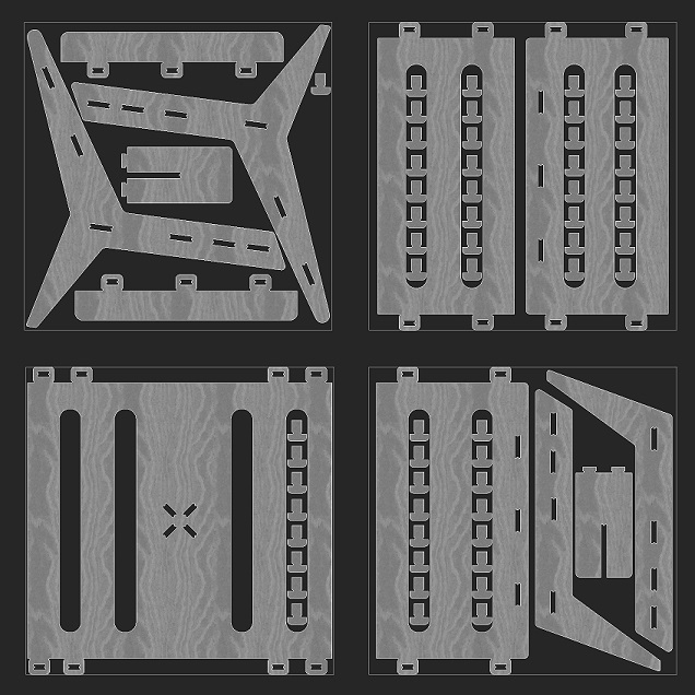
I then arranged all the pieces and they were able to fit within four panels of 32" x 33" cutting area, equivalent to two 4'x8' plywood panels:
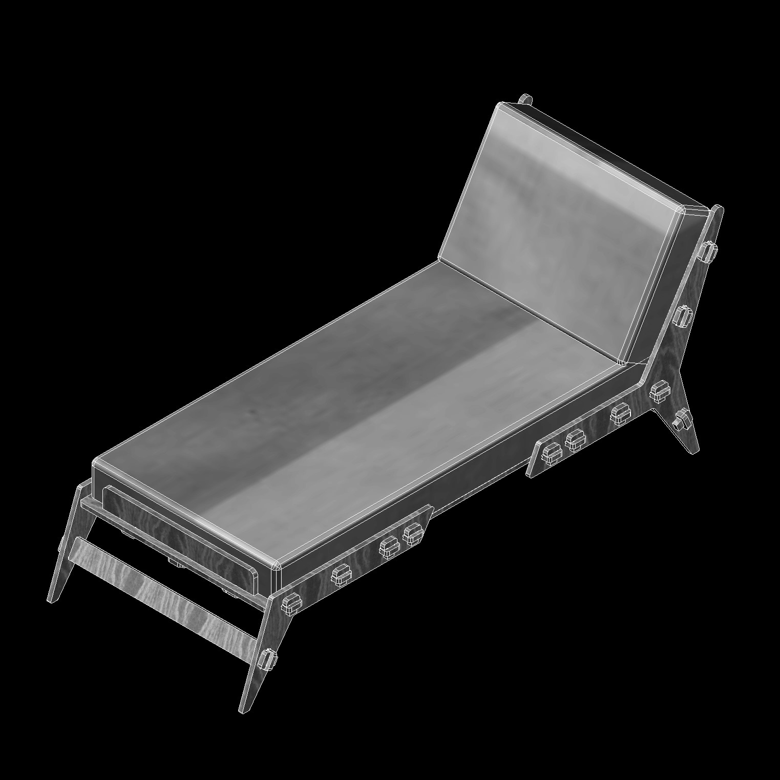
I test-fitted the design by arranging the different parts in a 3D model. This proved to be a great idea as a proof of concept and I found some errors that were generated when I was re-sizing my original design. I then was able to fix the components in the 2D design and re-arranged the parts.
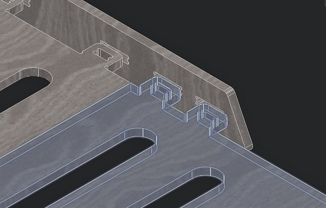
I test fitted it again within the 3D model and it works perfectly!
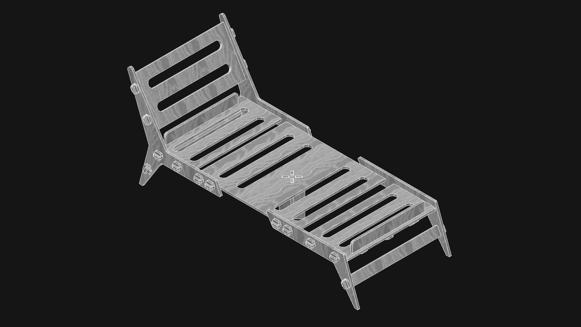
My 2D and 3D model designs are complete! All I have to do now is to start milling.
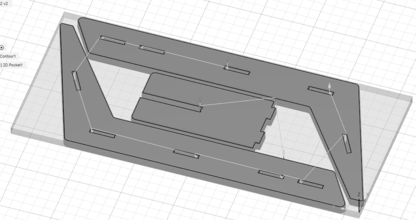
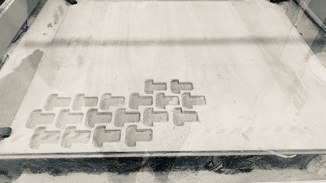
Once I had the design complete, I needed to generate the toolpaths for the g-code. I started by exporting everything from AutoCAD to Fusion360. I then began to assign my own custom tool, making it the same as the one I was using in real life, a 1/8" milling bit. Then, I established the rest of the job setup, setting the stock size of the corresponding wood board and the job's name. I then pre-viewed my first toolpath, selecting the order of how the job was to be milled. First I milled the pockets, which is where the connecting pegs would go into. I selected the toolpath to start at the center of the board working its way outwards. When selecting the pockets and contours with its designated tool I made sure to mill in multiple depths so that it would cut it in layers without stressing the mill bit. Then, I repeated the process for the four different boards I am to cut.
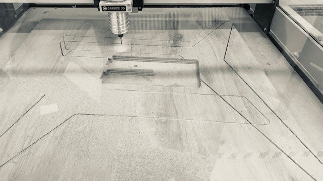
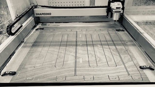
The CNC machine I will be using is a Shapeoko XXL. It is basically a drill controlled on its three axis. The machine is not complicated to use. You have to insert and secure the desired milling bit and then establish the job's "z" axis depending on your material height and the job's "x" and "y" axis. Once the machine is ready with the established axis, you need to generate a g-code of the job you are to cut using any g-code generating program. In my case, I generated the job's g-code using Fusion 360. The Shapeoko reads the g-code with its own program, Carbide Motion.
While milling, it is important to always keep the enclosure of the milling machine closed so that nothing interferes or gets tangled with the rotating motion of the milling bit. As with the use of many other machines it is also recommendable to wear safety glasses. If for some reason you need to access the milling area, please make sure that you turn off the milling spindle beforehand. Also, when starting to mill, and in order to not break the milling bit, I reduce the plunging speed at the beginning of the job. According to how the milling is going, I slowly increase the speed to 100%. It is important to always remain next to the machine and monitor its progress, making sure the milling bit doesn't break and that in effect the milling is progressing as it should.
Because I am building a lounge chair, I wanted my pieces to be as big as possible. I researched the machine's cutting size and sized my design accordingly. I decided to have my design up to the machine cutting limits of apparently 33" x 33". The machine started milling a center piece perfectly. Then it started milling the leg frames, which are "y" shaped and up to its cutting area limits. To my surprise, the machine did mill the first pass perfectly but on its second and third pass it did a strange offset on one of its axis, the "y" axis. It decided to shrink the job on just the "y" axis. This basically ruined the wood piece but was indeed an interesting problem. I then decided to do a "dry run" of the job and figure out its true cutting area. The result was a reduced cutting area of 30.5" x 32". I then had to re-adjust my design files to this new reality.
Once the actual milling size was adjusted to the design files the milling continued without problems. I first milled one of the pockets to test fit the wooden peg, and it fitted with a bit of sanding, so I proceeded to mill. It took several days as my design involves many pieces. But the results were as per the design.
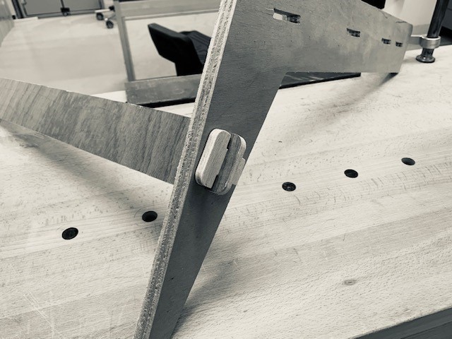
Planning ahead to when I go to university, I want to be able to take my lounge chair with me, and require it to easily disassemble and be easy to pack. For these design requirements, I devised for the design not to have any screws and for it to be easily assembled using pegs. The design and assembly ended up being like creating a puzzle.
I did have to file a bit all the edges by hand including the grooves for the connecting parts. After which, I sanded all the pieces so the wood would feel smooth.
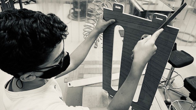
I tested interlocking some parts as I sanded to adjust them accordingly. This took a bit of time as well and thankfully my siblings helped with the sanding!
It was indeed a long project but a successful and useful one!
Lounge Chair Base 1 Design File
Lounge Chair Base 2 Design File
Lounge Chair Base 3 Design File
Lounge Chair Frame 1 Design File
Lounge Chair Frame 2 Design File
G-Codes
Lounge Chair 1 g-code
Lounge Chair 2 g-code
Lounge Chair 3 g-code
Lounge Chair 4 g-code