Table of Contents
Assignment Designing in KiCAD Milling the PCB Sodering the board Programming the Board Design Files^
- Add an output device to a microcontroller board you've designed, and program it to do something.
- Measure the power consumption of an output device
For this week, I'll make the motor driver board for my ice shaving machine that I did not complete that week. The design of this board will help me understand motors as output devices which I will also use in my final project. I decided to base my board off Neil's motor driver board, but editting it and modifying accordingly to fit my purposes. I opened the board and decided I would add a button to the ATtiny 44 and an LED between the Out1 and Out2 of the Motor driver, so that when it outputs electricity I have a visual indicator. I then started researching about motor drivers and the board, and found some information on why the board is the way it is.
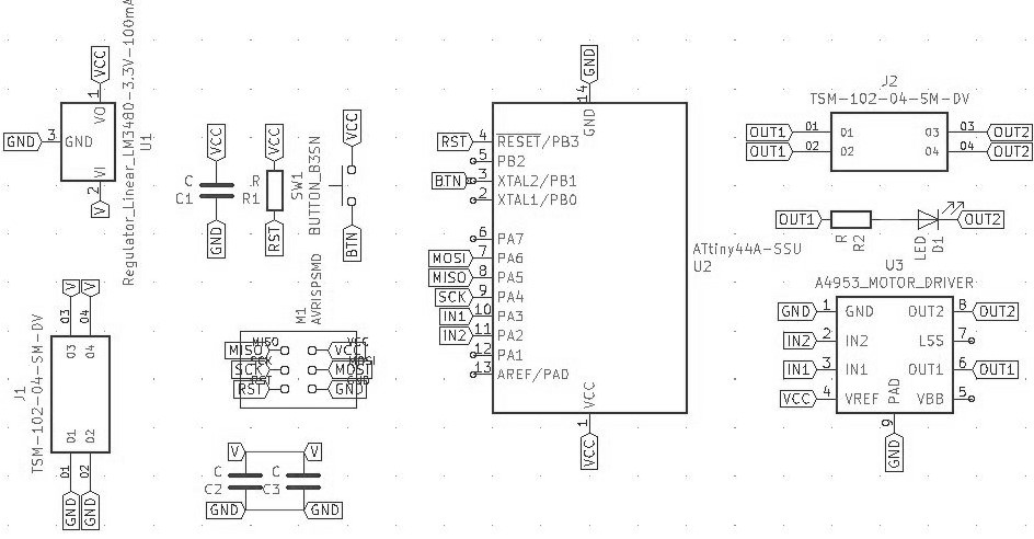
- The reason you need two chips, one motor driver, and one microcontroller, is that the microcontroller can't get enough voltage to control the motor. It's like a gigantic water wheel being driven by a small stream of water, the small stream of water from the microcontroller can only turn the water wheel of the motor driver, which then sends the big stream of water to the motor's big water wheel.
- Some components require other components such as resistors or capacitors based on their datasheet. For example here's why there are 3 capacitors, the 5V voltage regulator requires a 1 uF capacitor, and the Motor driver requires 2 capacitors in parallel, because "The load supply pin, VBB, should be decoupled with an electrolytic capacitor (typically 100 μF) in parallel with a lower valued ceramic capacitor placed as close as practicable to the device. " Which is written in the datasheet of the motor driver.
So then, I began designing my board. I got all the parts except for one. A 2x2 male header connector. For some strange reason it was not in the fabacademy kicad library nor the digikey library I downloaded. So I went on the hunt for it. But I could not find it in the many libraries I downloaded. I let it be, and continued 3D printing. Afterwards I started looking again, and asked my regional mentor, Duaa, luckily she quickly found the part in snapeda and I quickly downloaded it. Then I started making the schematic, but it became a mess in minutes. I could not find anything or check where things went. Then, I remembered there was some way to have no wires at all, so I started searching, and found an easy to understand guide on Nadieh's Documentation it's really good, check it out! So I used Global labels everywhere and had a nice neat schematic!
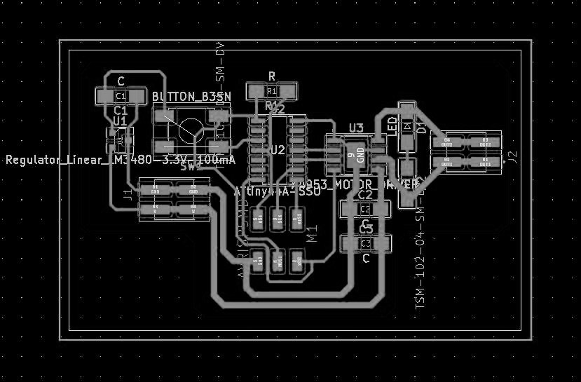
Making the layout was simple, I have done this before, after an hour or so, I had an efficient compact, and neat little board, this time in the shape of a very short T. I exported it as an SVG, and it was ready for mods.
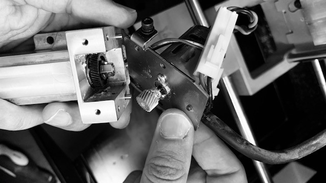
First I ran it through mods, this was the same as all the other times I did it. I used the same settings as always, and started the CNC. This wasn't too easy, I broke 4 bits before I decided that I should fix the machine. In the regional review, I asked Carl to help us through zoom. We got on a call and started fixing the machine. At first I thought it was the broken collar. Which looked damaged, but carl said the problem was in the gearbox.
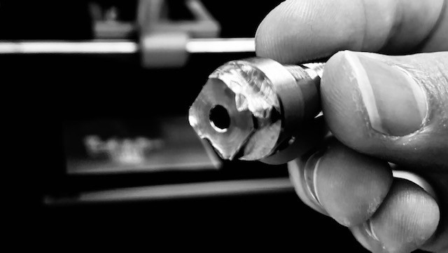
So we opened up the gearbox at the top of the spindle, and tightened the nut that helps the spindle be in place. This stopped the spindle from moving along the linear bearings, and causing small fluctuations in the cut that can break the milling bits.
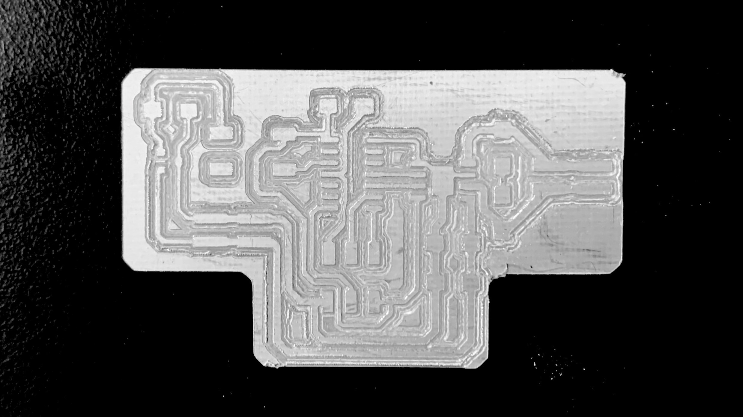
I then tried again, and it started to cut beautifully. I left it running at 10% speed overnight out of over cautiousness, and in the morning I had a working board!
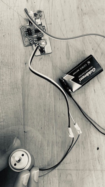
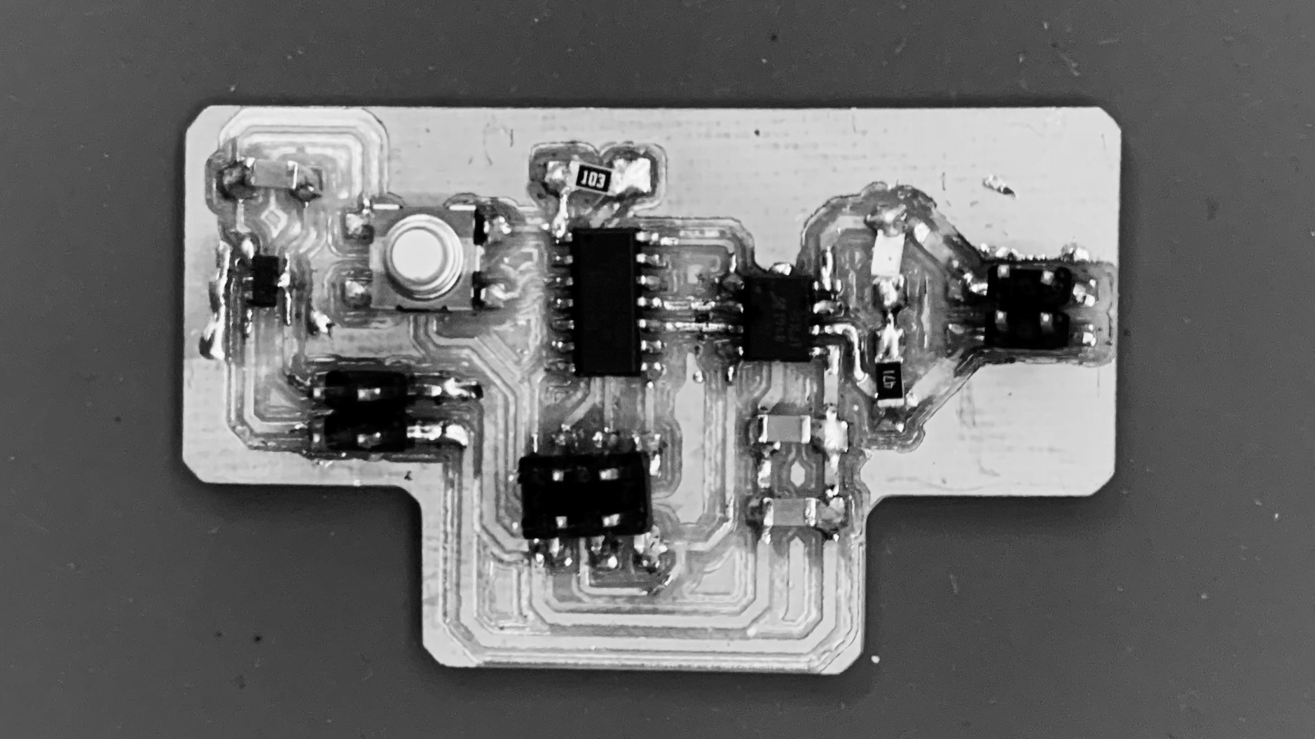
Stuffing the board was uneventful except for one part. The headers were causing problems for me, they would move around and be finniky, I needed to hold them down with a third hand. Anyways, I got it done in the end, and everything looked right.
Programming the board was pretty hard, as I only had one day, and I did not understand how to use the motor driver. I tried Neil's code, but it did not work. I didn't get not even an error message. So I decided to just try an ordinary blink code to the pin that connects to the motor driver, surprisingly it worked! I still did not understand how to make a PWM signal though. Now I tried to get it to work with the button, but for some reason it did not work. It would start randomly which is strange. I think I might have the wrong pin or a short somehow.
Another thing that was strange is that the voltage regulator got very hot whenever the arduino was connected to the board. I switched regulators, to a 5V one, and it still got hot. When it was battery powered though, it worked fine.
I did some research on the motor driver I am using, and found the link to it on digikey. I read a bit on the datasheet and started to understand what was happening. The motor driver has a few pins for power, which can be used for more complicated things, but I was intrested in IN1 and IN2. These two would control which way the motor is going, if IN1 is on and IN2 is off, it would go forwards, and it would go backwards if IN2 is on and IN1 is off, which is how I can control the direction. These were the two pins connected directly to my board which is how my code works. I would turn IN1 on and off, at intervals, and it would go forward at those intervals. So that is my code explained.
I also looked into my motor, and found the website which links to the datasheet here. There was not much detail, but I found out that my motor handles a maximum of 3 volts, and a macimum of 110 millamps. So I could have just powered it directly from my microcontroller! But still, the motor driver was a useful exercise.
I was confused about PWM, so I searched it up a bit. The full name is Pulse width modulation, basically, instead of a current being full on or full off, the motor driver can turn it on and off really quickly, in pulses, which limits the power, the longer the pulses when it's off, the less power goes through, those cycles are called duty cycles. Which is how the motor can go faster and slower, and not just on and off. Apparently it can also be used in telecommunications, to transmit data quickly, which is pretty cool.