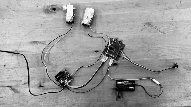
The electronics of this project is relatively simple. I am going to make one central breakout board, which will control everything. It will have enough room for up to 4 sensors and 2 motors. It will use an ATtiny3216 to control it, as it has the perfect amount of pins that I need. I also want to have the possibility to connect an LCD display if I ever need one. I will also be using a L298N motor driver, as it can drive two motors at once and I know how to operate it.
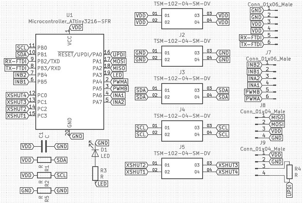
So, I started designing the board in KiCAD, as I want to program it with my new FTDI cable, I put the 4 pins neccesary for UPDI programming, (RX, TX, VCC, and GND), I put an LED with a resistor for debugging, a connector for SDA and SCL, another one with RX and TX to communicate, and then the 6 pins for the motor driver. Finally, I added a four pin header for each of the five pins neccesary for the sensor to communicate. All the pins were connected except for the XSHUT as it needs a unique pin on the ATtiny3216 for each sensor. I used the global labels for this part, so it was looking good.
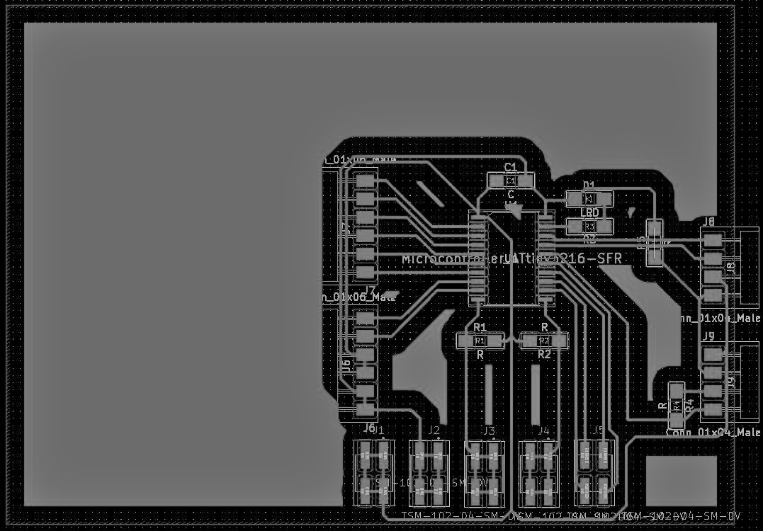
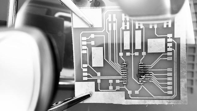
I made my traces quickly and easily, they were all straight lines, and there was just one part where I added a jumper, but everything was very nice and tidy.
I documented the details of the etching process in wildcard week, but I'll write the few mishaps I had with making this board. For my first board, I covered up the extra area in Coreldraw, so it was not very clean, but I got through the etching process quickly.
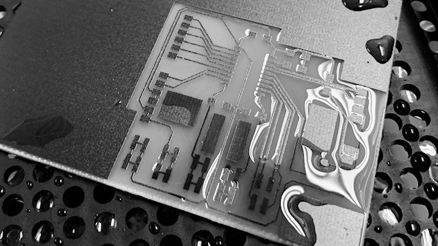
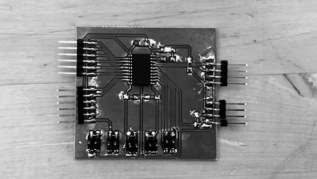
However, when I brought it home, and started sodering, I burned one of the pads off. After this, I always kept the temperature low in my soldering iron.
I made another board, and this time managed to solder it well, and ta-da! My board was finished!
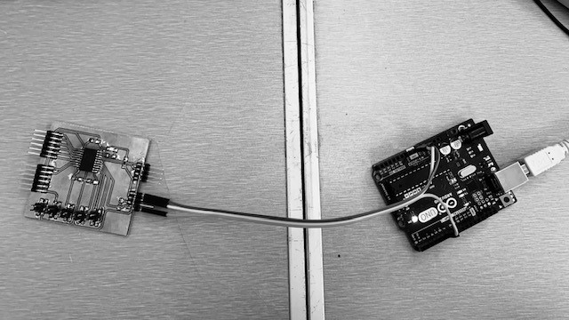
I started out programming my board with the arduino, using the reset pin for UPDI programming. This worked okay, but it was always a hassle to upload new codes, as I had to remove the jtag2updi code from the ardunio and reprogram it every single time.
Luckily, at the start of my coding process, I switched to the better FTDI cable! This was much simpler and quicker, as the Arduino IDE spoke directly to the board, and it was simple to set up!
I started my code by doing the classic blink test, which worked perfectly. I then wanted to try out my sensor, as it's a piece of equipment I was already familiar with. Suprisingly, I uploaded the code, and it worked perfectly! I was getting good readings from the sensor easily. I think I used up all my bad luck with that sensor in the input week. Anyways, I completed that bit.
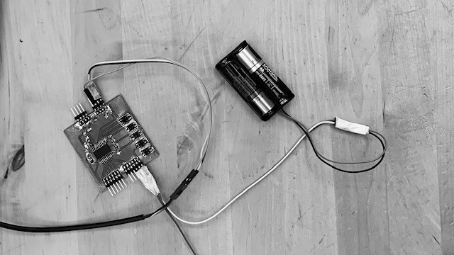
Now I wanted to program with the motor driver. The motor driver I decided to use was a comercial board, specifically the L298N motor driver. It has 6 pins as an input, PWMA, INA1, INA2, PWMB, INB1, and INB2, 3 pins for each motor. The PWM pin takes the input of how much current it should output to that motor, and the IN1 and IN2 serve as the logic. If the IN1 is one and the IN2 is off, it goes forwards, and if the IN2 is on and IN1 is off, it goes backwards. If both are on or both off, the motors are off. So I connected the pins, and saved the numbers as variables in my code, so I can refer them as INA1 or PWMB instead of pin 16. Credit to Duaa forhelping me in this one!
Using this information, I made a quick code that turns on each motor independantly. By the way, I'm using the COM-Motor01 as my motor, specifically two of them. Anyways, I used analogWrite, a command in the arduino IDE that allows you to output specific PWM signals, you put a number from 0 to 255 which output a two-hundred-five-ith (1/255) of the voltage you are using for your board. So I could control the speed easily. I did have a slight error though, as my motor drivers works with 5 volts, and my board with three, I can only go in three fifths of the maximum power, but that's alright.
I then had the motors move forwards, backwards, or stop depending on the distance between an object and the sensor. This I did by analyzing the incoming signal from the sensor, and powering the motors accordingly.