- Design a machine that includes mechanism+actuation+automation
- Build the mechanical parts and operate it manually
- Document the group project and your individual contribution
I sat down with my group which is me, myself and I (I will be doing this week alone, as I am the only student in the lab (for now)). Suprisingly we all had the same idea, a Piragüa making machine!
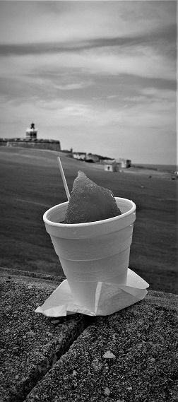
Piragüa is a Puerto Rican snowcone, sold by street vendors on the side of the road. Traditionally, piragüeros use a hand ice shaver to scrape some shaved ice from an ice block. Then, it is inverted into a paper cone and given a pyramid-like shape. Hence the name, pira = pyramid and agua = water, Piragüa. The Piragüero then drizzles some flavored syrup to give it some taste! Due to the pandemic I have not been able to indulge in some for almost 2 years, and I crave for piragüas! Therefore I am making my own mass producing machine, to have as many piragüas as I want.
Unlike modern snow cone makers, the piragüeros usually shave by hand in a linear movement. Remaining true to heritage, and in order to simulate the linear shaving that is traditionally used, I will be converting the motor's rotary movement to linear movement in my machine. So, I started drawing my first concept design to have a rough plan on what I am doing.
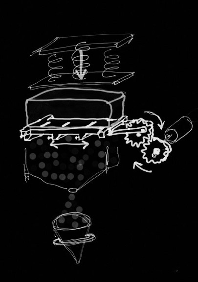
As you can see in the concept, I started out desining with a crank and slider mechanism. But after some internet searches, I found that using a Scotch Yolk mechanism would provide multiple advantages over a crank and slider. Such as providing a smooth and constant speed and the displacement and acceleration is slightly smoother.
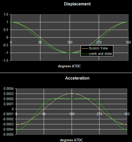
Photo credit wikipedia.
I decided to 3D Print most of my parts as well, because I want to take advantage of cool curves and be able to go wild in Fusion360. Speaking of Fusion360, I have to start modelling now!
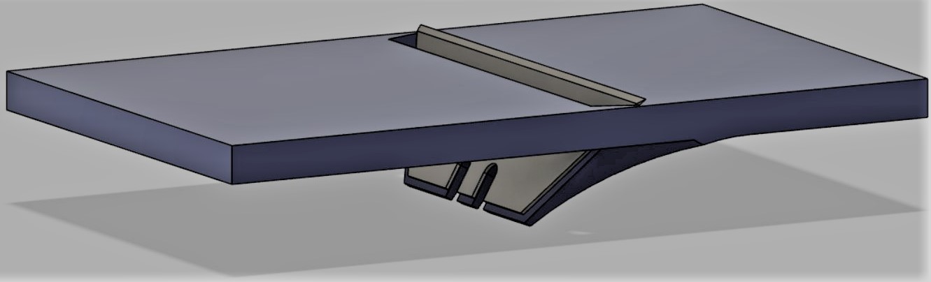
As usual with 3D models, I am using Fusion360, so I opened a new model and began with the razor blade. I chose to start with the razorblade as it's the only piece other than the motor that has a specific size. It's also the heart of the machine, as the blade is what is shaving the ice. Making the razor was a challenge in itself, as I could not figure out how to make the razor edge, as it's on two angles at once. I eventually settled on using a 3D sketch and the loft command. That's useful when making complex 3D shapes, the loft command can be powerful.

Once it was modeled I had to make the razor holder. I settled on having two razors that would be moving 10 cm back and forth. To hold the razor in place, I used the same sketch of the razor, but a bit bigger, and extruded that. It provides a flat surface on the same angle as the blade. I then made a rectangle to hold the two razors. It was 6 by 10 cm, 6 because the razor's edge is 6 cm long, and 10 because that's how much the razors will move, 5 cm to each direction. I then moved the flat surface down, combined it with the rectangular base, and extruded away a hole for the ice shaving to fall through and for the blade. I also added a large fillet to support the piece. Now I needed to copy and paste it to the back.
Before copying it though, I checked the blade in real life, and saw that the hole where I planned to put in some screws was too small. So I decided to make a hole for a nut, planning to drill a hole through the blade, then putting a screw in. So using Mcmaster carr, I used the built in feature, and got a standard M4 nut in. However, because of the fillet on the sides I could not get the octagon's shape. So I looked for the inner radius online, and made it myself. I then extruded a hole, making sure that it only cut the body I desired. One that was done, I had to make some 'legs' to hold the rods that act as rails and on which the Razor holder would slide on. I designed the legs, which were just a rectangle, an extrude, sketch a hole for the rod and extruded that. I am using a special plastic ring, that minimizes friction, so I made the hole slightly larger than my metal rods. But then I noticed that the rod would hit the Razor. So I extruded the sides of the rectangle and made it bigger. I also made a new component, ice, which would save the shape of the ice for future reference. Then I re-did the 'leg' and it worked this time. I made it a bit longer and mirrored it to the other two sides. Voila!
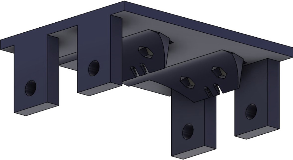
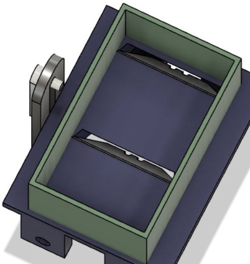
Next, I needed something to keep the ice in a fixed position. This was really simple, I just made a box and hollowed it out. That is a stationary part of the machine. I then started on the mechanism. I used a center to center slot to make the component that would turn, and then extruded it. On top of that component, I made two more circles, one to fit into the axle and the other for a pin. By the way, whenever printing, try making your holes a bit smaller than they should be, so that they can be press-fitted, this makes sure is stays inside. I then made two more center to center slots in another sketch, which is where the turning component's pin will go through. I extruded it, and pushed, so that it touches the Razorholder.
If you see it closely, you will see that the pin of the turning component would hit the razor holder so I made a small gap. I then connected the slot where the pin passes through part of the razorholder. Now that that was started, I needed something to hold my stationary part in green. So I designed some simple legs using some curves so that it would not hit the Razorholder and mirrored it over. That's when I realized that the stationary part is the perfect base, so I renamed it, and that would become the base of my mechanism.
I then went on a fillet rampage, and moved it a bit so it wouldn't hit the razors. I also noticed I had to make it much larger, because my Razorholder needs 5 cm on either side to slide. I cut the part and used the press pull command (which by the way should be tried whenever you are doing something similar to extrude or with a face, try it out, see if it works, and if not do something else it's a very veristile command) and glued the piece back together.
Now I need to make something to hold the rod, I used the 3D sketch feature so get the hole aligned. I extruded a simple, rectangle, made a hole, and then mirrored it over to the other side. I decided to have one side halfway filled, and make a cap, to that the rod does not fall out. So I extruded it back and had some simple holders.
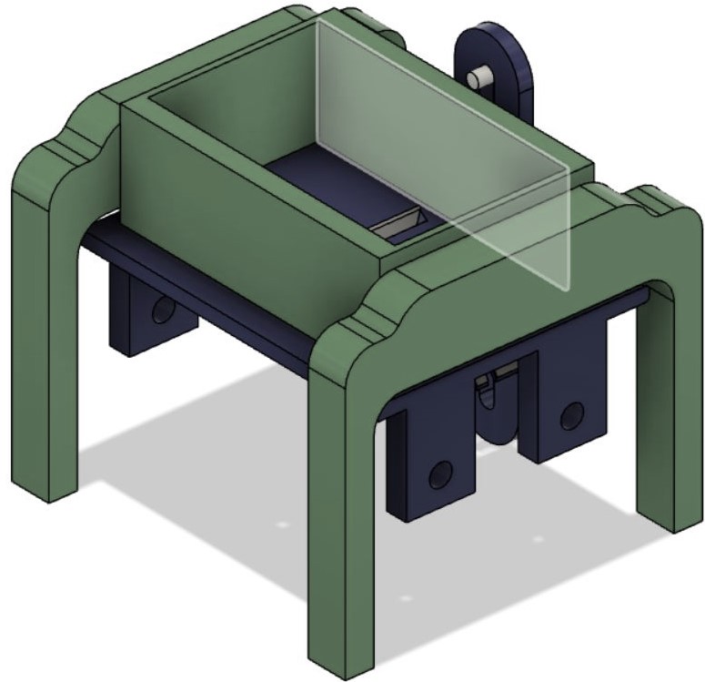
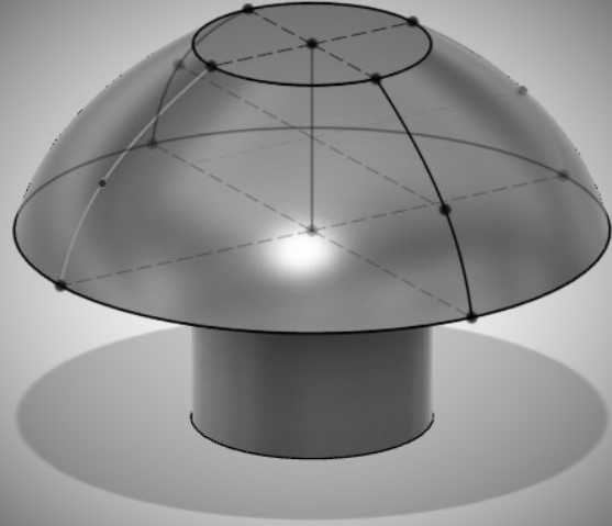
Now for the cap. I decided to make a mushroom shaped thing. Again a 3D sketch was my best freind, I made a circle, then a line up, another circle, and then another. I extruded the bottom circle for the 'stem' of the mushroom, and then using loft, connected the other two circles. However, it did not give the nice mushroom shape, so I made four guidlines which really used the different feutures of 3D sketching and then tried again. This time it worked nice and made a nice curve, so I made a component and then moved it to the base. Then I extruded the rods out and aligned them. Then I added some joints. I added a slider for the RazorHolder and a rotary one for the turningthing. When checking the joint and adding contrainsts, I found an issue, my rods were to short. So I cut my base again, moved it out, press pulled it together and joined it. Now I just need to add the electronic housing and a place for the motor!
To house the motor, I used the surface offset command along with the thicken command, and made a place that is slightly smaller than the motor so that it fits in snugly. I then revolved a rectangle out and extruded it at an angle until it met the motor housing. This looked cool and I gave it some fillets to round it off.
I then made a large box below to hold the electronics. I'm planning on using this thin plastic to keep the electronics safe, so I measured it, and then started a new sketch offset from the solid box. I made the sketch in the shape of the hole I wanted for the electronics, and extruded it untill the other face of the box. then I realized it cut into other parts of the body. So I split it up and extruded but this time only cutting the bodies I wished to cut.
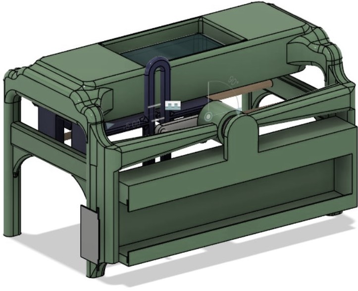
I then plugged the hole on the left, and used my standard fillets to smooth it off. Next I made two new sketches on the inside of the housing. I noticed that by battery holder had some holes in which one could push a piece through to hold it there with the power of friction. I drew those cylinders and made a slight inedentation in my back wall to align the battery and PCB perfectly. I also added some cylinders to hold my PCB. I then modeled the plastic piece to cover the electronics because why not!
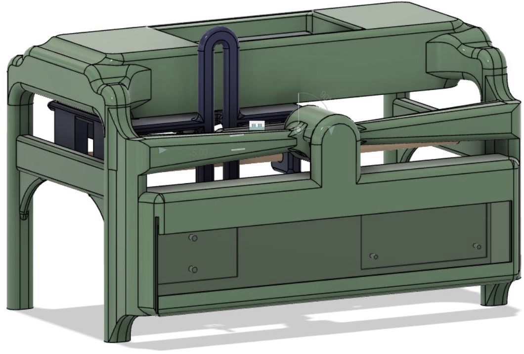
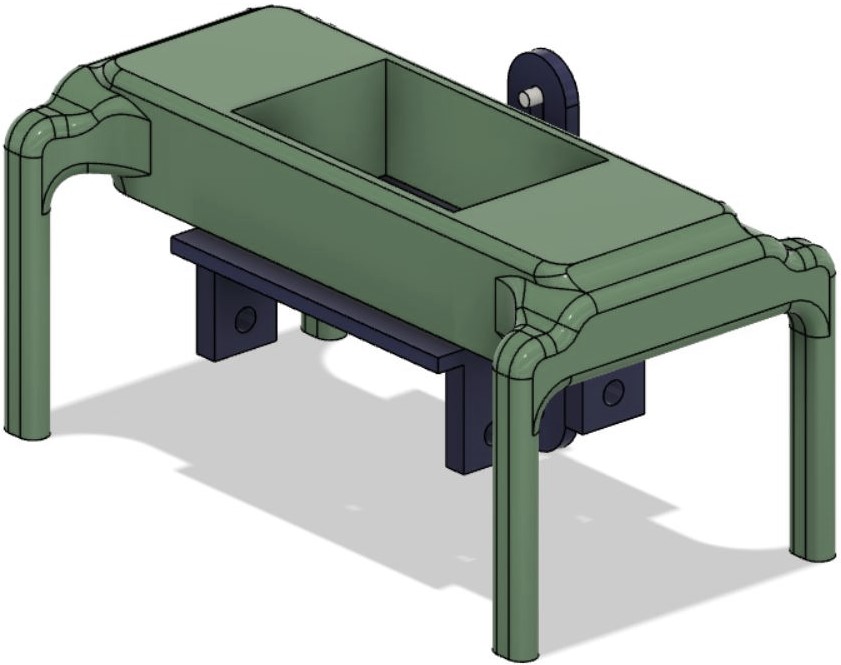
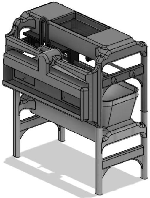
Next I started work on a similar part below the base which would catch the ice and funnel it into one area. This was really simple, using the timeline, I went back to when I had no housings, copied the base, and pasted it for later. Then, I extruded the legs up, and gave them a hole. This hole meets an extruded part on the base so that they fit together. Then I used the loft command to make a simple funnel, and moved it below the base. And voila, my model is complete!
Once the model was done, I exported it as an stl file, which can be read by Cura. To do this go to file, then click on export, and in the dropdown menu, select .stl as you file type. Then name it what you wish and click on export, choose a folder to save it in, and it's ready for Cura! I decided to export each piece individually as it gives me more control over the placement. So I exported each piece individually and oppened Cura.
Once in Cura, I decided that I would first print the Razor holder, the caps, the turning thingy, and the two rods. I opened moved them all into the right places, and changed the settings to what I did in the 3D printing week, and looked at the preview to make sure eveything it okay.
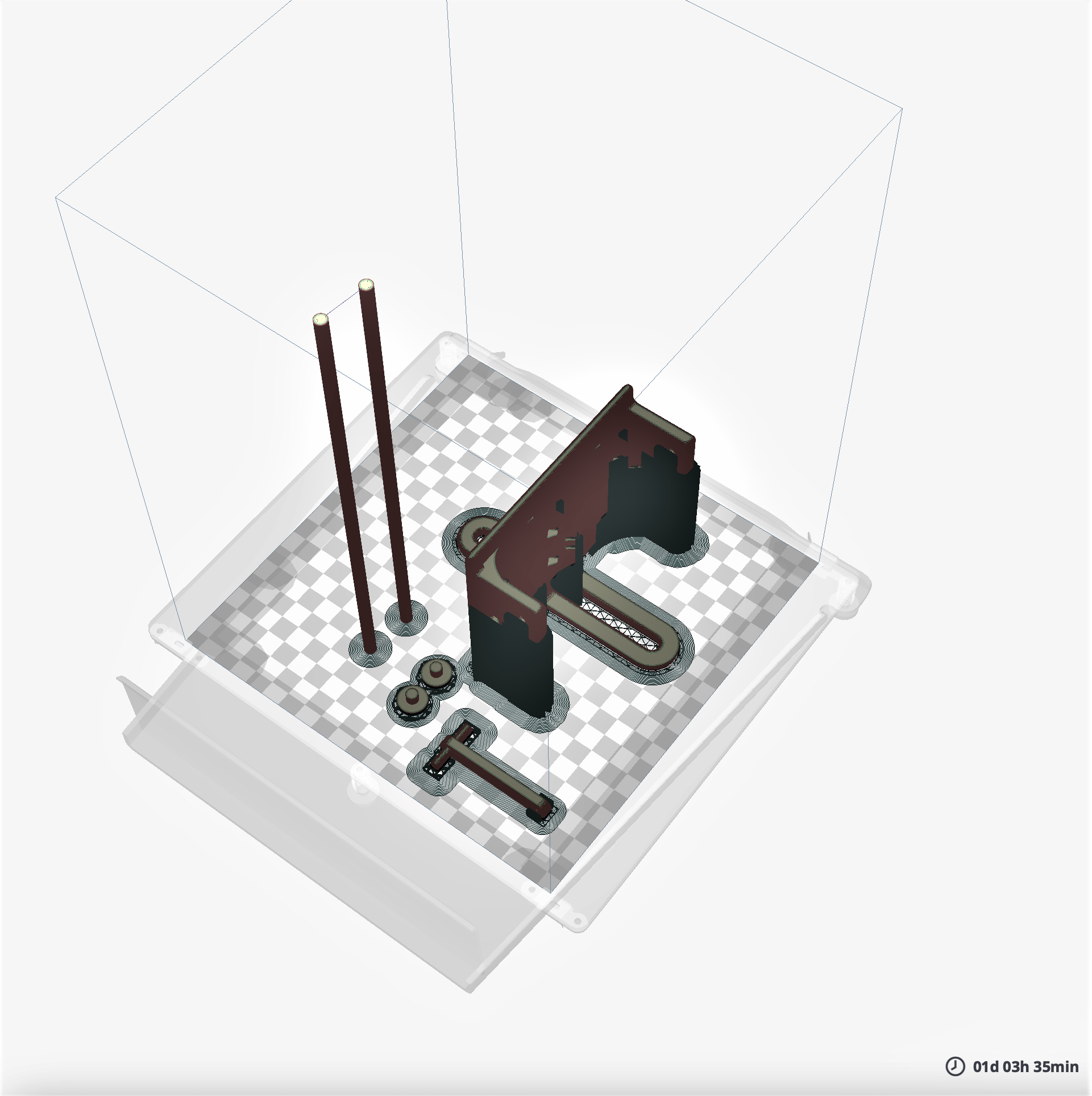
Then I hit go and let it run. Before leaving it on it's own, I checked it again and found that it failed. For some reason the supports got all tangled up and the bottom of the Razorholder's 'legs' So I had to try again. The setting were not to blame, but I increased the supports just in case.
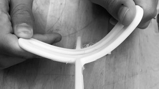
This next time, it did work, the RazorHolder printed succesfully! But the material was old and full of humidity. When I pulled it out, I could easily bend it, as if it were mere rubber! I had to reprint it in a stiffer PLA. But the rubber like properties could be useful for certain applications.
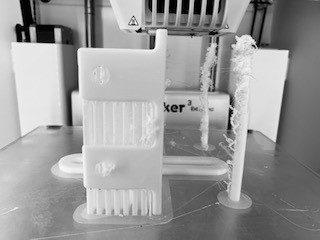
All the other pieces were fine as well, except for the rods, after a certain height they became a tangled mess. I think I need to add support next time, but it doesn't matter, as I was to use metal rods!
After a few tries, all parts printed successfully! Ready to assemble the machine!
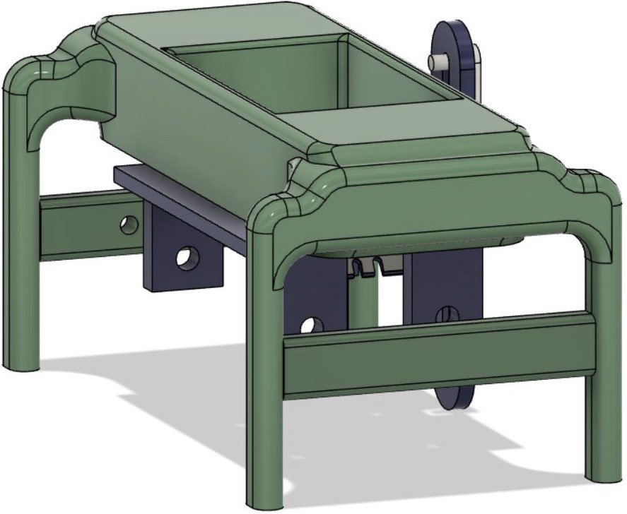
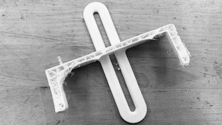
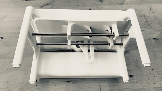
With all the parts printed I started to assemble the ice shaver machine. First, I mounted the razor blades into the razor blade holder. Then, I cut the rails to the appropriate length and after some filing of the frame, and integrating some linear bearings I checked for possible friction of the razor holder with the metal rails.
The razor blades edges were too long for the ice compartment, so I cut off the edges of the blades for a perfect fit. All the components came together nicely.
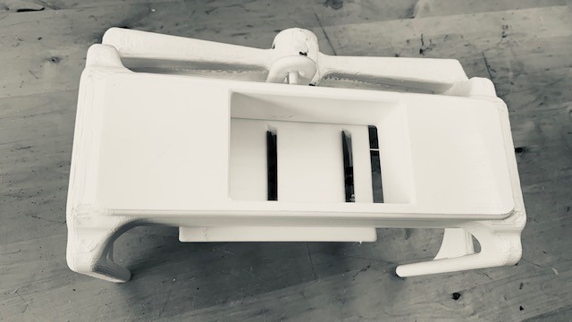
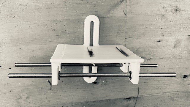
Viewing the ice shaver machine from the bottom you can see how all the components integrate.
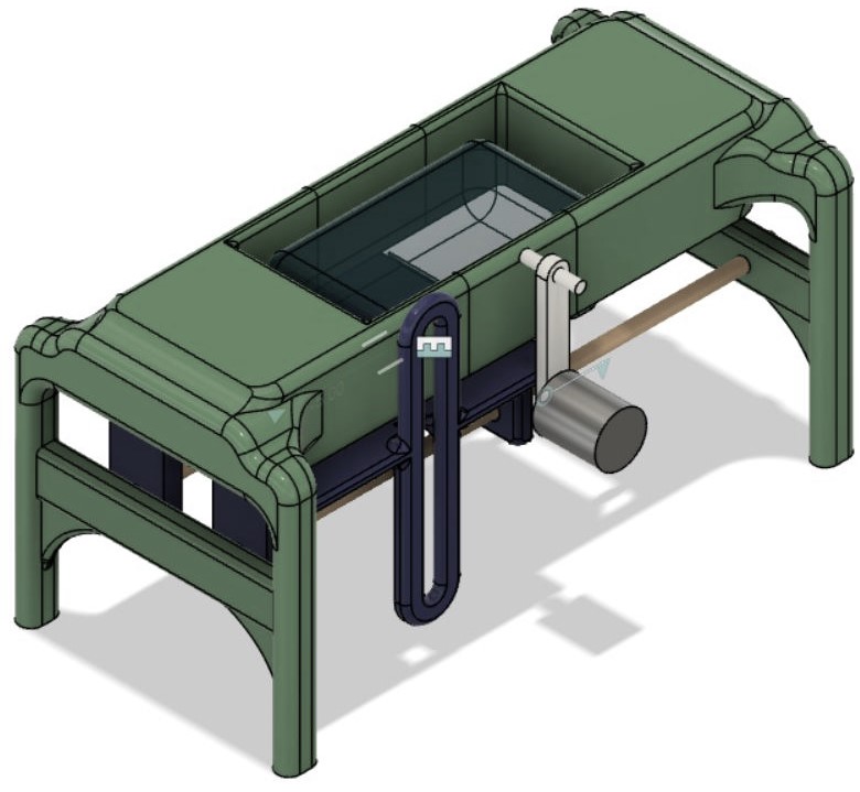
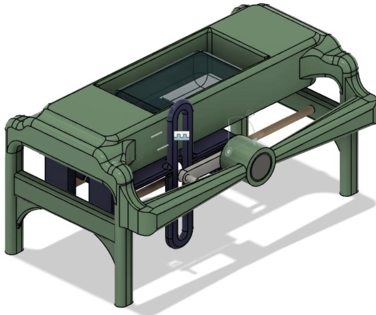
After the assembly of all components I tried to mechanically activate the ice shaver machine.
At first I was planning to just use a battery, a motor, and a switch as that would be cheap and easy and I had the parts. However, my regional mentor reminded me that I needed some actuation. Something intelligent had to happen. She also told me that I could use something commercial, which would save me from making my own PCB, but unfortunetaly, we don't have any commercial motor drivers, so I had to make my own... At the end, I didn't have enough time and resources to be able to incorporate the electronics this week. Nevertheless, I did try to automate the machine with a hobby motor but it stalled, not generating enough torque to be able to move all the parts. The plan is to complete the electronics portion in the output devices week, actuating a motor that could be integrated to the ice shaver project. Here is a link to that week.