4 - Electronics Production
I will make an in-circuit programmer by milling a PCB, solder all the components in place. Programm it and test it. With the group we will characterize the used machine and design rules for your PCB production process.
How can I use this in my final project?
Yes, a lot. My final project needs a:
- Microcontroller
- Wifi controller
- Heat pads (made of copper wire?)
- Power Adaptor 220 -> 5/3.3V (This I will buy)
Final files I created
The steps for this assignment
- How can I use this in my final project?
- Final files I created
- 1. Find the specifics of our milling machine
- 2. Create a PCB on the Milling machine
- 3. Solder the TinyMilly PCB
- 4. Program the PCB (ATTiny)
- program an other board (from electronics design week) with the ATTiny
- 5. Bonus: Make FTDI FT230X programmer
- Milling the FTDI FT230X
- Soldering the legs on the PCB
- Test the FTDI
- Hero shot FTDI:
- Mistakes I made & things to remember
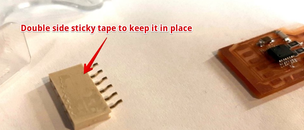
- Smart idea: Stick the connector with tape before soldering to hold it in place
- I soldered resistors on the place of LED’s on the ATTiny board
- I soldered the wrong value of transistors on the FTDI board
- Don’t use USB 3.0 for mac. Use a USB 2.0 hub
- Mistakes and lessons this week
- Wat went really good
- My concerns
1. Find the specifics of our milling machine
Characterize the design rules for your PCB production process. Our machine is a Roland Model MDX-20
All about the group assignment
2. Create a PCB on the Milling machine
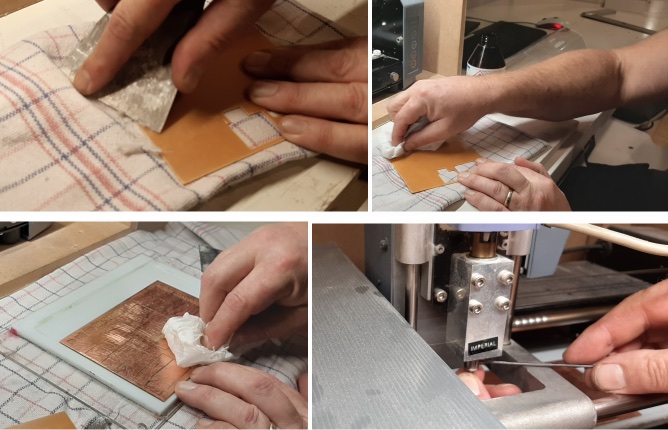
A. Prepare the copper plate
- Lay the copperplate on a towel
- Remove all sticky tape remains, use sticker remover
- Take ground plate out of the milling machine
- Remove all sticky tape from the ground plate
- Clean both plates, make sure both plates will be completely flat
- Apply sticky tape on the part you are going to mill AND around make sure the plate doesn’t move
- You can use a ‘knock-test to hear if all is fully attached
- Attach the ground plate (gently tightening the screws)
- Power (green button) on the Milling machine
- The machine should be in ‘View’ mode (plate to the front, miller y pos = top)
B. Mod settings on computer & Drill insertion
- Start Server.sh (link on desktop)
- Click Run in terminal in dialog (you will see the terminal now & the browser)
- Right-click in Mods
- Programs > Open Program > Roland MDX-20 > PCB
- MOD: Read PNG >Open PNG
- Check the size
- Change the DPI
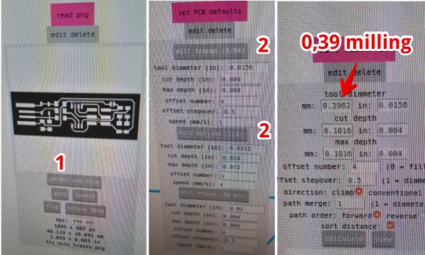
- Mod: Default Settings -> Mill traces/Mill outline
- Mod: Mill Raster 2D
- Tool diameter 0.39,
- Cut dept 0.08 & Max Dept 0.08
- Offset number: 4 cleared distance around traces
- Direction: Climb
- Click ‘Calulate’ - mod: View toolpad > View
- Roland MDX milling machine
- Speed: 1 (traces) / Outline ∑: 4
- Speed: 1 (traces) / Outline ∑: 4
C. Place the miller
- Set the head in middle position
- Hold the mill with two fingers (prevent mill from dropping)
- Loosen the two hexagon socket screws


D. Set starting point (x-y)
The starting point is on the left lower corner.
- press ‘View’ till head beth moves to the back (head is on the left)
- On MDX-20 mill > Lower the head completely Down key
- Mod: Rolands MCX-20 Milling -> Use x and y to set the origin (lower left corner)
- ‘UP’ on machine (click one time)
- Lower the mill (let it rest on the copper) and tighten the hex screws
- Check if the miller rotates, by turning the head by hand

- mod: Mill Raster 2D -> Calculate
- mod: Websocket Python serial
- Select RTSCTS
- Close socket/ open socket
- Close port / open port (see if this is visible in terminal)
- Send File
Mill outline shortlist The outline (border of black & White) wil be cut. It will cut black side of the border.
- Select PNG
- Set defaults to outline
- Change mill
- Set speed to 4
Reset the milling machine (when you want to cancel a job)
- On Milling Machine:
- Press View
- Hold UP & DOWN
- View led starts blinking
- On MoDs (Websocket Python)
- Cancel
- Close port
- Close Close Socket
- Mod Mill Raster 2D:
- Calculate
3. Solder the TinyMilly PCB
You need:
- Pliers
- Soldering station with a thin soldering tip and a wet sponge
- a good magnifier lamp
- A piece of paper (A5) & Double Sided Tape
Steps:
- Wash the board with soap (remove oil from your fingers)
- Stick your circuit board on paper to make handling much easier.
- Draw the components on the paper
- Use a soldering temperature of 350ºC to 370ºC (De Waag uses ºF)
- Put little solder on one of the legs of your component
- Solder this leg to the board
- Solder the other leg(s)
First Sign of life. LED is ON 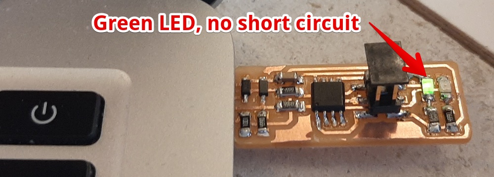
Hero Shot ATTiny
Lessons learned
I used the wrong components
solution: make a drawing. So you can look at the paper, not at the computer 
I had troubles finding the GND on led and Diode
So I looked it up:
Soldering was too hard
I started soldering with 340ºC, but is was really hard. I found in this forum post the temperature for SMD should be between 350 & 370ºC. To be on the save side I used 360 for my first PCB (the ATtiny board). 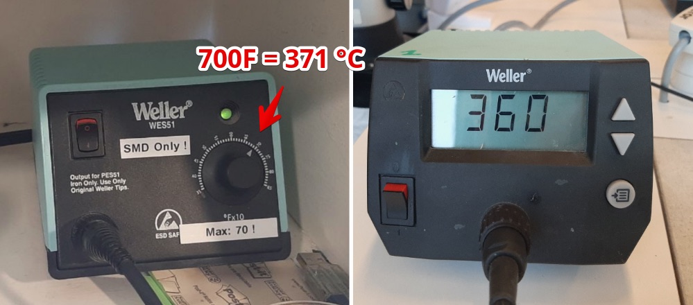
At De Waag the stations are set to 370ºC(700ºF) this was even better to solder the really tiny components. I used this for my FTDI board.
4. Program the PCB (ATTiny)
This steps will program my Tiny using another board (the programmer)
b. Setting up the IDE - happy flow
- Download and install CrossPack. (I used CrossPack-AVR-20131216.dmg)
- Allow CrossPack to run (see images below)
- Download the firmware
- Unzip, and put unzipped files in a folder (in my case /Users/harmvanvugt/fabAcademy/Tiny/)
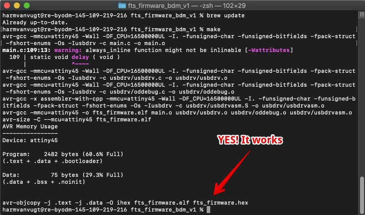
- In Terminal. Go to the folder and execute one by one
$ brew install avrdude
$ brew tap osx-cross/avr
$ brew install avr-gcc
$ brew search avr
$ brew update
$ make
When you see this, you can go to the next step
What went wrong and how I solved it
Error CrossPack cannot be opened
This resulted in an error (see below) - give access to CrossPack via ‘Security & Privacy’ 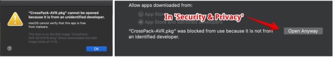
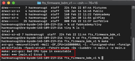
“make” resulted in a error
make: avr-gcc: Bad CPU type in executable
When looking for solutions I found the Fab Academy website of Woma.
Butt “brew install avr-libc” gave an error. Looking for a solution this github page suggested I use “brew tap osx-cross/avr && brew install avr-gcc” (see error below)
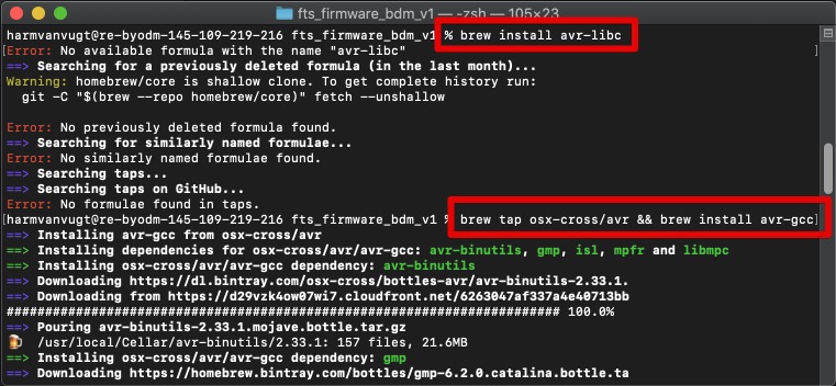 Solution. Use ‘brew install avr-gcc’
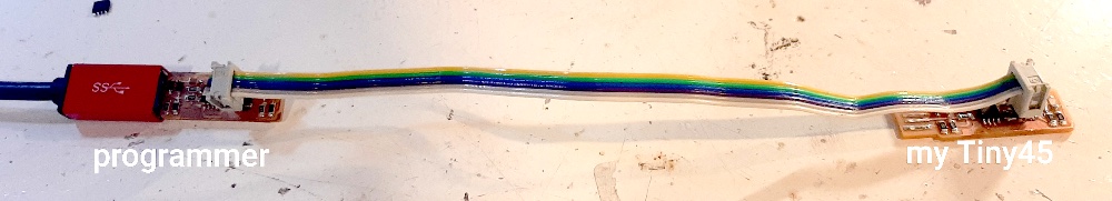
c. Program my Tiny board using a programmer (another Tiny?)
Plug the programmer board in the USB and connect to my Tiny USB2.0 -> Programmer board -> myTiny
Run make flash. will erase the target chip, and program its flash memory with the contents of the .hex file you built before. 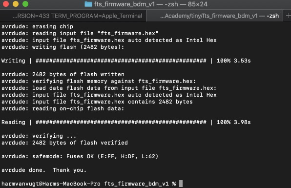
Run make fuses Sets the configuration fuses 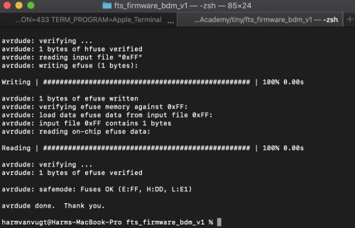
Now be really careful! Don’t blow the fuses before this check.
- Plug your Tiny in your USB 2.0
- Go to apple > About this mac > System Report > USB
- Is your USBtinyISP visible (see below)? Go to the next step.
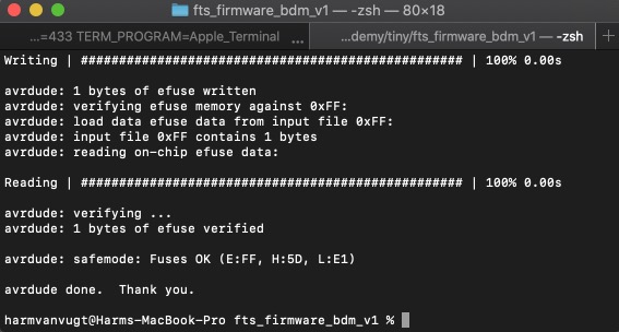
Blow fuses
- Connect Your Tiny via an Programmer again
- Run make rstdisbl in terminal. The result should be:
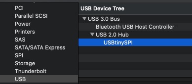
Check if your board is an ISP
- Plug your Tiny into your USB port
- apple > About this mac > System Report > USB
- Is your board visible? You made it!!! (see image below)
program an other board (from electronics design week) with the ATTiny
And read the serial data via the FTDI

I followed this instruction to programm the Attiny 44
These are the settings: 
Setup: 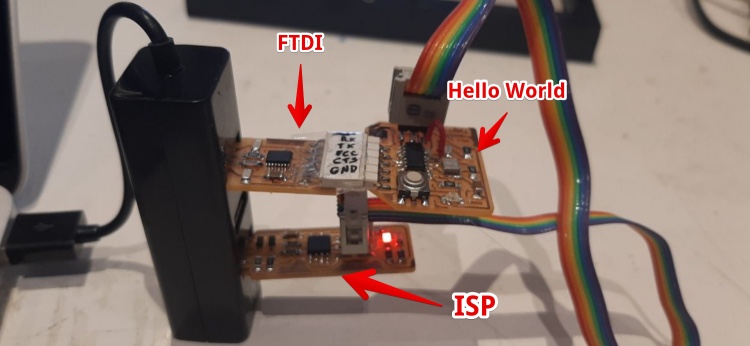
code:
#include <SoftwareSerial.h>

SoftwareSerial mySerial(2, 1); // RX, TX

void setup()
{

  // set the data rate for the SoftwareSerial port
  mySerial.begin(9600);
  }


void loop() // run over and over

{
int thing = analogRead (2);
  mySerial.println(thing);
  delay(100);

}
Hero shot, showing me uploading the code using the ISP and getting serial data (analog value Thermistor) back from the Hello world board:
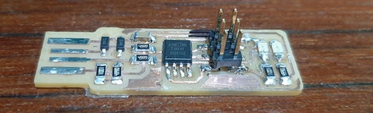
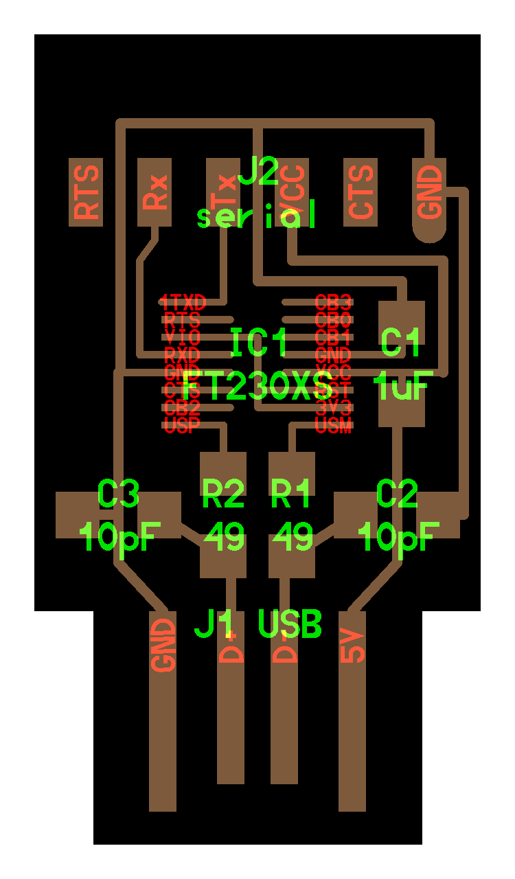
5. Bonus: Make FTDI FT230X programmer
Since I was ready creating the ATTiny programmer we started with a more advanced programmer. The FT230X. We got the PNG’s from the FabAcacemy Page search for ‘FTDI’ to jump to the right section.
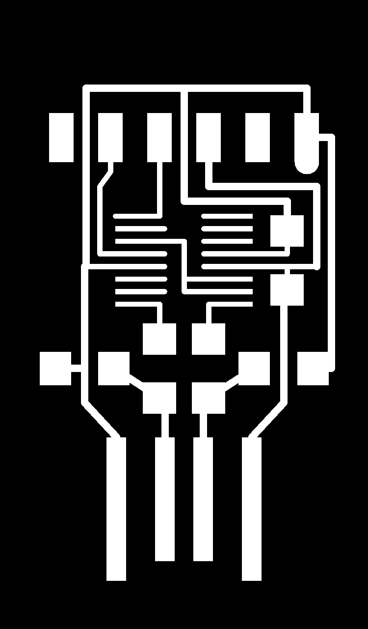
Milling the FTDI FT230X
Milling the board went really well, I used my steps for milling in chapter 2. This board took 40 minutes to mill. Together with getting the plate ready the board came out within 1 hour. Files (via the academy) page:
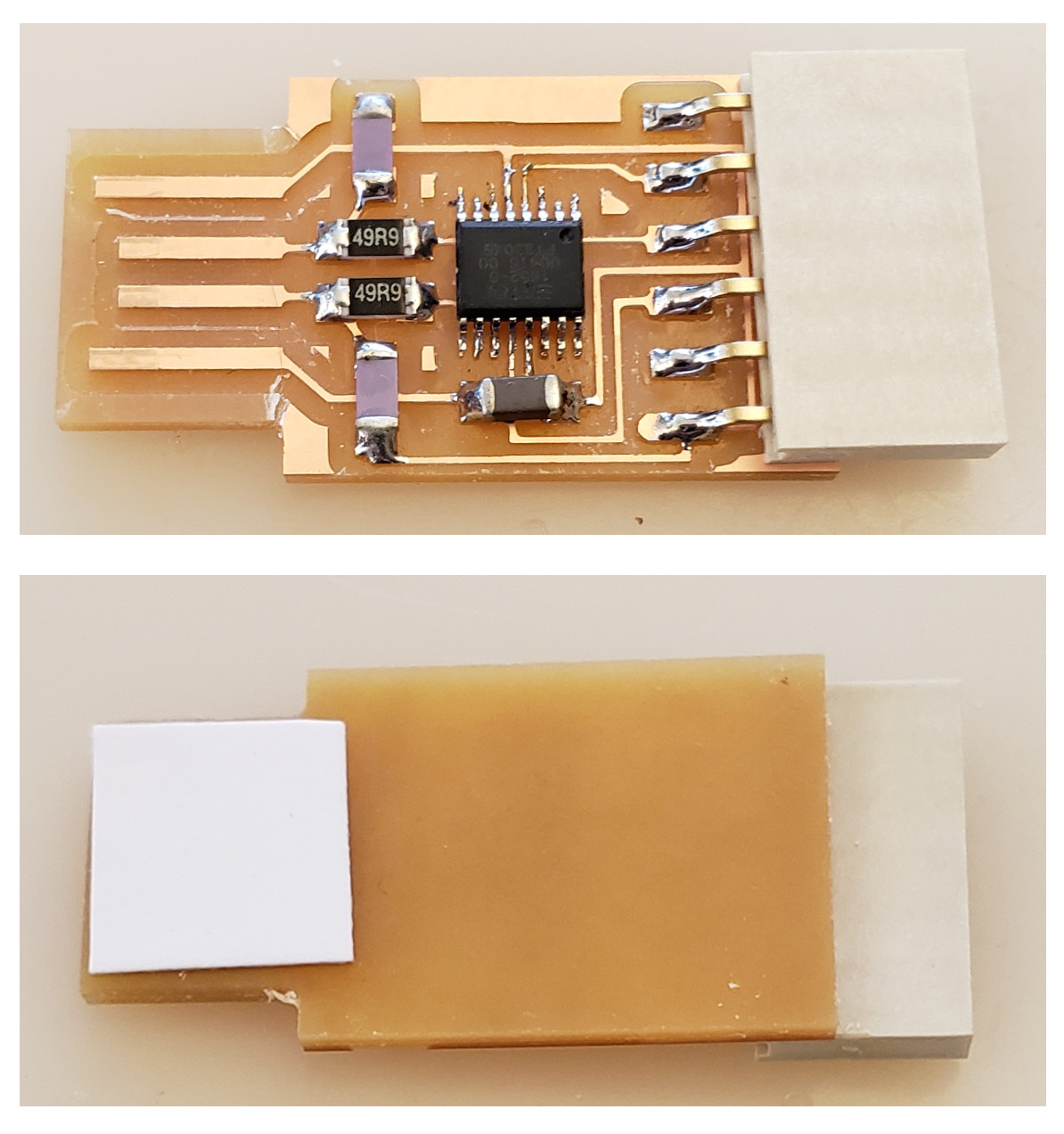
Soldering the legs on the PCB
- Put a tiny bit of solder on one of corners where the FT230x should be
- Fix the chip and solder the opposite corner
- Now solder the other legs, I tried not to solder all legs together. And managed (almost)
- Two legs stuck together and Henk helped me to get the solder out using his amzing electric vacuum desoldering pump.
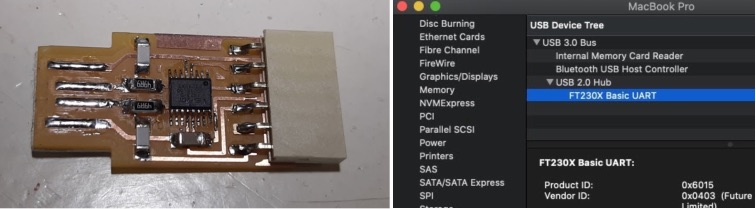
Test the FTDI
- Install the drivers https://www.ftdichip.com/Drivers/VCP.htm
- Insert the FTDI in the USB 2.0 port (for mac you need a HUB)
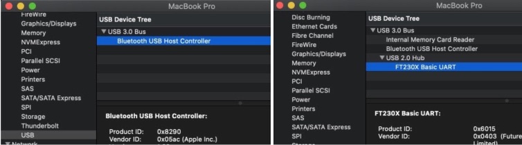
- Open mac > About this mac > USB, If all worked you will see the ‘FT230X Basic UART’
Hero shot FTDI:
Mistakes I made & things to remember
Smart idea: Stick the connector with tape before soldering to hold it in place
I soldered resistors on the place of LED’s on the ATTiny board
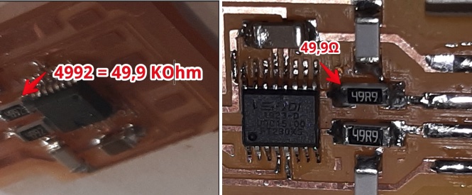
I soldered the wrong value of transistors on the FTDI board
So always double check the components before soldering them. If Resistors, use this table resistor values
Don’t use USB 3.0 for mac. Use a USB 2.0 hub
Mistakes and lessons this week
- Triple check the components (type and value) before soldering
Wat went really good
- The soldering was really fun
My concerns
- This is hard, my final project will have a lot of electronics can I make this in just 2 weeks?