15. Networking and Communications
This week I worked on defining my final project idea and started to getting used to the documentation process.
Group Class
Simplicity is the key
Don’t make it unnecessary complicated
A logic analyzer is an electronic instrument that captures and displays multiple signals from a digital system or digital circuit. A logic analyzer may convert the captured data into timing diagrams, protocol decodes, state machine traces, assembly language, or may correlate assembly with source-level software.
-costs almost 5 dollars and does the useful job
You have to invent your own Protocol
RX reciever TX transmitter
Individual Assignment¶¶
Files to download
HC-05 Bluetooth module
Im planning to use HC-05 which has two operating modes, one is the Data mode in which it can send and receive data from other Bluetooth devices and the other is the AT Command mode where the default device settings can be changed(so works as master and slave)
Below you can see the Data sheet for it - for more technical properties HC-05 Data sheet
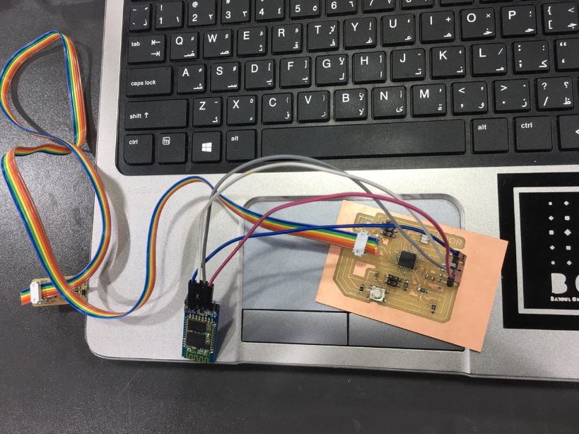
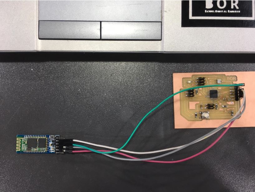
The HC-05 module easily paired with microcontrollers because it operates using the Serial Port Protocol (SPP). Simply power the module with +5V and connect the Rx pin of the module to the Tx of MCU and Tx pin of module to Rx of MCU.
During power up the key pin can be grounded to enter into Command mode, if left free it will by default enter into the data mode.
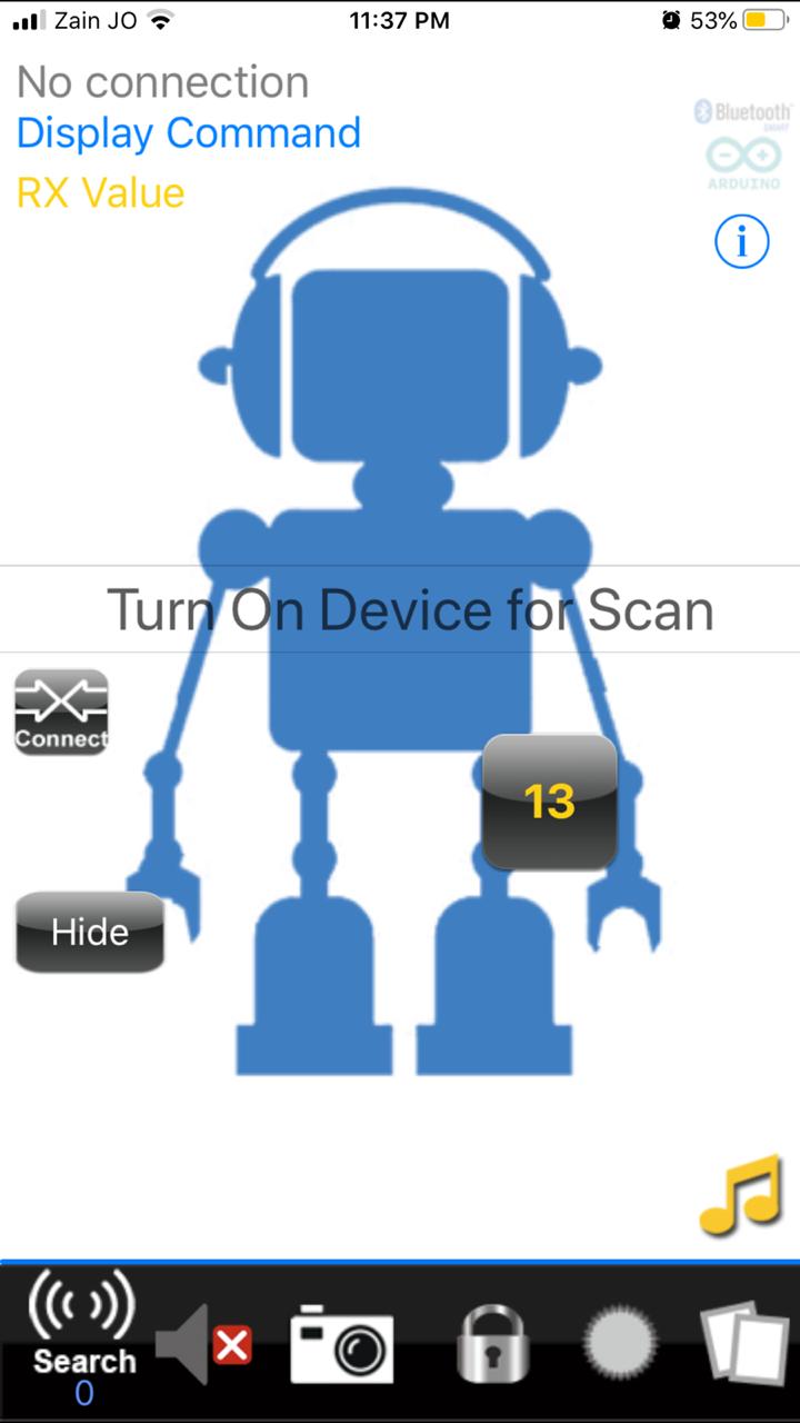
As soon as the module is powered you should be able to discover the Bluetooth device as “HC-05” then connect with it using the default password 1234 and start communicating with it.
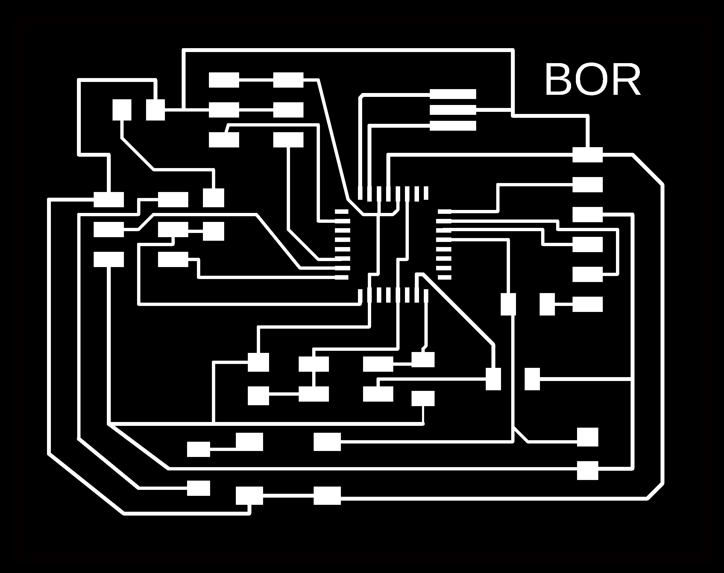

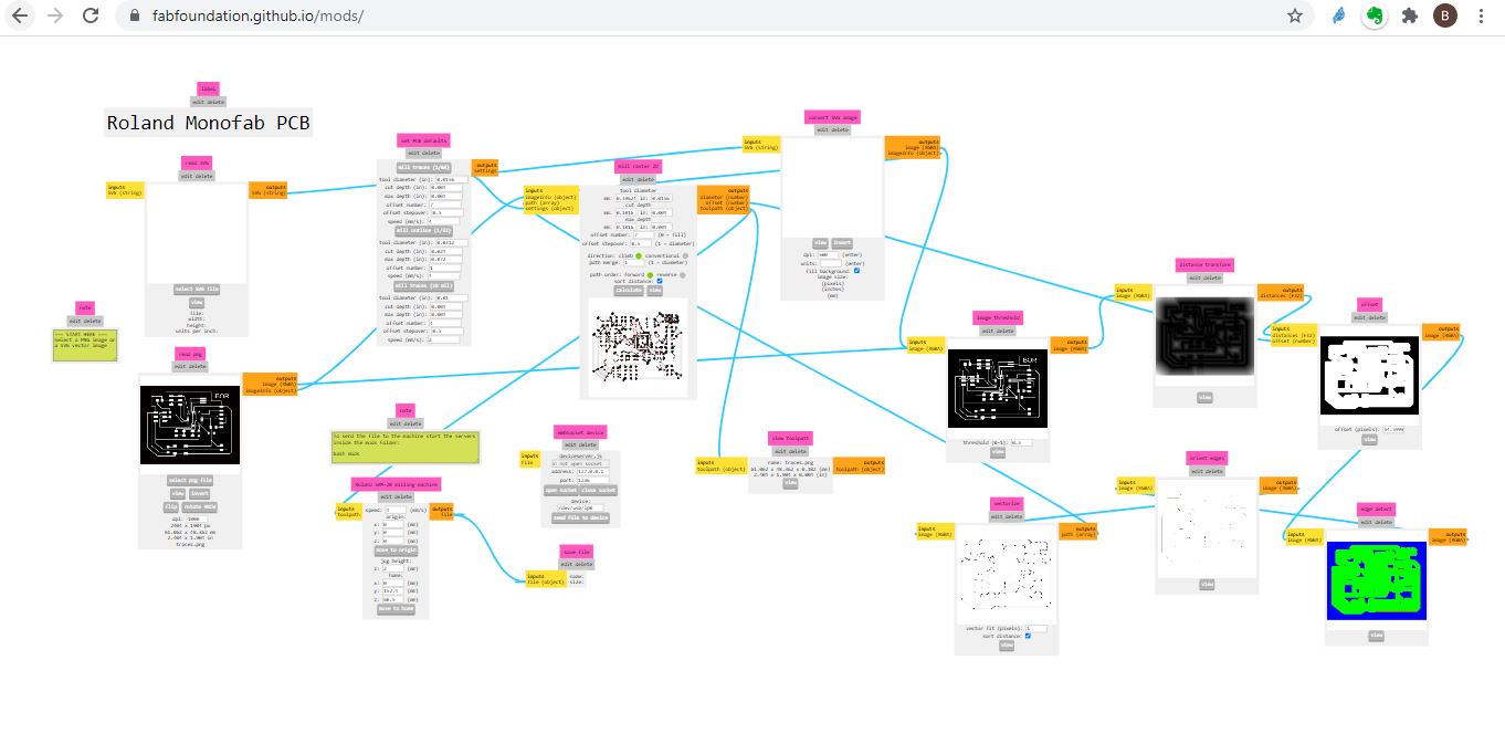
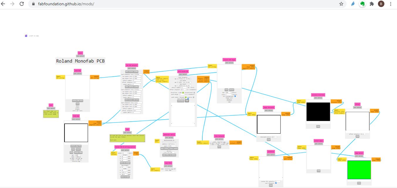
That i used later on mods to cut my via Rolan Monofab PCB machine
i used arduino to program my board after i downladed the need libraries for windows check week 9 for specific details
Code
#define ledPin 17
int state = 0;
void setup() {
  pinMode(ledPin, OUTPUT);
  digitalWrite(ledPin, LOW);
  Serial.begin(38400); // Default communication rate of the Bluetooth module
}
void loop() {
  if(Serial.available() > 0){ // Checks whether data is comming from the serial port
    state = Serial.read(); // Reads the data from the serial port
 }
 if (state == '0') {
  digitalWrite(ledPin, LOW); // Turn LED OFF
  Serial.println("LED: OFF"); // Send back, to the phone, the String "LED: ON"
  state = 0;
 }
 else if (state == '1') {
  digitalWrite(ledPin, HIGH);
  Serial.println("LED: ON");;
  state = 0;
 }
}
Board used
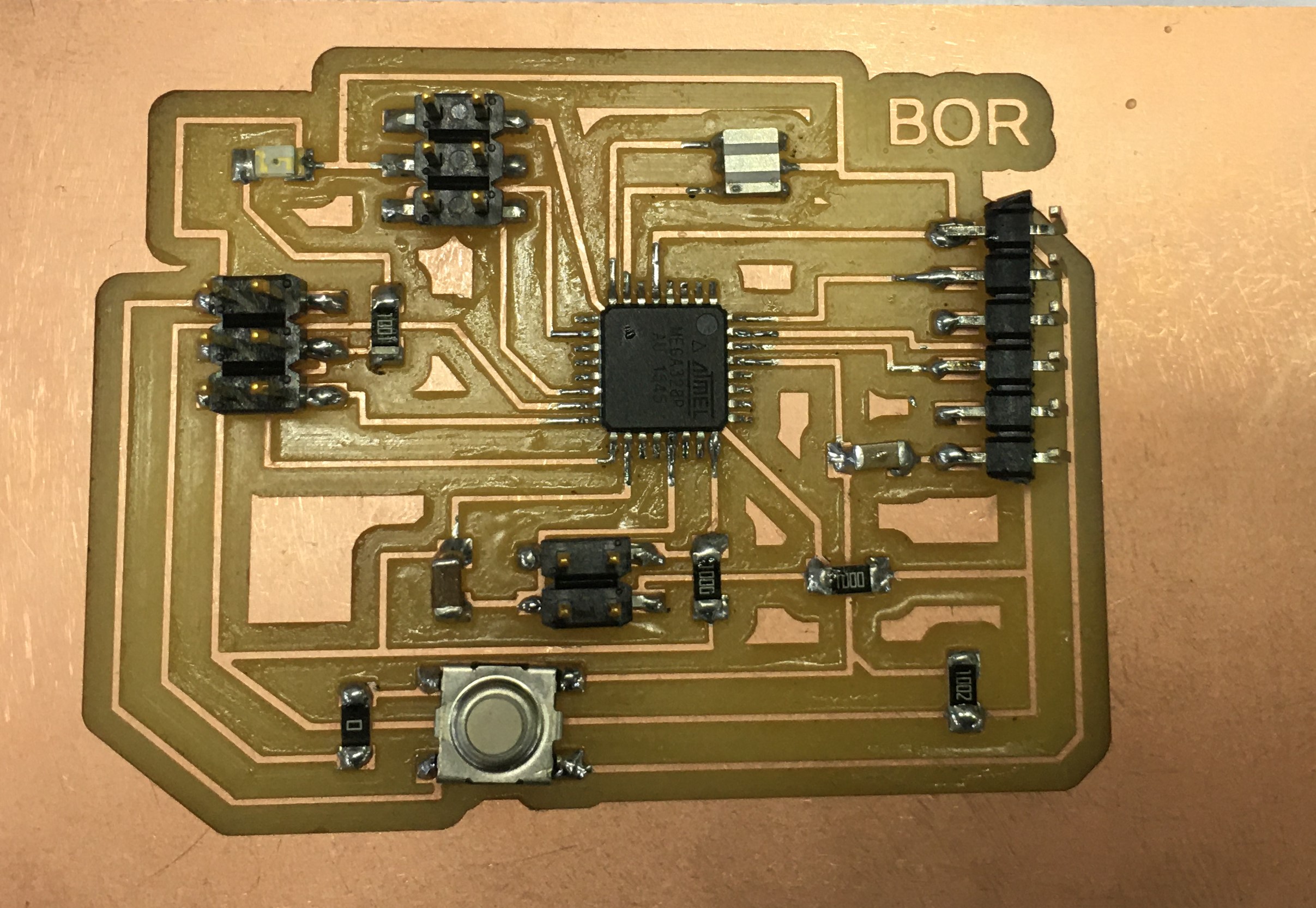
I am gonna use the output board instead of the FTDI… ill see which pin from that component i would use for the Bluetooth …
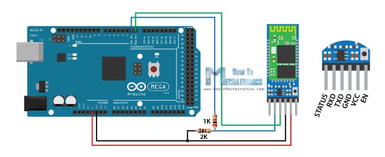
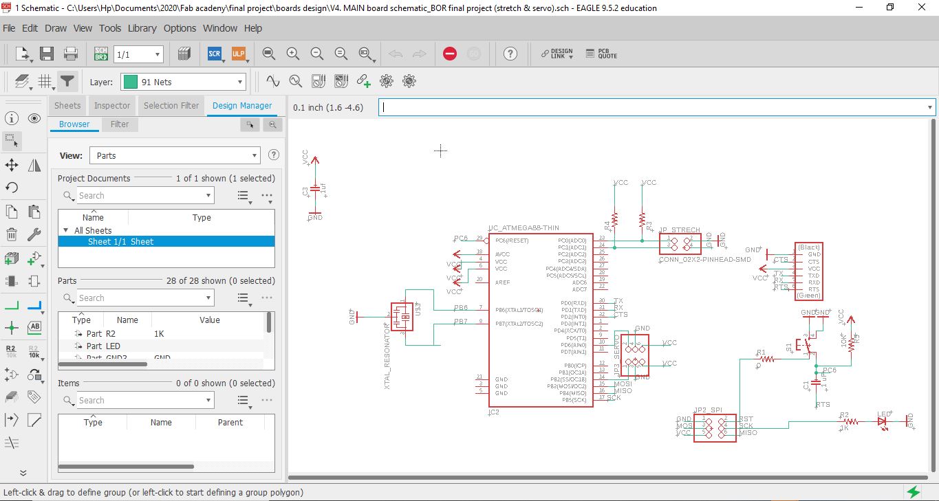
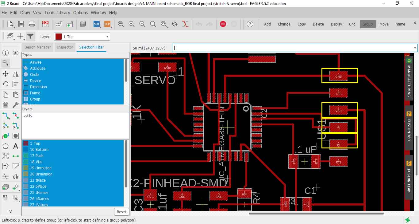
so i followed these pins to connect my board to the Bluetooth based on this schematic

Hero Shot