7. Electronics design
This week I worked on defining my final project idea and started to getting used to the documentation process.
Files to download
Research
R1 = Resistor C1 = Capacitor VCC = voltage (+ve black) GND = Ground (-ve red)
Useful links
Basics
Ohm’s Law = 1-Voltage (V)(as if pressure) 2-Currrent (I) 3-Resistor (R) V= I * R
IC1= Microprocessor
Kind reminder
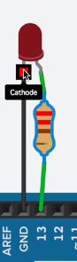
The positive leg of the LED called Anode - usually have a longer leg
(and is wired to power)
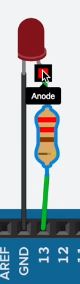
The Negative leg of the LED called Cathode - usually have a shorter leg
(connects to ground)
Group Project
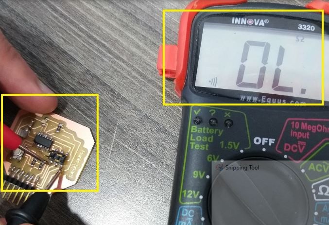
Using the digital multimeter to check the continuity between ground pins and VCC pins. Also, we measured the VCC to GND voltage, which should be 5V.
GND (Ground) Continuity-
We measured the continuity between the GND pins of the ATtiny44, SPI header and FTDI header. The digital multimeter should beep and read around 0 Ohm. This means all the three pins are connected.
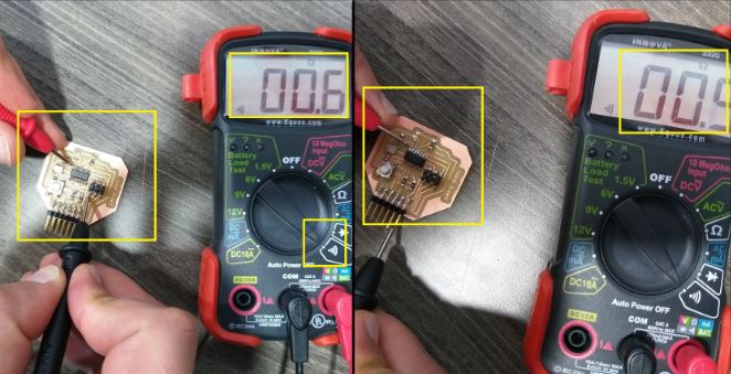
VCC (5V) Continuity-
We measured the continuity between the VCC pins of the ATtiny44, SPI header and FTDI header. The digital multimeter should beep and read around 0 Ohm. This means all the three pins are connected.
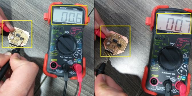
VCC-GND Continuity-
We measured the continuity between the VCC pin and GND pin. The digital multimeter should not beep and read OL (Overload). This means there is no connection (short circuit) between the VCC and GND.
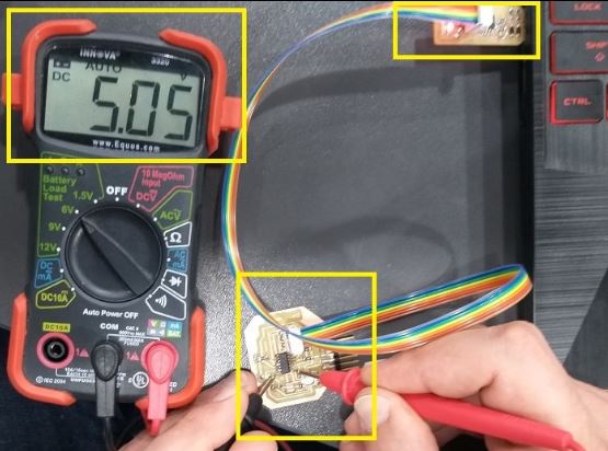
VCC to GND Voltage
We connected the board to the FabTiny programmer and then to USB. We measured the voltage between the VCC pin and GND pin. The digital multimeter read 5V, which is the USB port voltage.
Individual Assignments
KiCad
Download - KiCad
resonator and capacitor make them close to their connections
layer on the right side (like layers on Autocad) F.Silks check and uncheck to display the name or hide them (making it easier to see)
Design rules -Width (thickness of the line/traces if too thin might rup off while cutting) -Clearance (offset how much it removes from copper - the minimum would be the size of bit/milling if this distance was less than diameter of the bit then game over it won’t see it or cut it and cooper would remain there between 2 traces as if it’s one line or trace )
- F.Cu
- Ege.Cuts the only 2 layers i need to keep before exporting
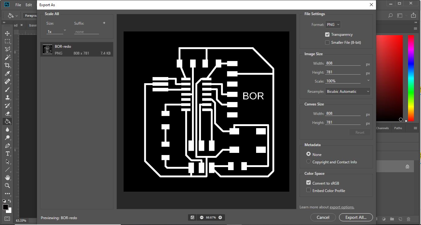
then open on photoshop open with a high resolution 500 then export PNG or SVG (takes both)
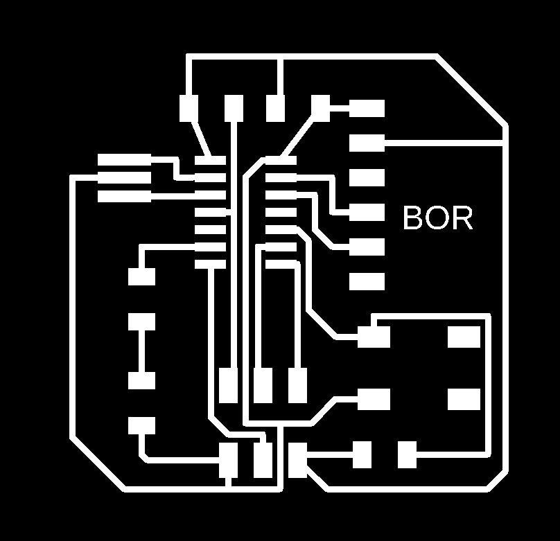
then for interior you make everything white export SVG file
Multi meter my new best friend during electronics
Eagle
Step 1 download Eagle - Eagle
Step 2 Download the PNG of the board to follow - ATtiny44 Board
Step 3 download LBR/ BRU (in schematic) in library update (to add it)
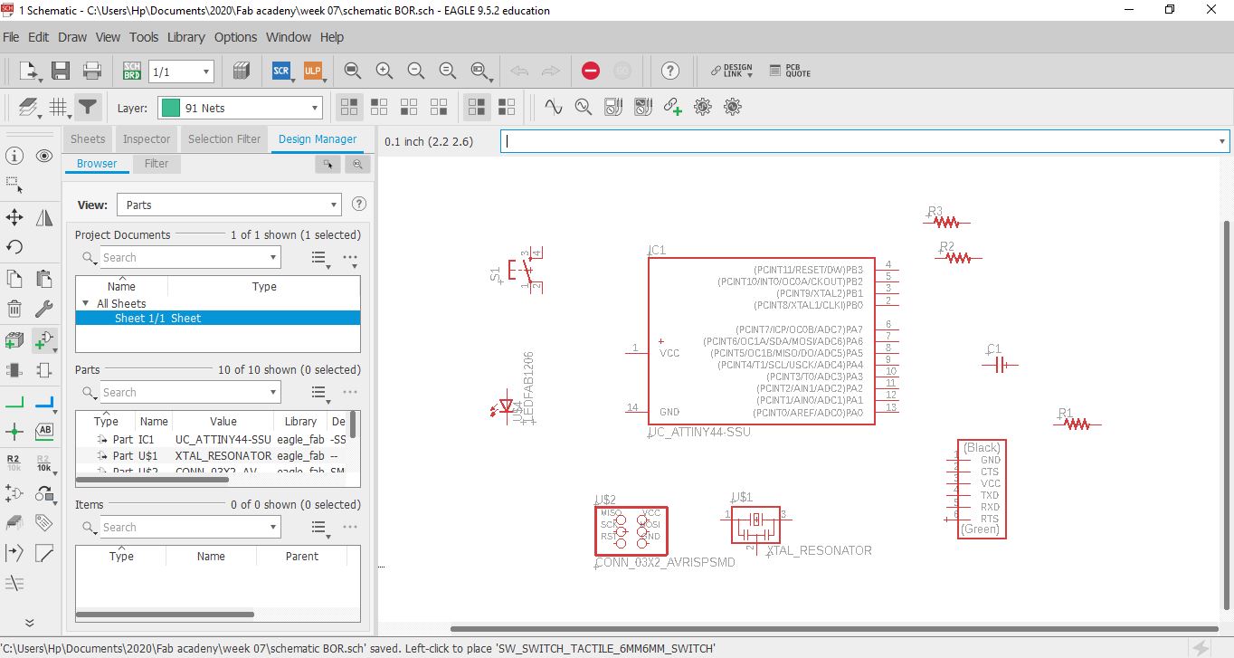
Step 4 Right click on your project and select “New > Schematic”. This will add a schematic to your project and open the “Schematic Editor”. (in schematic) Add components- originals * add to schematic the components of the original echo hello-world board. Click on “Add Part” and in search field look for “tiny“. Double click on “UC_ATTINY44” under fab library. Select “UC_ATTINY44 - SOIC14” and click “OK”. repeat for all these basic components in the table below * you can connect visually by line or simply label9 and rename then they would connect automatically and it would ask you with a popup menu if you wanna connect and you put yes)
Step 5
(in schematic) Add LED +Res.+switch + Bottom as in table below.
schematic should look similar to the image below. You can arrange components in schematic as your preference.
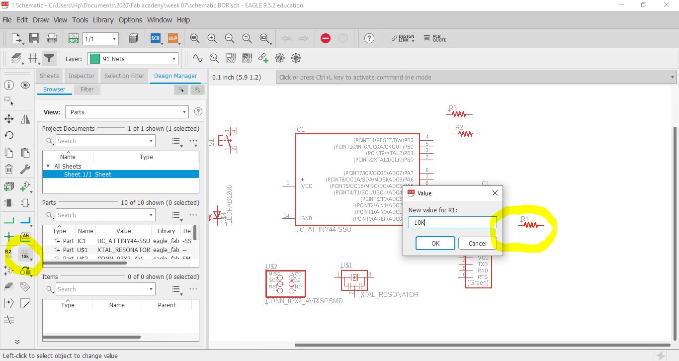
step 6
change value of Resistor
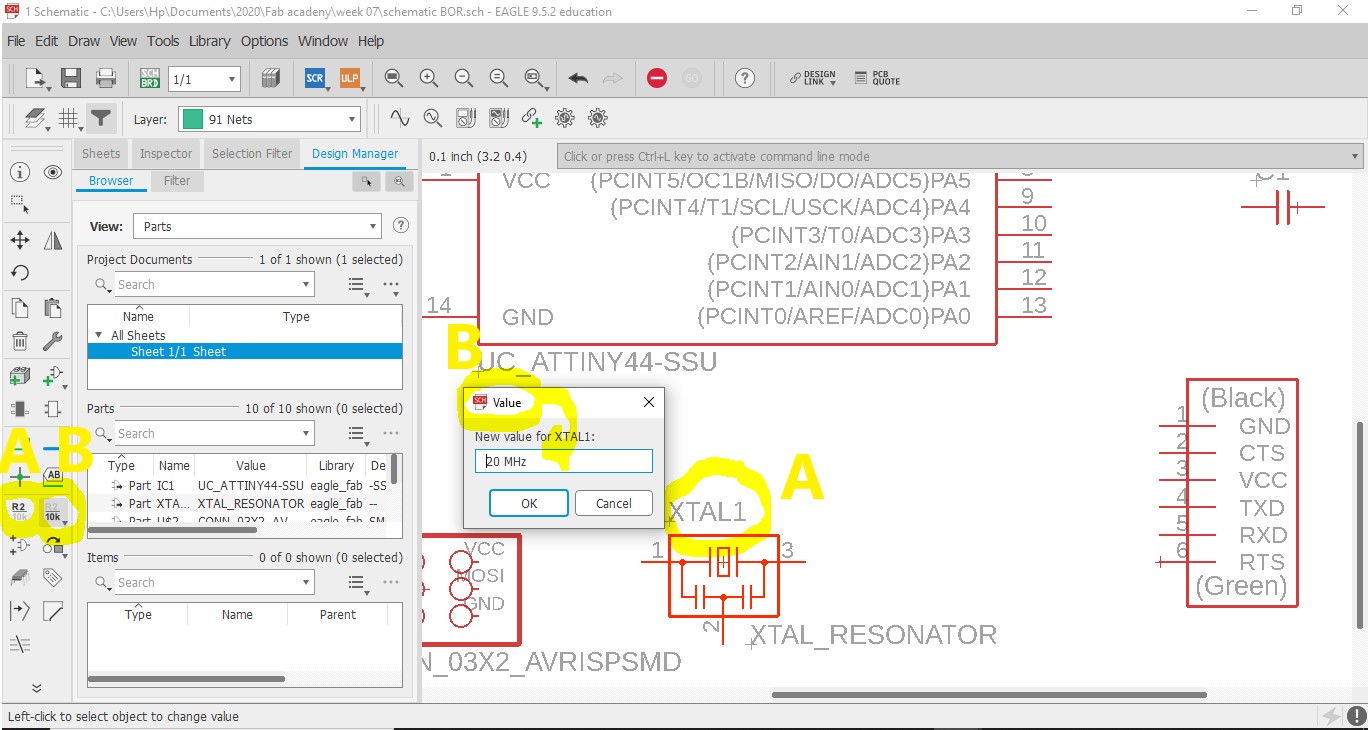
step 7
Change name and value of Resonator
step 8 Add VCC and GND - make each connection needed to them as the diagram
Step 9
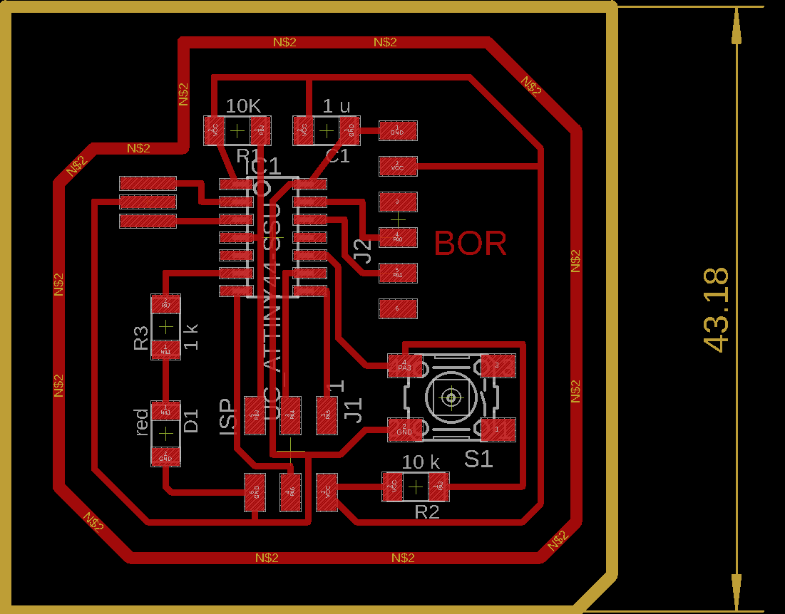
Go to board and connect components
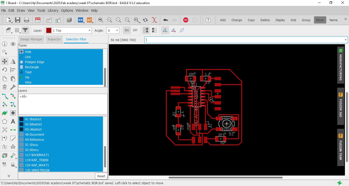
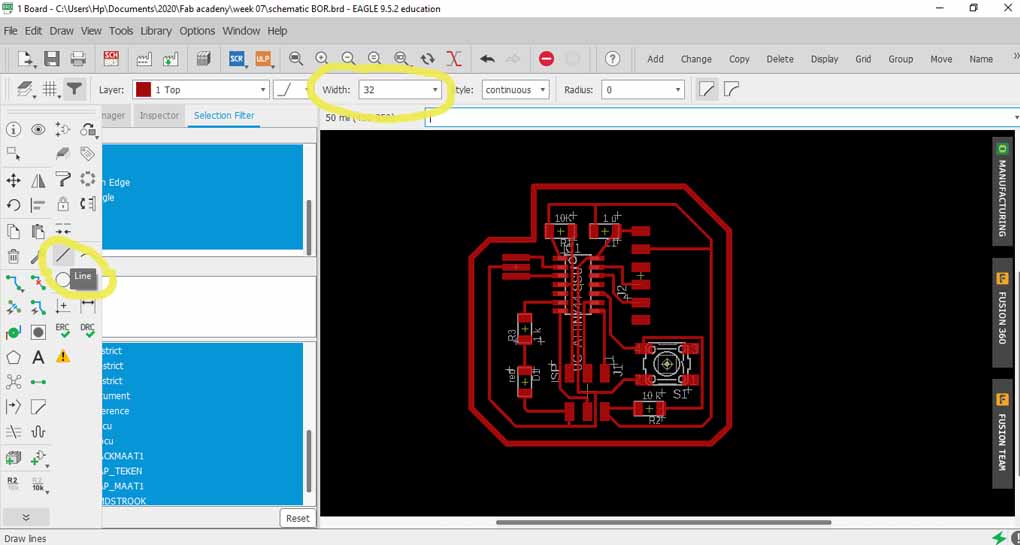
Step 10
Draw outline with 32 thickness (anything higher than traces) of the line
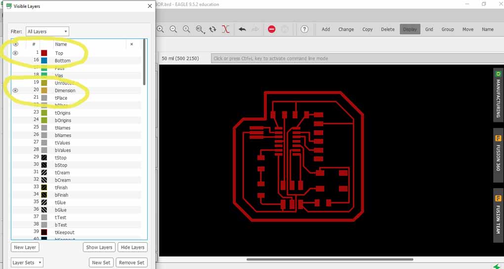
step 11
In order to export the traces and interiors as png files, so we can use in mods to generate the rml files for the milling machine. Go to “Layer Settings” and hide all layers by clicking on the eye icon, only keep “1 Top” and “20 Dimension”. Click “OK”.
Step 12
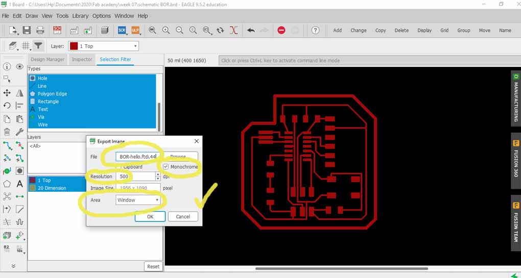
Export Image(Resolution 500) - monochromic
and please give your file a name!
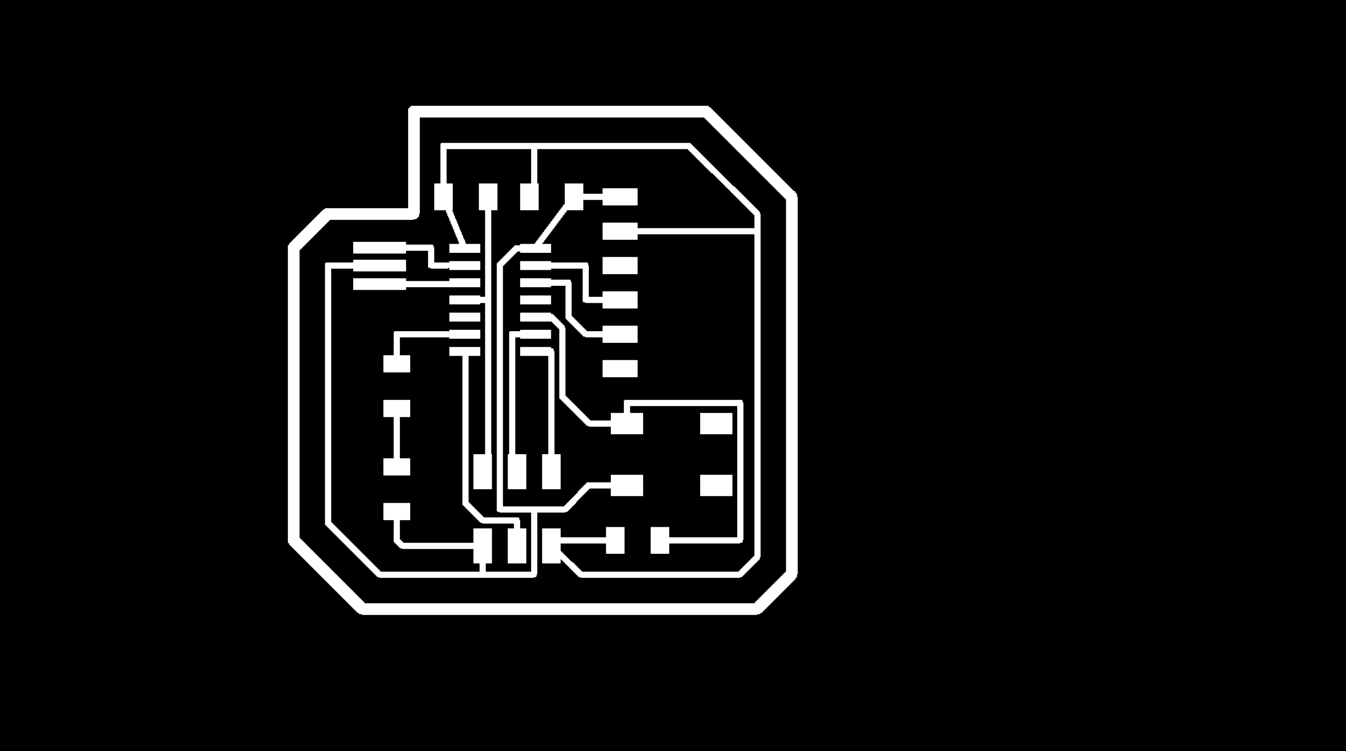
Step 13
the exported image should look something like this
Step 14
open photoshop to export traces PNG
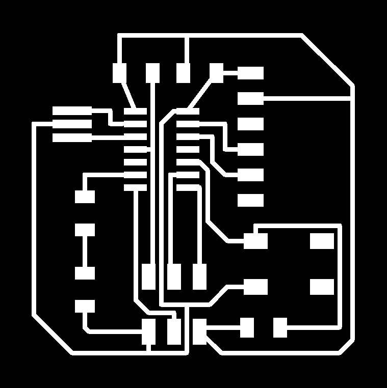
Step 15
Also used photoshop to export outline PNG

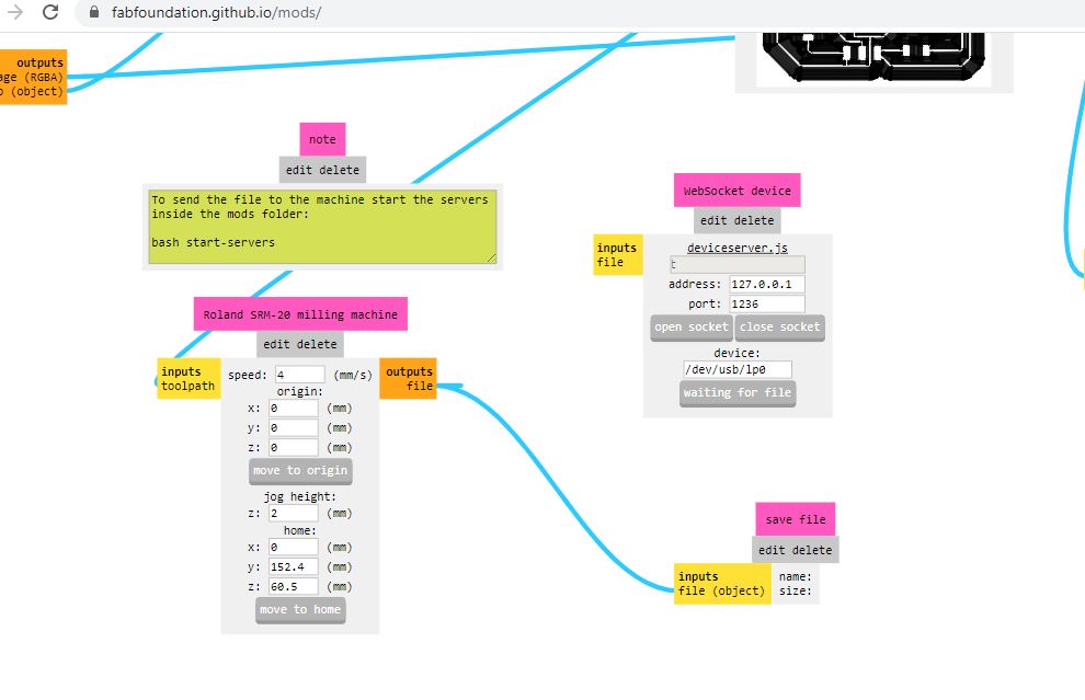
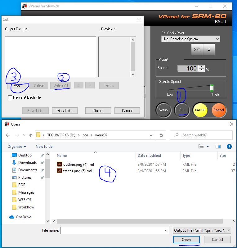
step 16 Using mods upload the traces PNG
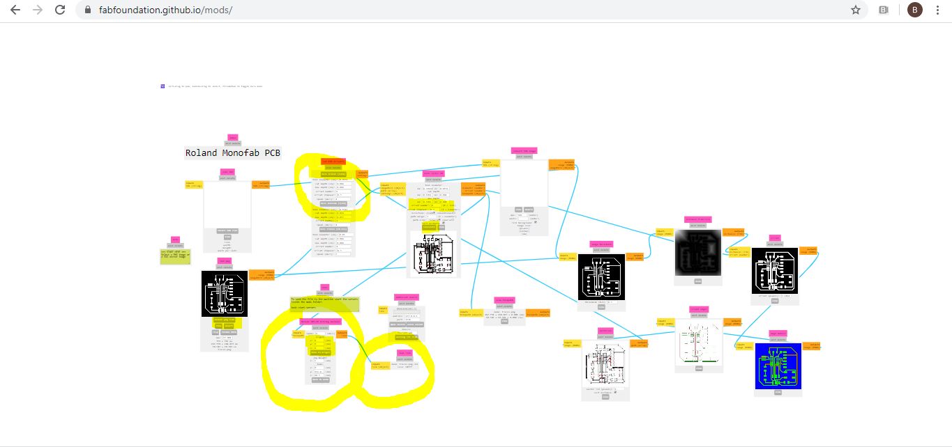
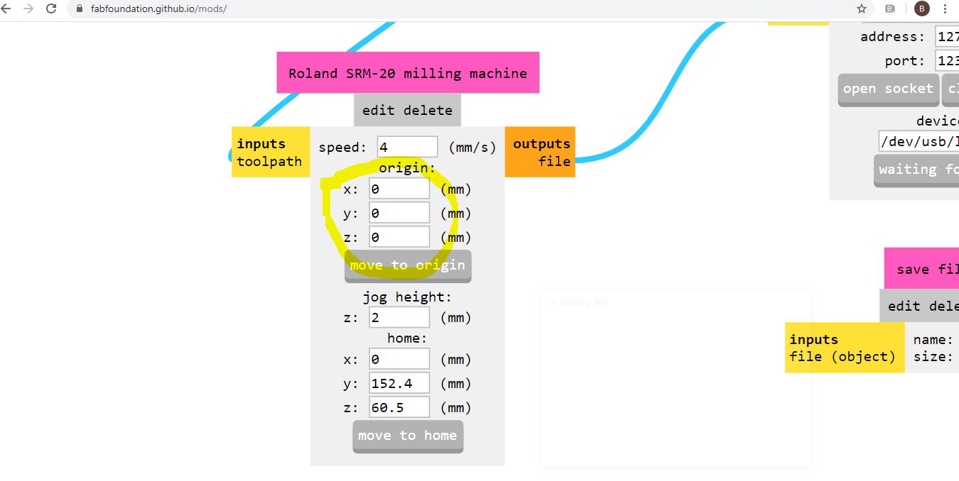 remeber to put al axis 0
 Saving the PNG
 repeat for outline AKA. interior
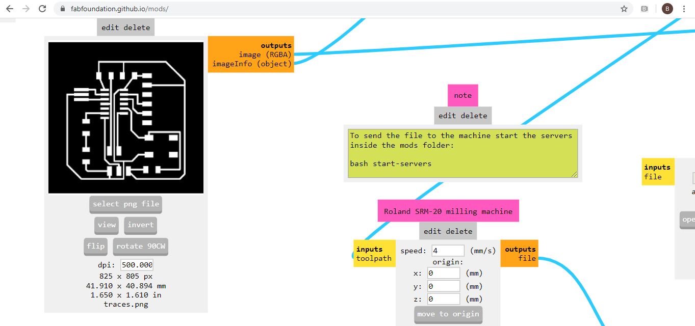 but i have discovered i forgot to change resolution once i uploaded as well as image size exported from photoshop changed compared to the exported image from eagle (so instead of width being almost 4 cmm became 29 cm )so i re-did all the above


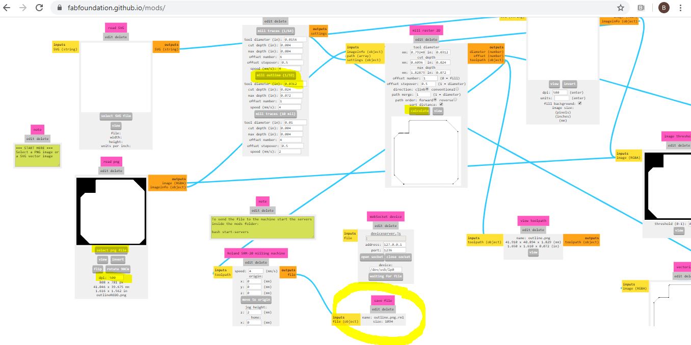
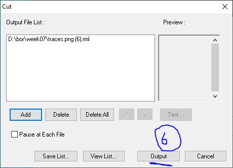
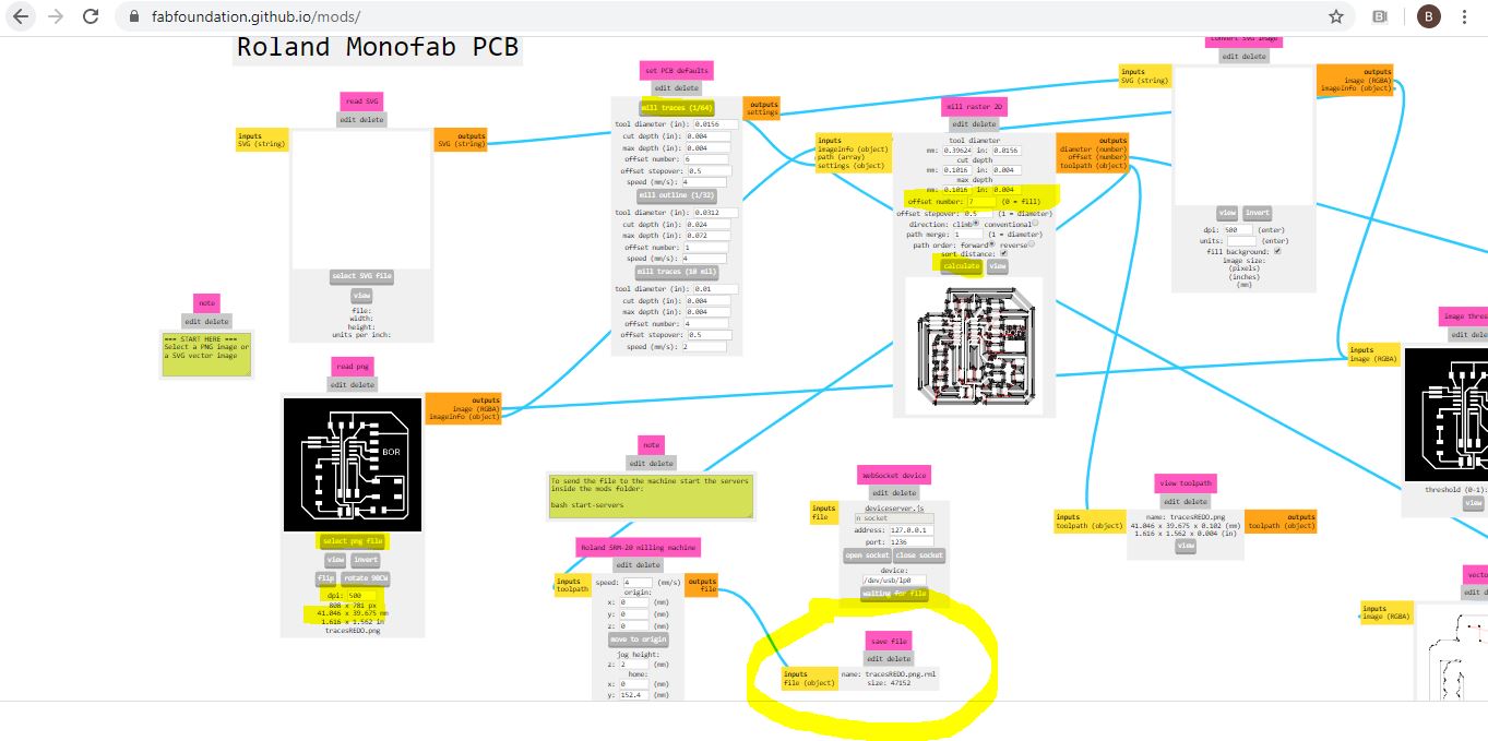 Plug in the save button to save …
Now moving to the machine after changing the milling bits, for traces 1/64” (0.4 mm), and for interiors 1/32” bit (0.8 mm).
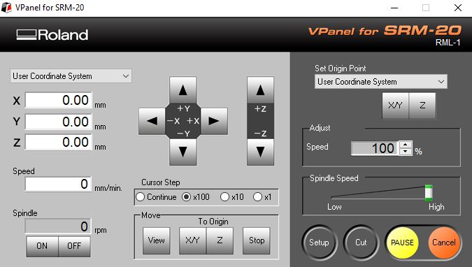
Step17
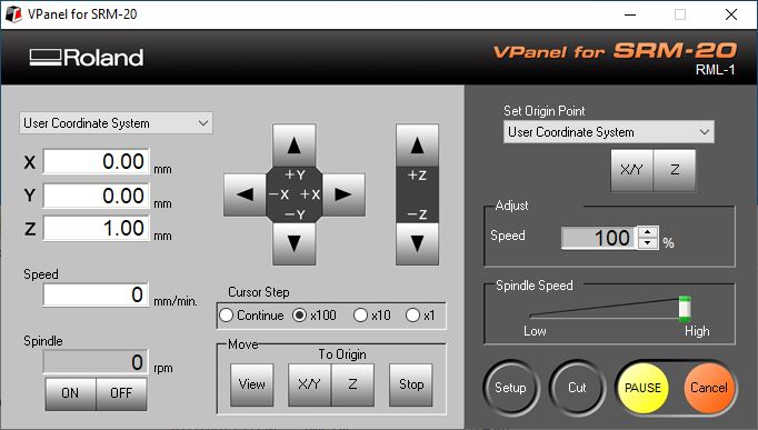
setting you origins X/Y … then Z
but then move the Z one mmm (just in case)
Step18
Take out the board you cut and take a cool video of that wink emoji
Step 19
Gather components to start soldering
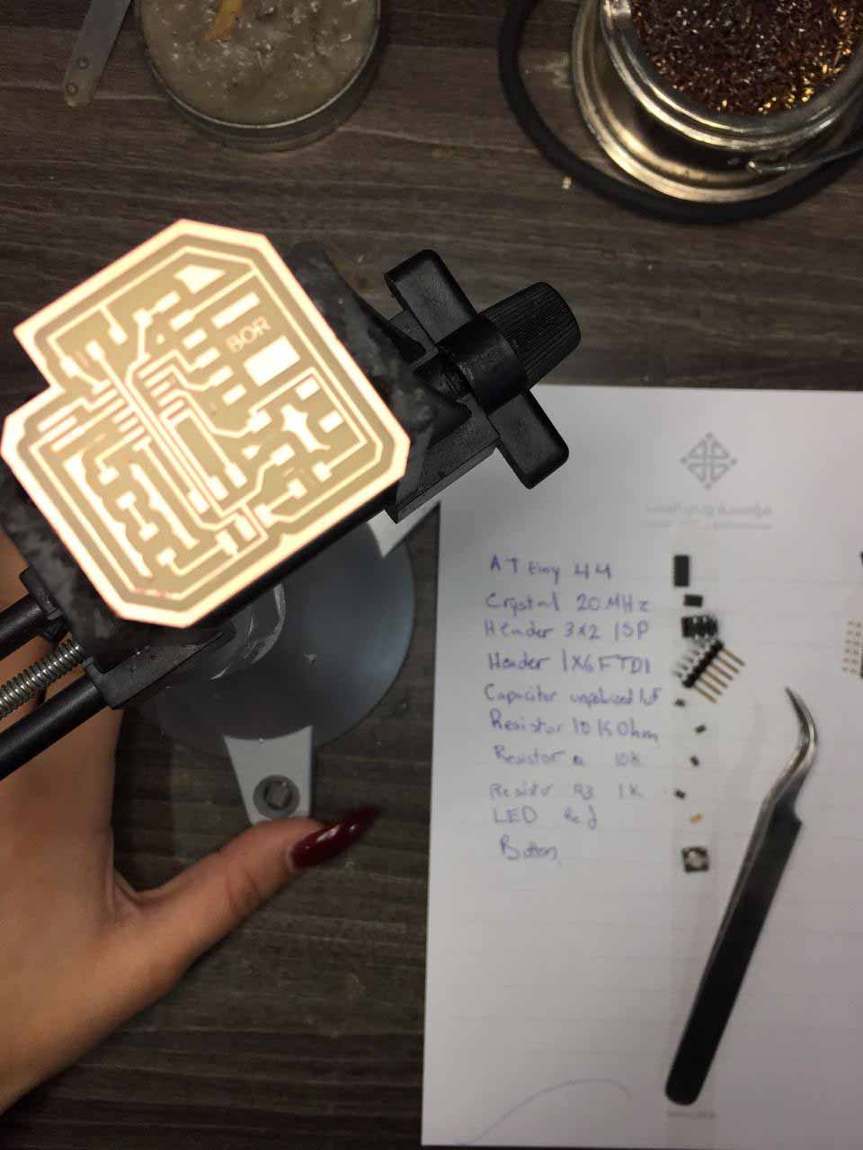
Step 20 For soldering I used the chart below exported from eagle after turning all layers “on” (from layer setgtikngs - Show layer) to follow up
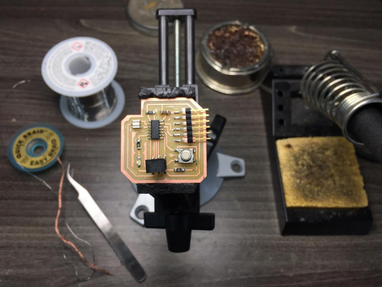
Step 21
Hero Shoot!
Conclusion
0-Check with multimeter the board alone before soldering a)Micro processor b)ISP c)FTDI
1-Check with multimeter the connection between components after soldering same order as point 0
(one point with al the other points)
2- Kindly check the clearance as once export from eagle traces 16 , clearnance 16 isnt enough must be at least 18!
to avoid such short circuts like what happened with me at first as you see in the circle where i scratched with a cutter.
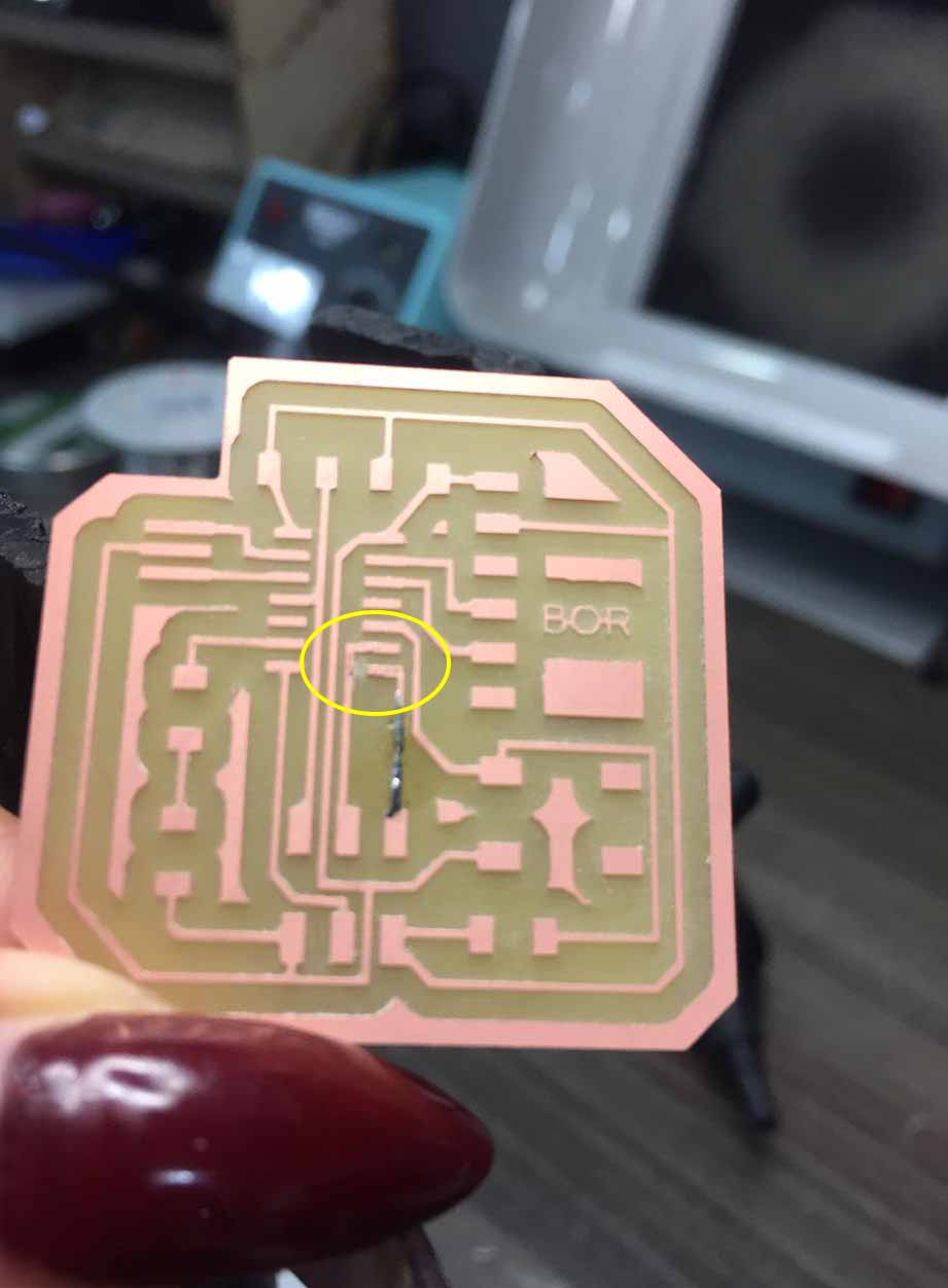
with multimeter better use oscilloscope
Programing
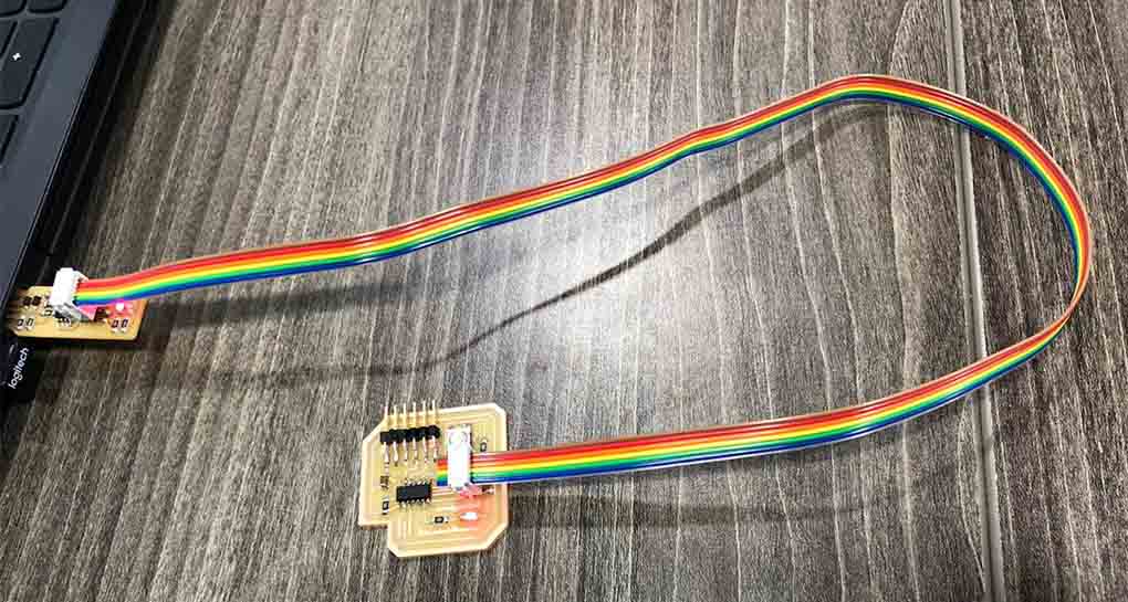
i uploaded the code using Arduino software after downloading few libraries for the windows check the embedded programming for more details … so after the computer recognized the ISP of the PCP i connected the ISP PCP to the ISP of my board then on Arduino software i recognized its appearing and was able to transfer the code
Code
Traces Code
// the setup function runs once when you press reset or power the board
void setup() {
  // initialize digital pin 12(transistor) as an output.
  pinMode(13, OUTPUT);
}

// the loop function runs over and over again forever
void loop() {
  digitalWrite(13, HIGH);   // turn the transistor  on (HIGH is the voltage level)
  delay(10000);                       // wait for 10 seconds
  digitalWrite(13, LOW);    // turn the transistor off by making the voltage LOW
  delay(10000);                       // wait for 10 second
}