5. Electronics production
- Characterize the design rules for your PCB production process
- Make an in-circuit programmer by milling and stuffing the PCB,test it, then optionally try other PCB processes
Machine : Roland monoFab SRM-20 Capable of 3D milling, 2D Milling, and Engraving.
Files to download
mods
Individual Ass
preparing the file on mods:


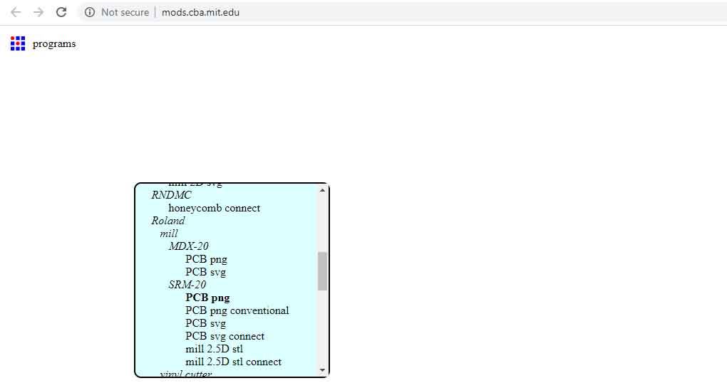 Right click on the mods interface to open the selection list. Click on programs > open server program > machines > Roland > mill > SRM - 20 > PCB png
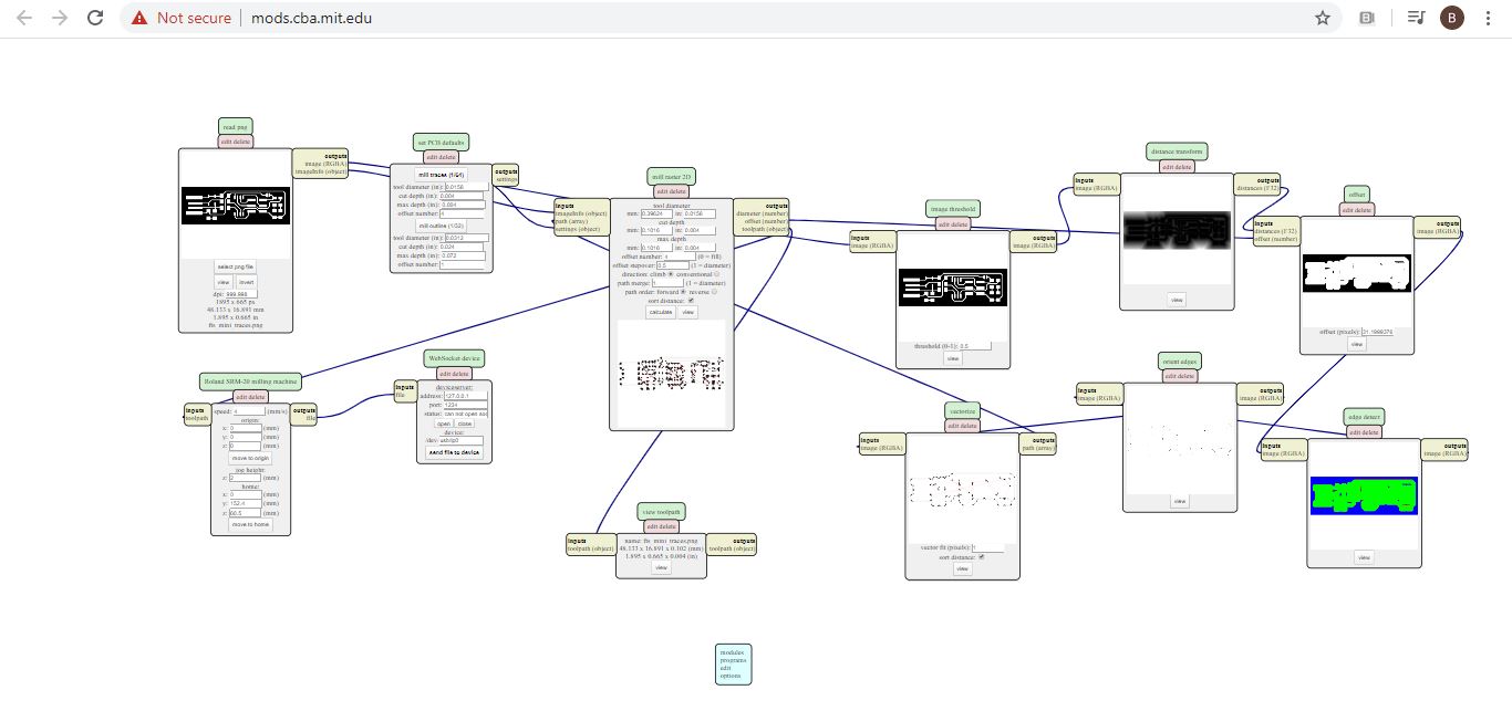
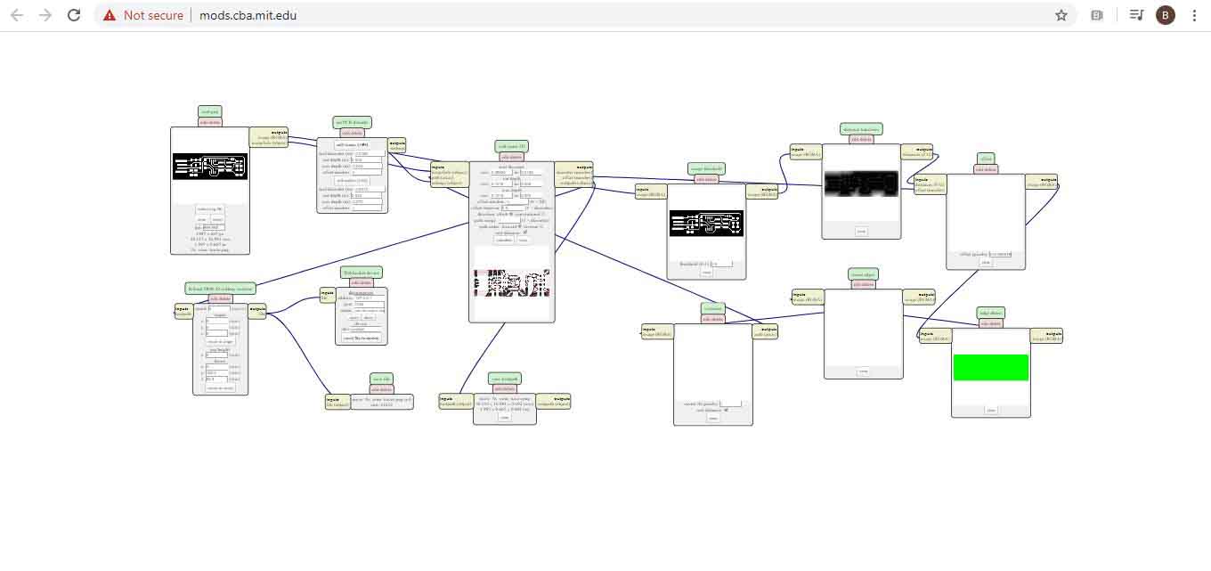
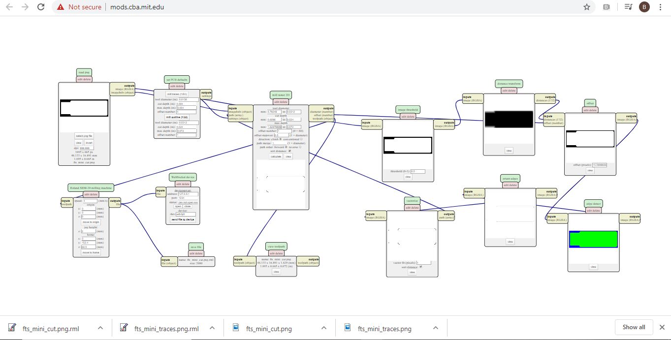 Clicking on “mill trace (1/64)” to select the right milling bit. The copper base thickness of the FR4 PCB is 0.1 mm. “Cut depth” is set to 0.004” (0.1 mm). “Offset number” controls the milling spacing around traces. “Offset number” is set to 0, which means the spacing, where applicable, will be the maximum to have a clean cut (unwanted copper will be removed); 4 x 1/64” (0.4 mm) = 1/16” (1.6 mm).
As I’m working on windows I couldn’t control the machine from my laptop so I just saved the files to use
Clicking on “mill trace (1/64)” to select the right milling bit. The copper base thickness of the FR4 PCB is 0.1 mm. “Cut depth” is set to 0.004” (0.1 mm). “Offset number” controls the milling spacing around traces. “Offset number” is set to 0, which means the spacing, where applicable, will be the maximum to have a clean cut (unwanted copper will be removed); 4 x 1/64” (0.4 mm) = 1/16” (1.6 mm).
As I’m working on windows I couldn’t control the machine from my laptop so I just saved the files to use
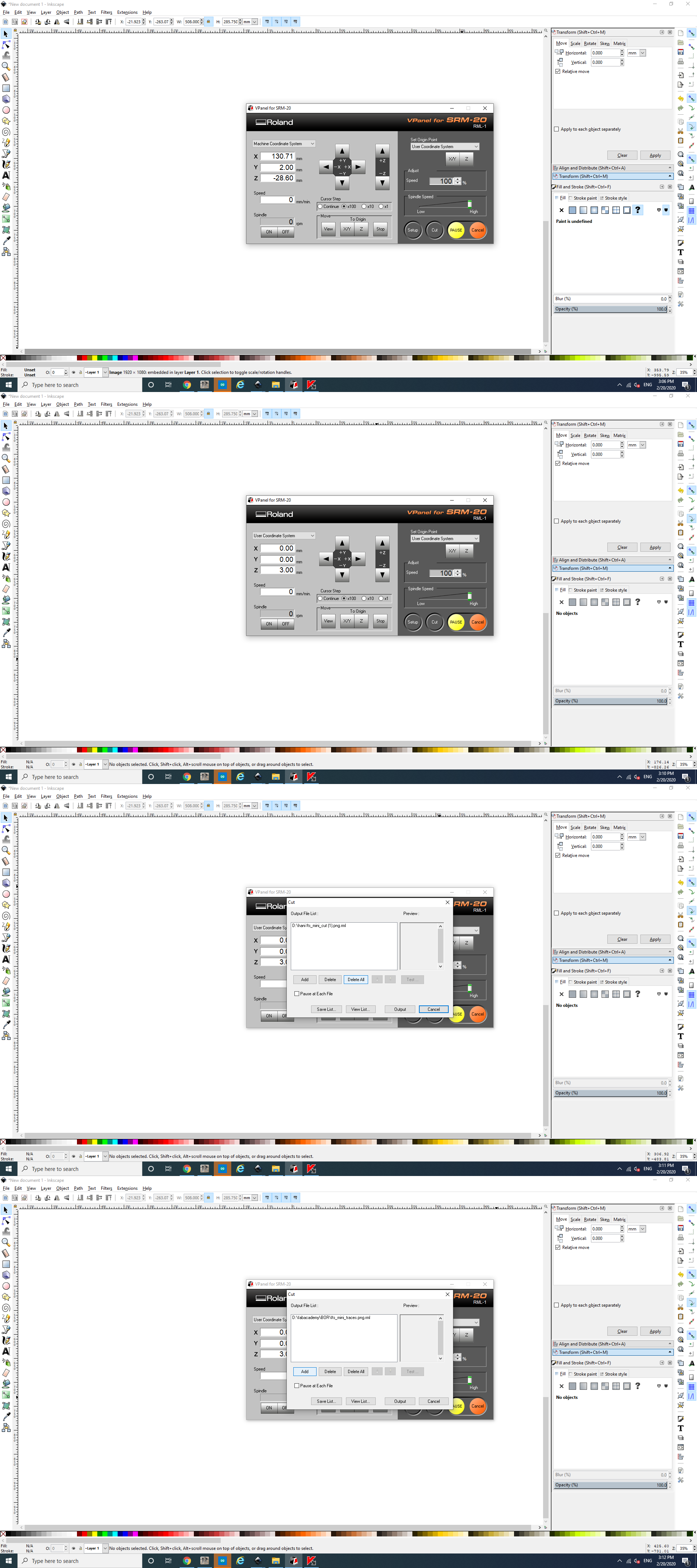
After the preparations of files above, it’s time to cut … 1-Opened the VPanel software and selected “Machine Coordinate System” option from the dropdown menu. Used the “+X, -X” and “+Y, -Y” arrows to move the head over the bottom left corner of the PCB. Used the “+Z” arrow to have enough space between the spindle and the PCB to insert the milling bit.
2- Inserted the 1/64” milling bit in the spindle collet leaving about 25% of its length outside. Tie the fixing screw.
3- Using the “-Z” arrow, moved the spindle down till there is about 5 mm between the PCB and milling bit tip. Held the milling bit between your fingers and untie the fixing screw then the milling bit down till it touches the PCB. Tied screw firmly. This is my start position.
4- From the “Set Origin Point” dropdown menu to the right, made sure to select “User Coordinate System”. Clicked on “XY” and “Z”. This will define the current position as the home or zero position in the user coordinate system. Selected “User Coordinate System” from the dropdown menu to the left. The values of “X”, “Y”, “Z” should be zeros …but before started the machine i moved the z axis 2 mm up to give it space the spindle to turn around when the machine is on with no dmmage
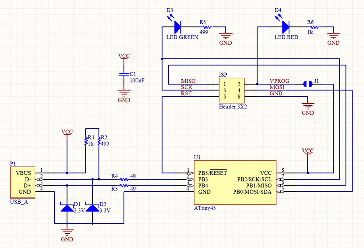
Components needed: * 1x ATtiny45 or ATtiny85 * 2x 1kΩ resistors * 2x 499Ω resistors * 2x 49Ω resistors * 2x 3.3v zener diodes * 1x red LED * 1x green LED * 1x 100nF capacitor * 1x 2x3 pin header
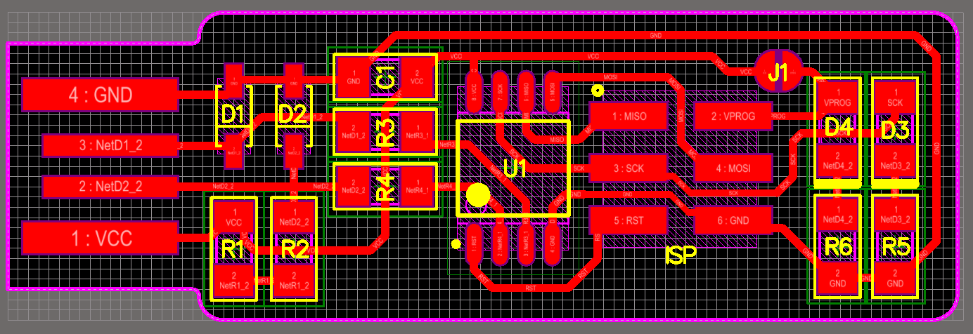
Solder the parts to the PCB, according to the schematic and board image from the links below as a reference for component values and placement.
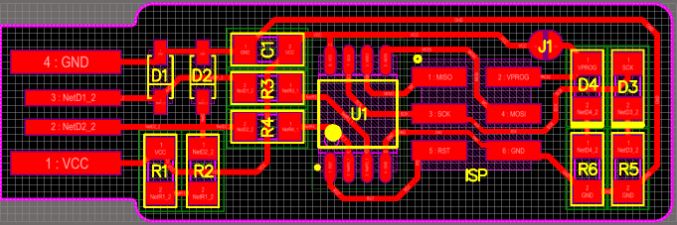 The LEDs and their associated resistors are optional; the red LED lights when the target circuit is powered, and the green LED lights when the programmer is talking to the target.
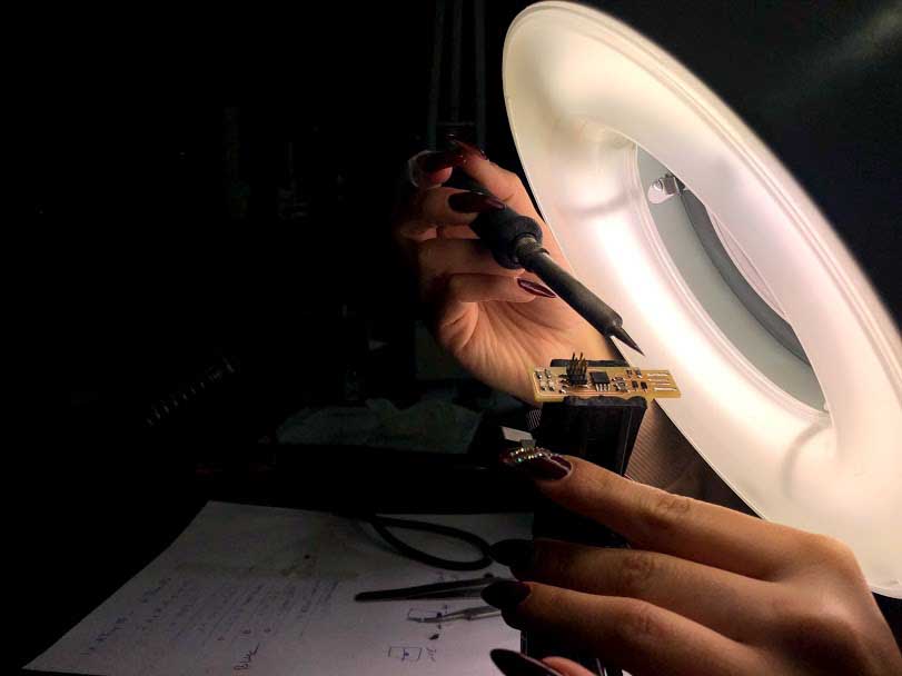
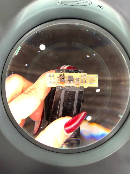
for soldering i used the schematic and board image as a reference for component values and placement. Started with the ATtiny45 first, so you have the most access. Installed the ISP header last (as it is large and can get in my way if i did it earlier. )
Soldering
Process Video
Hero Shot
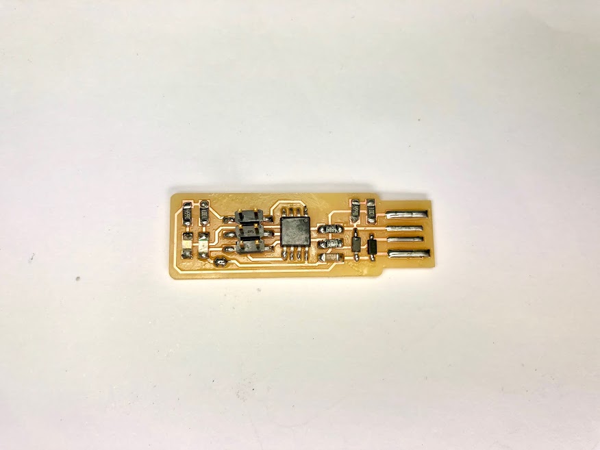
Thank you so much Brian Mayton for the the tutorial it helped.
Pluged the board into a USB port. I used a short USB extension cable (USB hub) or rather than plugging directly into the port, especially if your USB ports are upside down to reduce risk of damage to in built-in USB ports.
then steps in this order - Run make
-
Run make flash … used ATtiny45 installed in the correct orientation and soldering is ok and ISP header … then
-
Run the make fuses command
- Run make rstdisbl
After that Test the USB Functionality. Windows lists USB devices in Device Manager (Start → Control Panel → System → Device Manager), though it doesn’t always tell what they are until the correct drivers are installed.