7. Output & it’s packaging
since I wanted to just move the spikes as my original sketch & concept regarding the final project… i tired several methods of moving the spikes …Firstly i tried with:
-
Nitinol Then
-
Solenoid Then
-
Servo motor with some mechanical parts attached to it that i agreed to use finally
Nitinol
Arduino
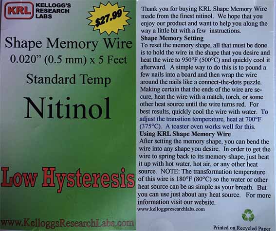
Nitinol datasheet
Carefully read this datasheet to know the instructions how to program this specific Nitinol wire. Here what I used
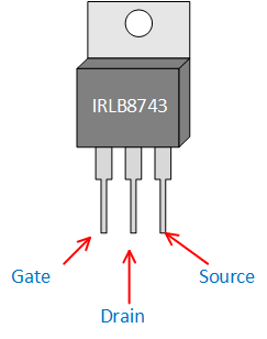
IRB8743 mosFET transistor (N channel) pin configulation
Details of the Transistor switch
Breadboard view of the Transistor Switch. SMA or Coil is connected to the Battery*. If you are using 9V battery, make sure to use resistor (3W or 5W) between battery and SMA/coil so you do not exceed maximum current.
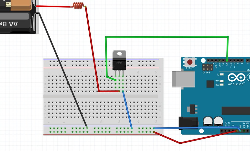
Now you can upload the “Blink” example code from File/Examples/Basics/Blink and see if it works. Make sure to adjust the on/off timing of the code so you do not activate the coil/SMA too long.
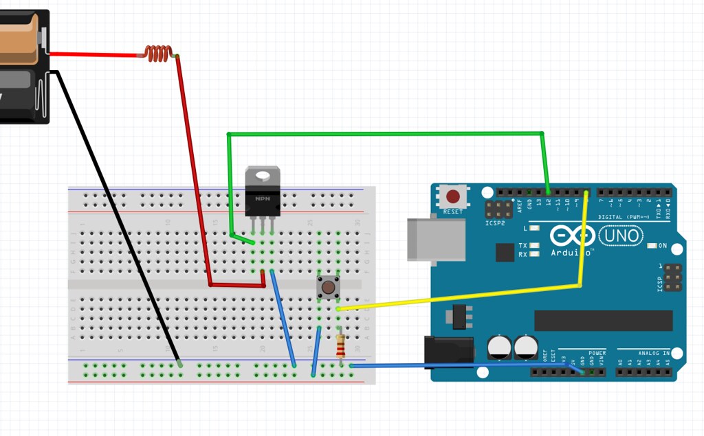
Breadboard view of the Transistor Switch with a push button. Do not forget to add pull-up resistor to the button. The size of the pull-up resistor should be 10K ohm or bigger.
Code
Blink Code.
// the setup function runs once when you press reset or power the board
void setup() {
  // initialize digital pin 12(transistor) as an output.
  pinMode(12, OUTPUT);
}

// the loop function runs over and over again forever
void loop() {
  digitalWrite(12, HIGH);   // turn the transistor  on (HIGH is the voltage level)
  delay(10000);                       // wait for 10 seconds
  digitalWrite(12, LOW);    // turn the transistor off by making the voltage LOW
  delay(10000);                       // wait for 10 seconds
}
SMA Example projects
Animated Vines by Jie Qi
Bacterial Motility by Erdem Kiziltoprak
Hylozoic Ground by Philip Beesley
The Culture Dress by Afroditi Psarra and Dafni Papadopoulou
SMA Tutorials
Further research about the atoms movement explains how “twinning” in the crystal structure of nitinol produces the memory effect
SMA preparations
SMA remembers 1 shape by training it. Note that it does not remember 2 shapes. When heated over certain temperature (refer to the datasheet of the Nitinol to know that temperature), it goes to the shape that is trained, but it will not go to another shape when it is under that temperature. So, when you want to move surface with SMA, you need to plan how it returns to original position from heated state position.
After reading the datasheet and preparing it
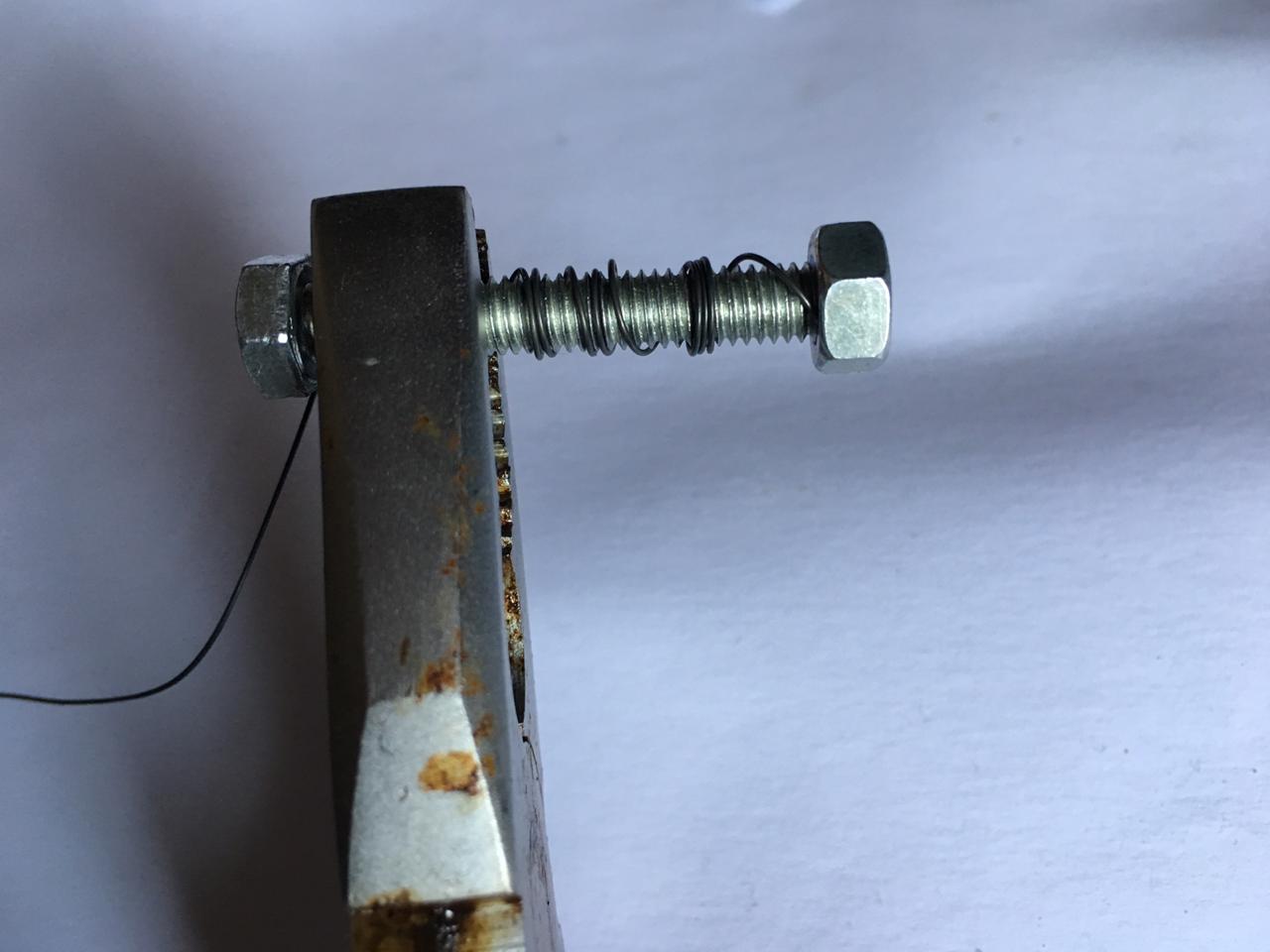
step1: roll the nitinol on the nail (for the curl) an attach it strongly (bcuz its strong to heat/program otherwise)

step2: Program the nitinol/ heat for few seconds aunti,l the metal turns red

stetp3: place immediately in cold water
step3: test if it worked and nitinol was programmed by either exposing it to hairdresser hot air or placing it in hot water (after you try to stretch t by hand to almost straighter shaper but please dont over stretch it so it wont break) … in the video below i plqaced it in hot water and kindly notice how it curled again in hot water which means the programming face worked
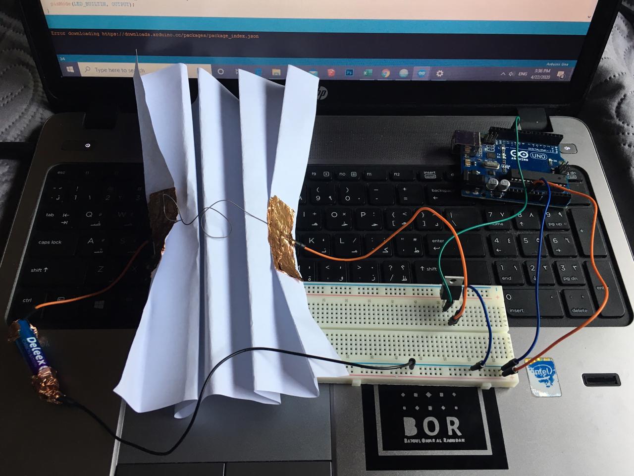
step4: Nitiol circuit i followed this diagram to make the circuit … by cutting cuppor attaching it to cardboard/paper and soldering components also used this website to know the to determine the value and tolerance of the resistors resistor calculator
step5: i attached everything physically and connected Arduino to blink code and modified the code to 10 seconds as nitinol needs almost minimum that time to start actually seeing it move
SMA Smocking attempts
Due to the COVID-19 lockdown/ Curfew and shortage of materials I just tried with paper instead of fabrics so here’s the trial…
SMA Smocking Examples
tried Small push-pull solenoid too but i didn’t like
then i tried servo motor and i saw potentials in it so i would use it for the final project
Servo Motor
I used HobbyKing™ HK15138 Standard Analog Servo 4.3kg / 0.17sec / 38g
HobbyKing™ HK15138 Servo Datasheet
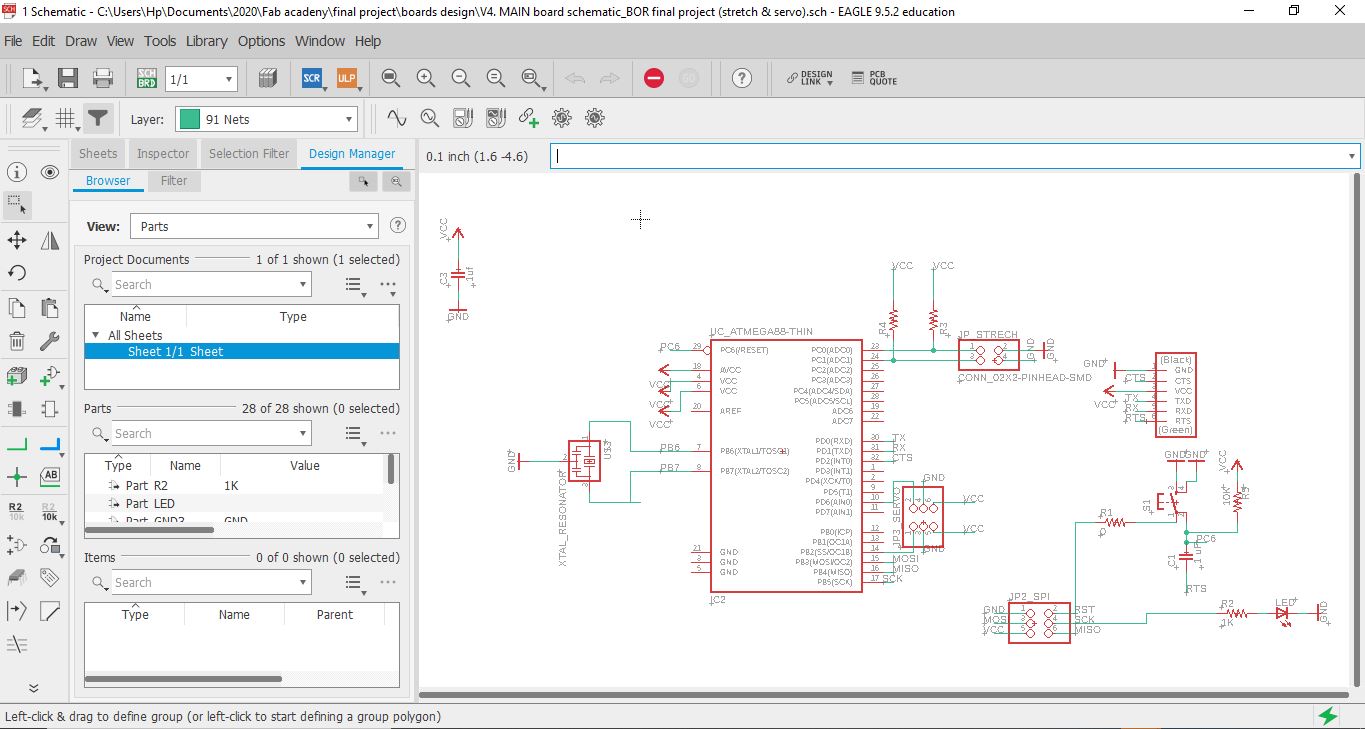
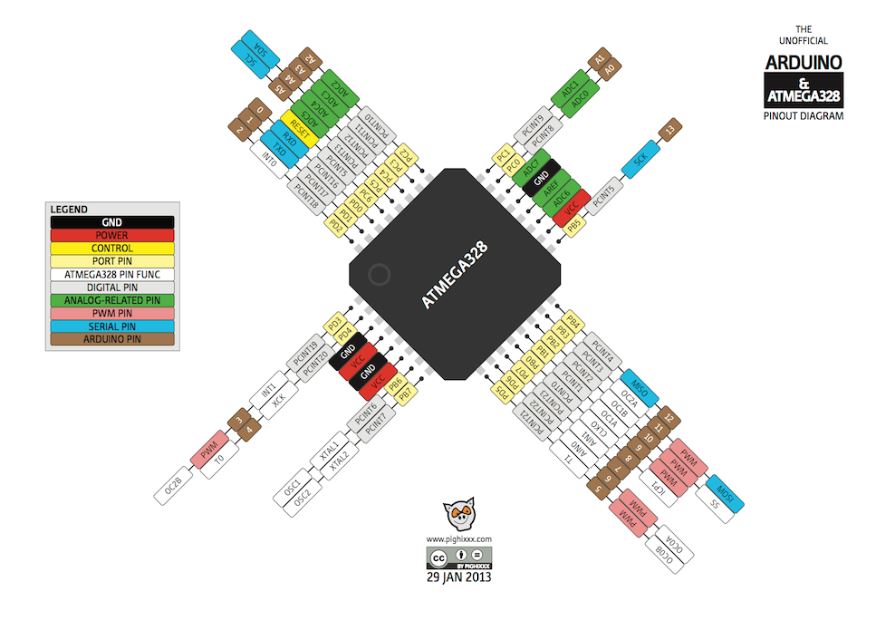 so here I paid attention to using the right pins that serve the Servo Motor Pin number 6 for example because its PWM which is Pulse Width Modulation, is a technique for getting analog results with digital means that i need for the servo motor.
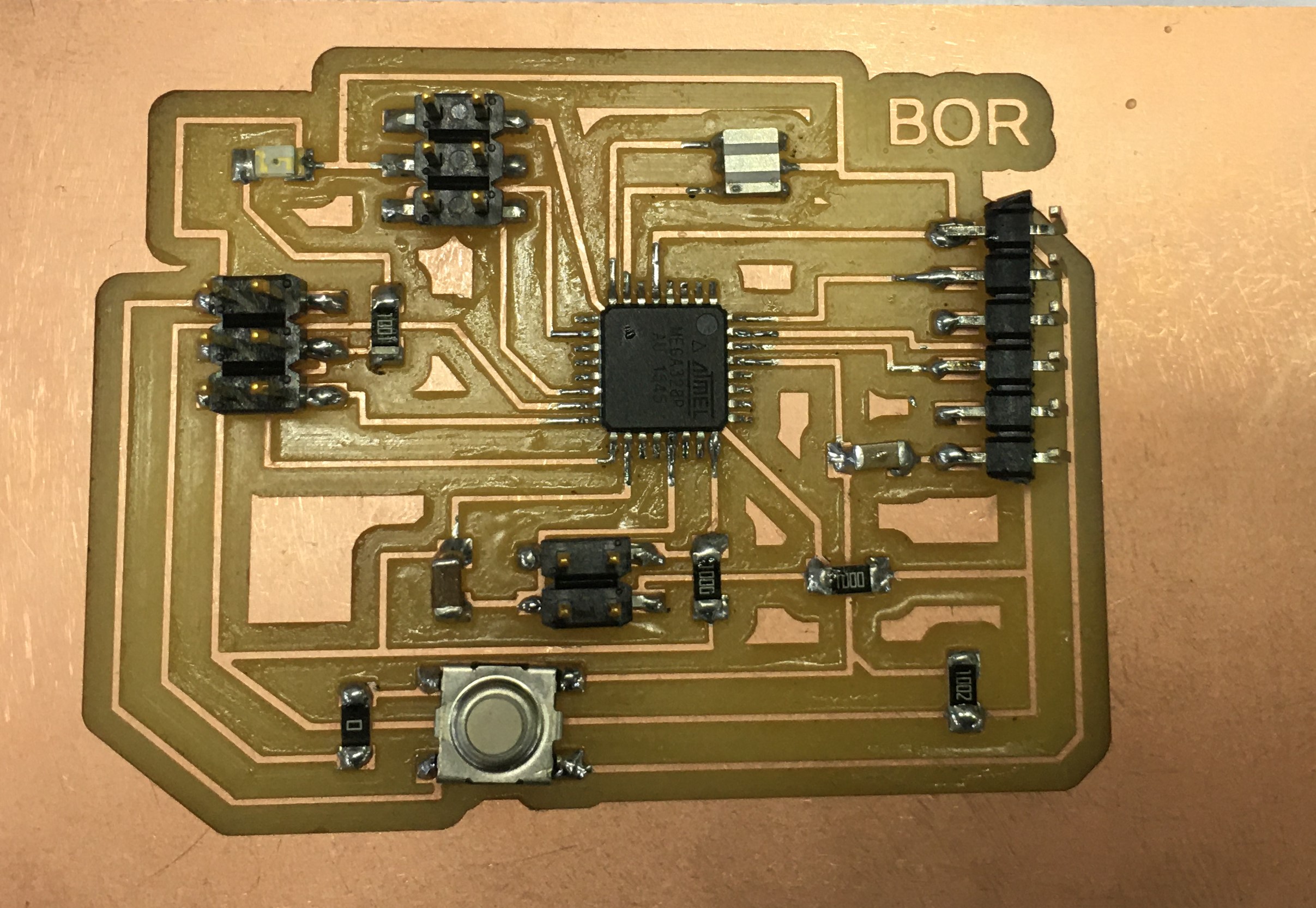
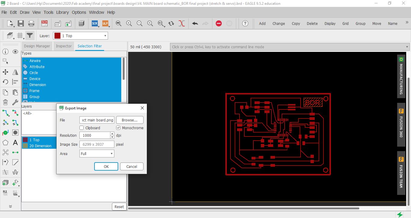 here you can see the board design after I successfully routed all the connections
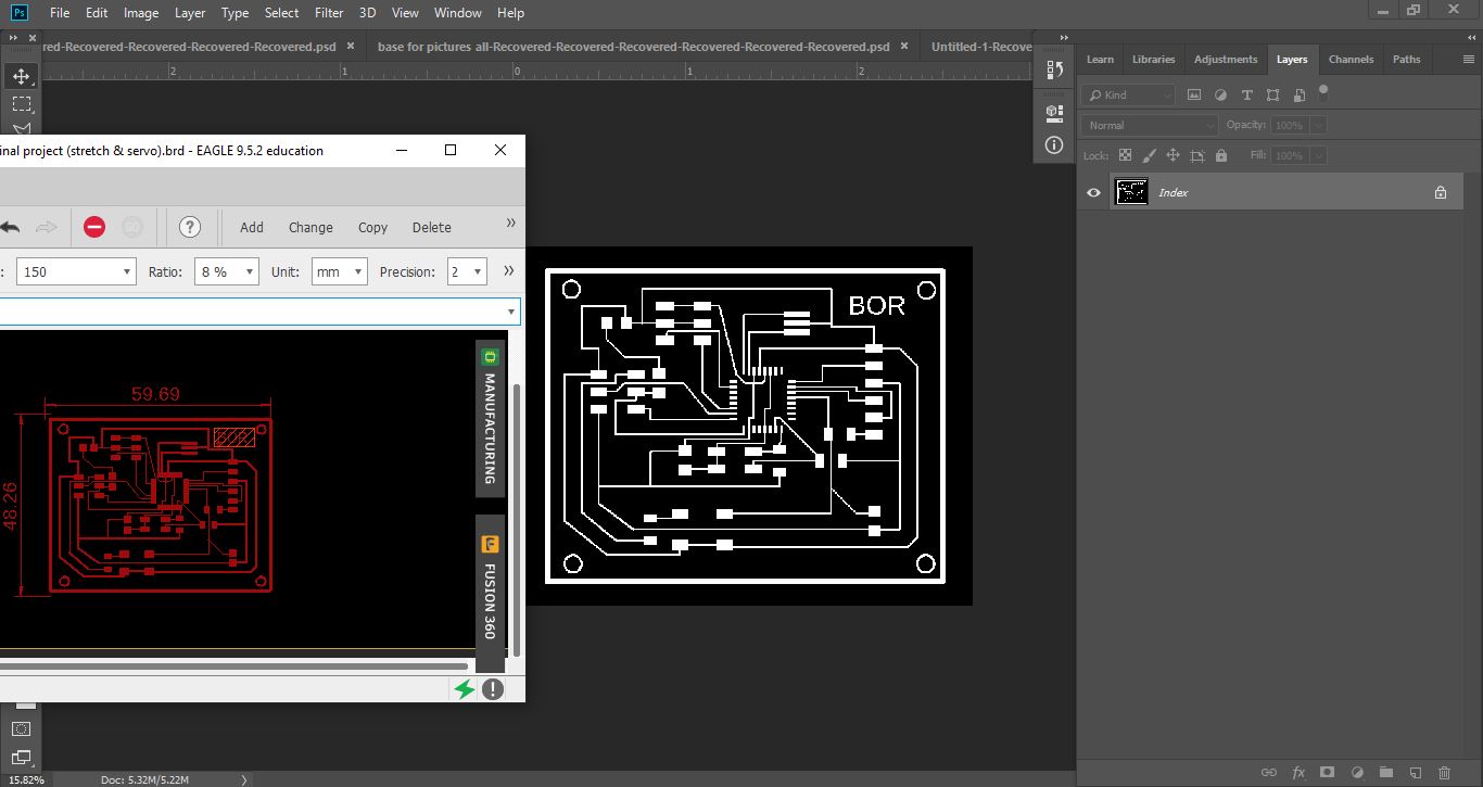 I exported my design and edited it using Photoshop in order to get the traces and the interior “outline” PNG
 a previous designed i designed for the servo and trestch sensor but didnt work it somehow and i tried to figure out why but ended up making another one from scratch which is the final result below
Finally i have the new design all ready so here is the traces and the interior “outline”
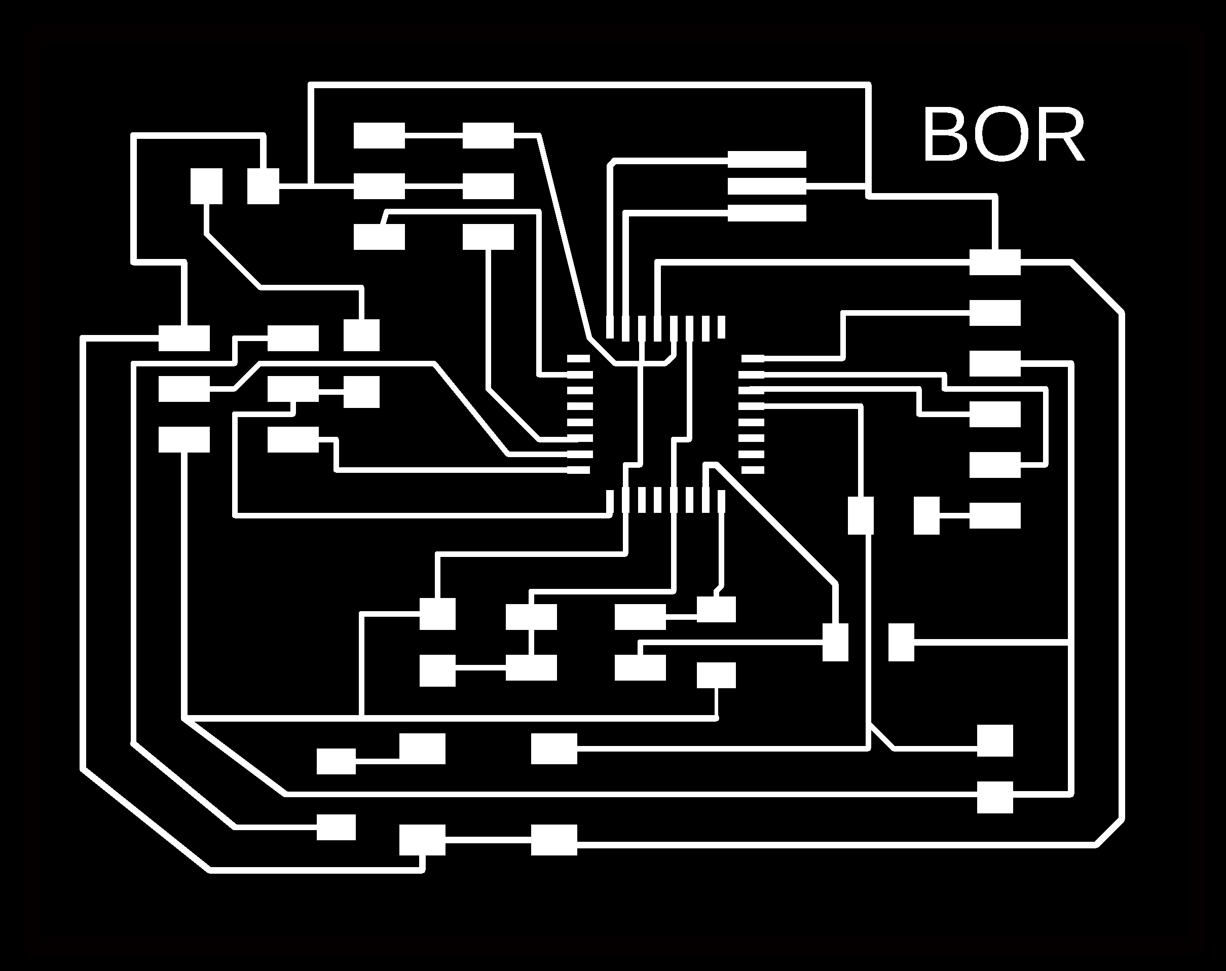

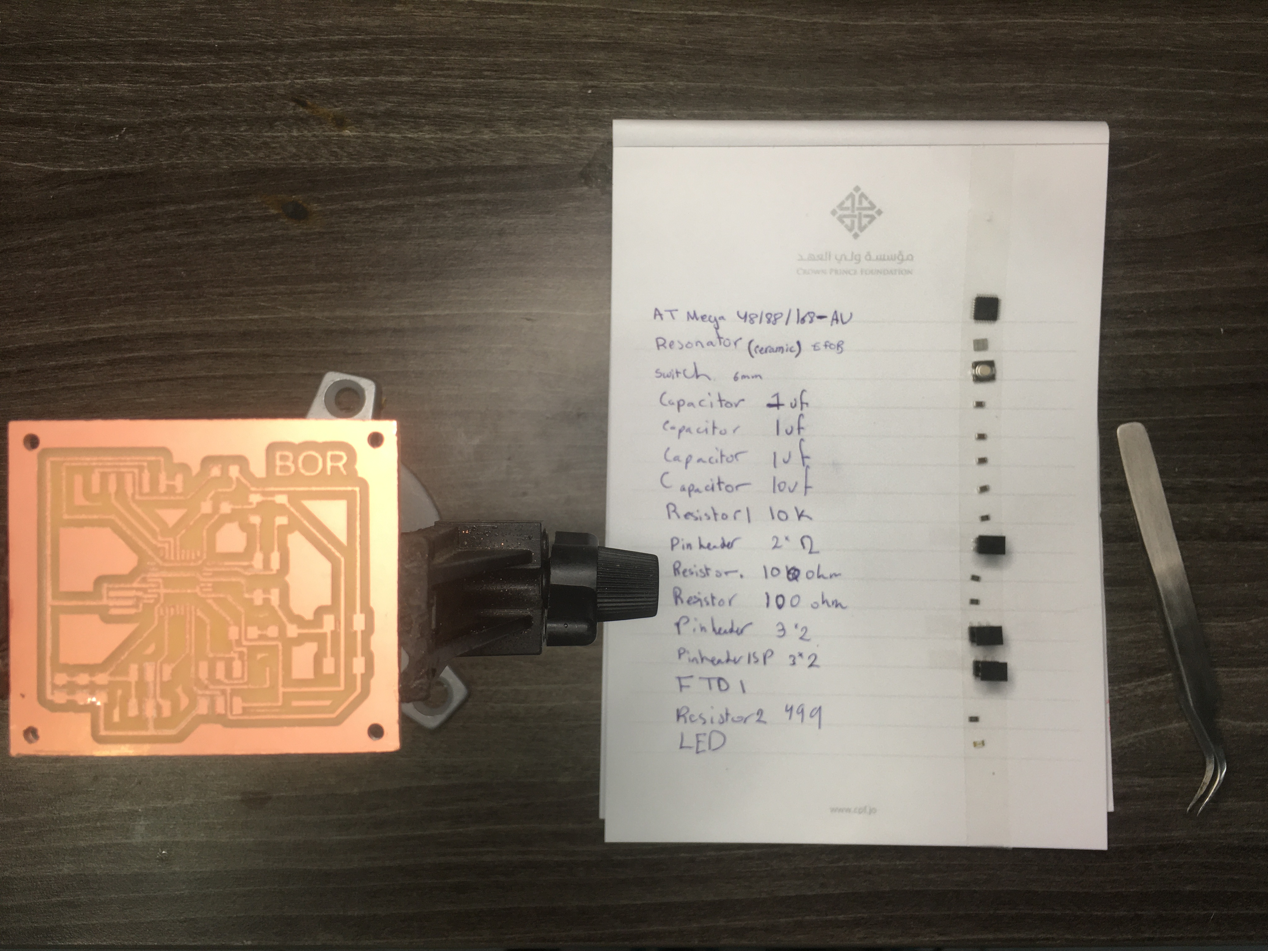
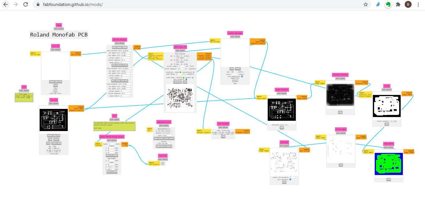
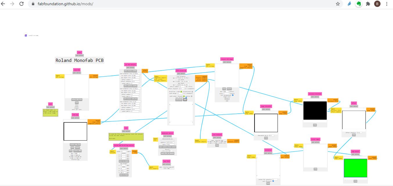
That i used later on mods to cut my via Rolan Monofab PCB machine
i used arduino to program my board after i downladed the need libraries for windows check week 9 for specific details
Final Code
Servo- Flex code … for my final project
#include <Servo.h>

Servo myServo;
int flexValue;
int servoPosition;
const int flexPin = A0;

void setup()
{
  myServo.attach(6);
  Serial.begin(9600);
}

void loop()
{


  flexValue = analogRead(flexPin);

  servoPosition = map(flexValue, 450 , 1023 , 0, 125);
  servoPosition = constrain(servoPosition, 0, 125);
  Serial.println(flexValue);
 // Serial.println(servoPosition);
  myServo.write(servoPosition);

  delay(100);
}
Hero shot
Mechanical Parts
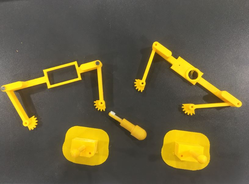
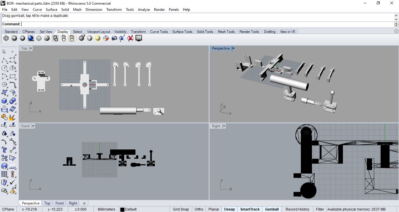 the design of mechanical parts based on the servo i used for final outcome
designing the mechanical parts attached to the servo was more of trial and error i kept designing pieces assuming they would work and then test them (by attaching them to the servo motor and and placing the small 3D printed on fabric above and see how the spikes move until i was satisfied)
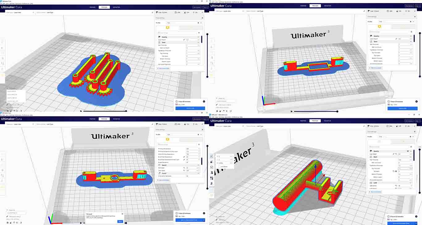 this the perfect servo mechanical parts that I settled for … regarding my final project and i liked the way it moves the spikes after doing many iterations as i mentioned above
integration
Flex sensor with servo - Testing with mechanical parts from Batoul Al-Rashdan on Vimeo.
Flex sensor with servo - Testing with mechanical parts- stem on from Batoul Al-Rashdan on Vimeo.
Flex sensor (fabric version) with servo - Testing with mechanical parts from Batoul Al-Rashdan on Vimeo.
controlling servo with arduino by my DIY flex sensor from Batoul Al-Rashdan on Vimeo.
Controlling servo motor with a DIY flex sensor from Batoul Al-Rashdan on Vimeo.
Board working check from Batoul Al-Rashdan on Vimeo.
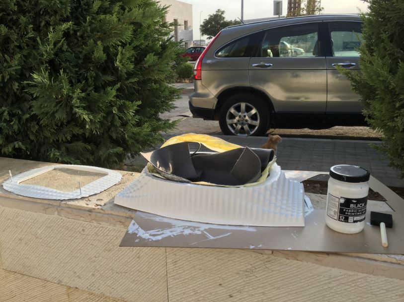
Silicone
Tried to use Week 16 to create stretch sensor with a silicone glove and then I changed my mind wanted to try it for output silicon on fabric so the servo moves underneath
I used SORTA-Clear™ 18
Food safety technical datasheet
Fabricated Trial number 1 (failed)
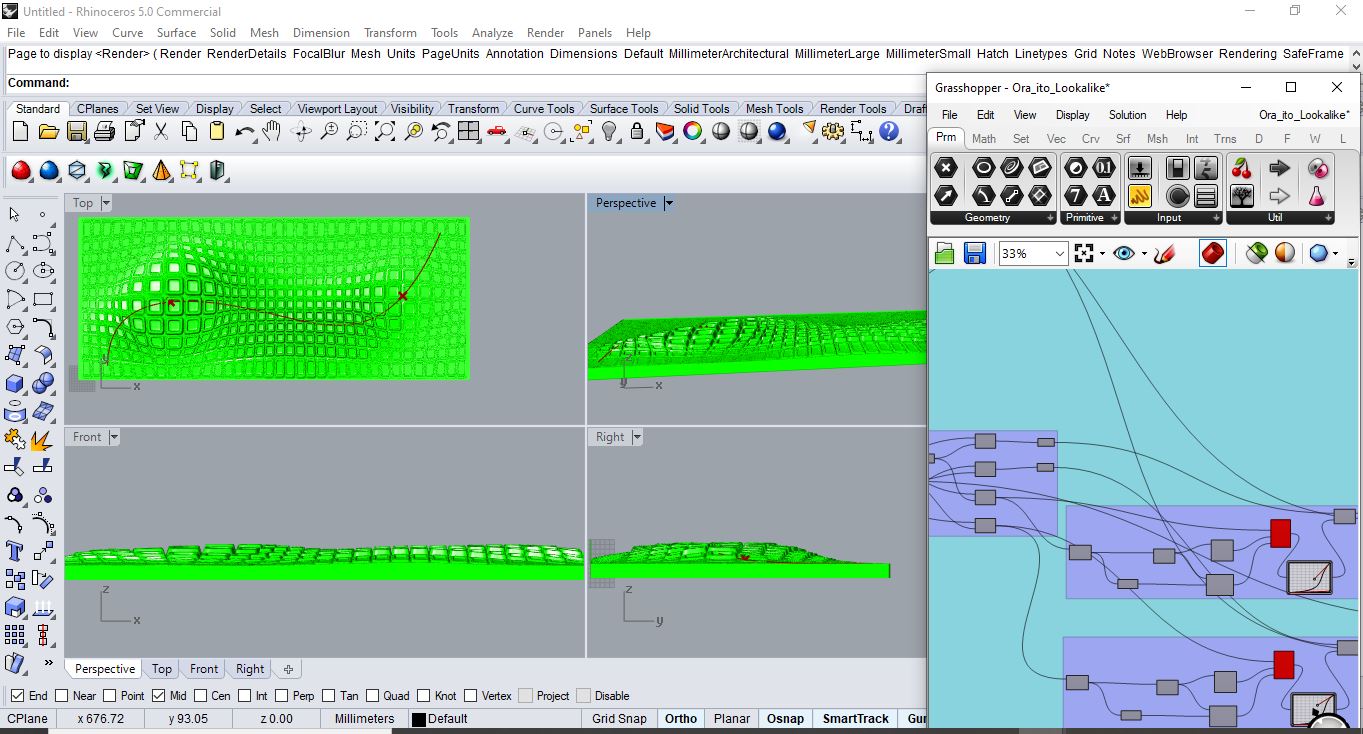 started by experimenting geometries using grasshopper that matches my original sketch for final project as a result wanted to create it as a mold (negative part) so i can get the positive of the geometry
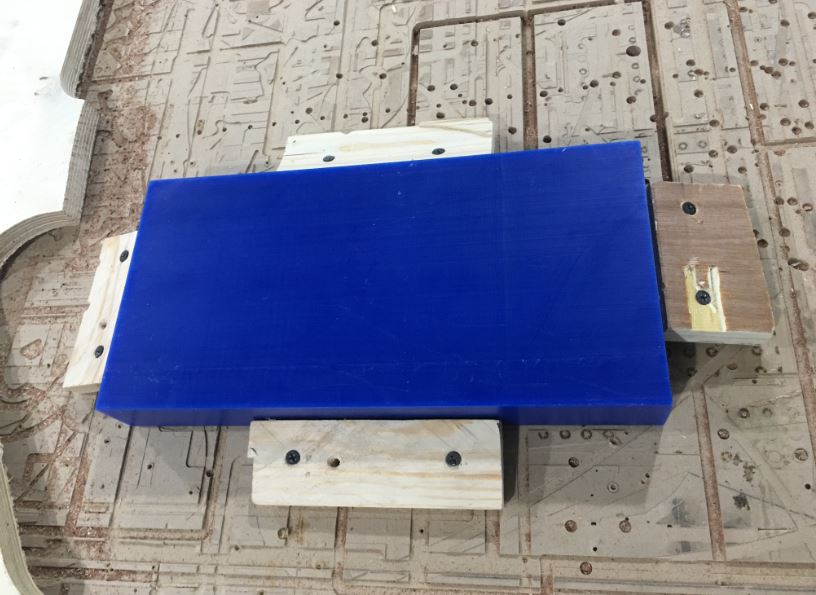 here i placed the wax and used waste wood to hang it in place as a result keep it attached to the bed while machine is running to get accurate results of the mold as the STL file
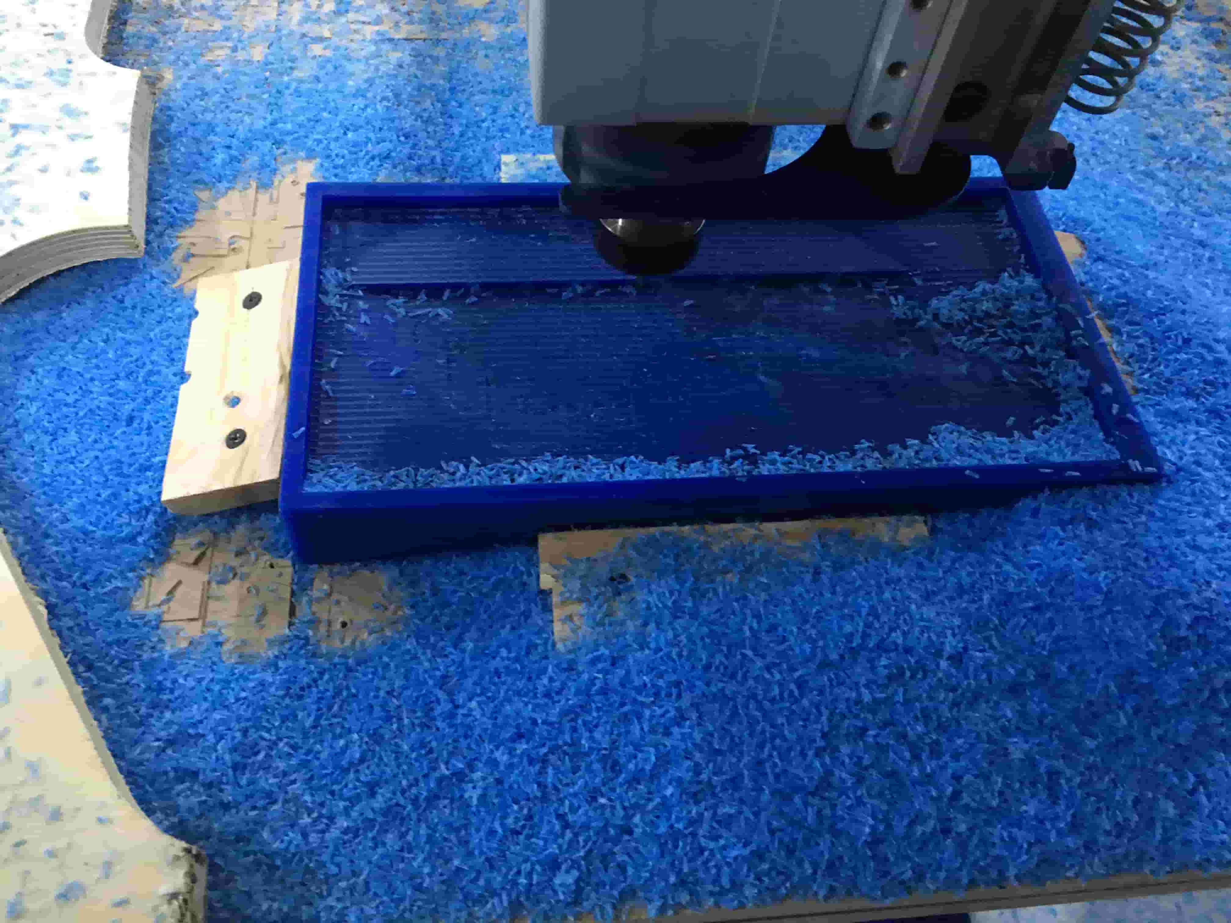 first step/job getting the rough finish
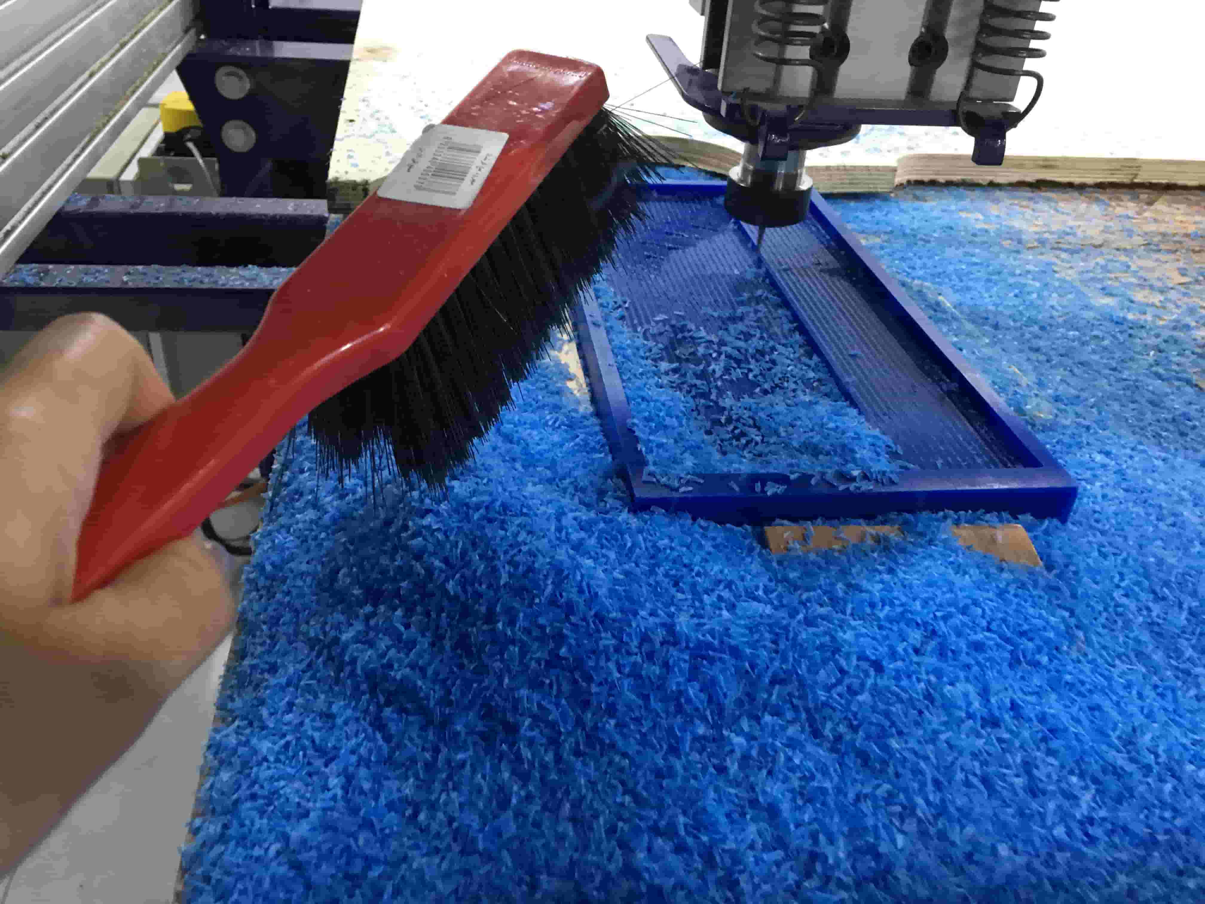 while observing the machine i made sure to keep removing excess wax away
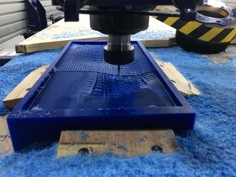 at this point we can observe the intermediate between the first rough finish and the detailed finish
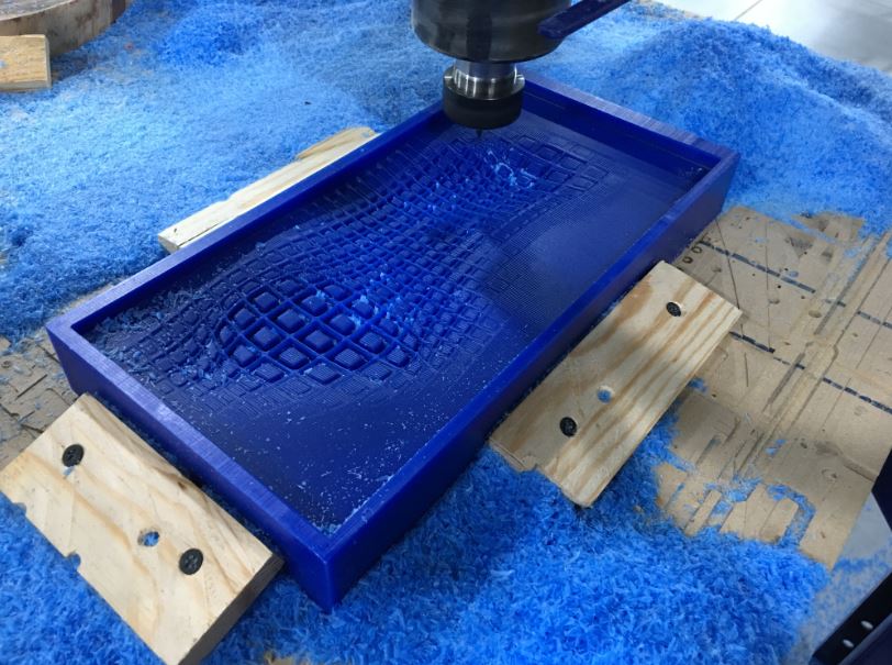 here a last capture making sure everything is fine before i detach the wax from bed … checking all details are fine and matching the STL file and design file and more things to do ( reached satisfaction in terms of levels of details)
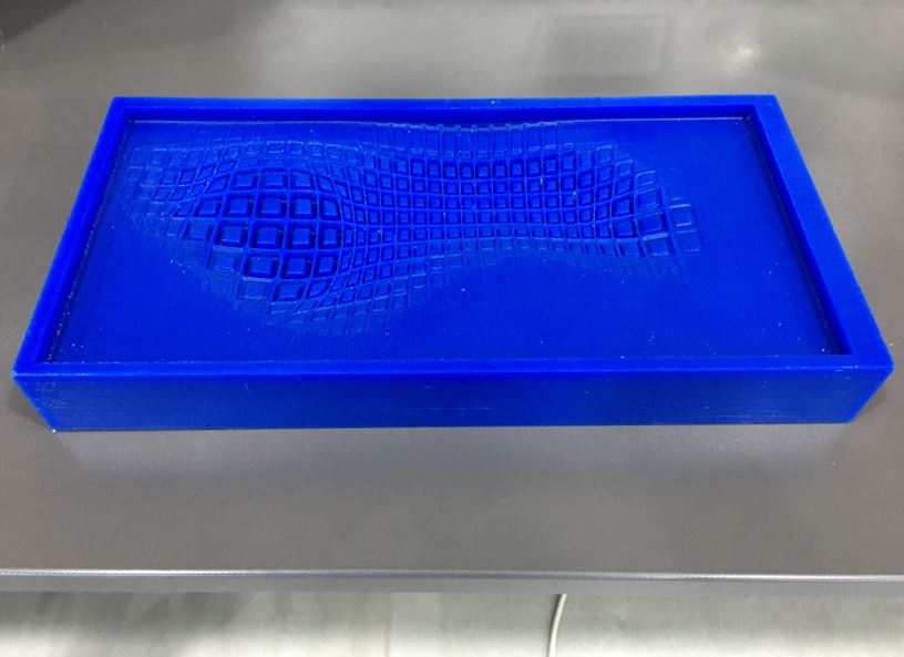 so this is the absolute final result as you can see so fine matching the level of details i have in mind as well the design file to a certain degree .... i was so happy and satisfied buttttt wait for it
3D Printing a spikes mold to try to get the true edge of a spike that the printer can’t produce due to extruder size … and machine limitations…
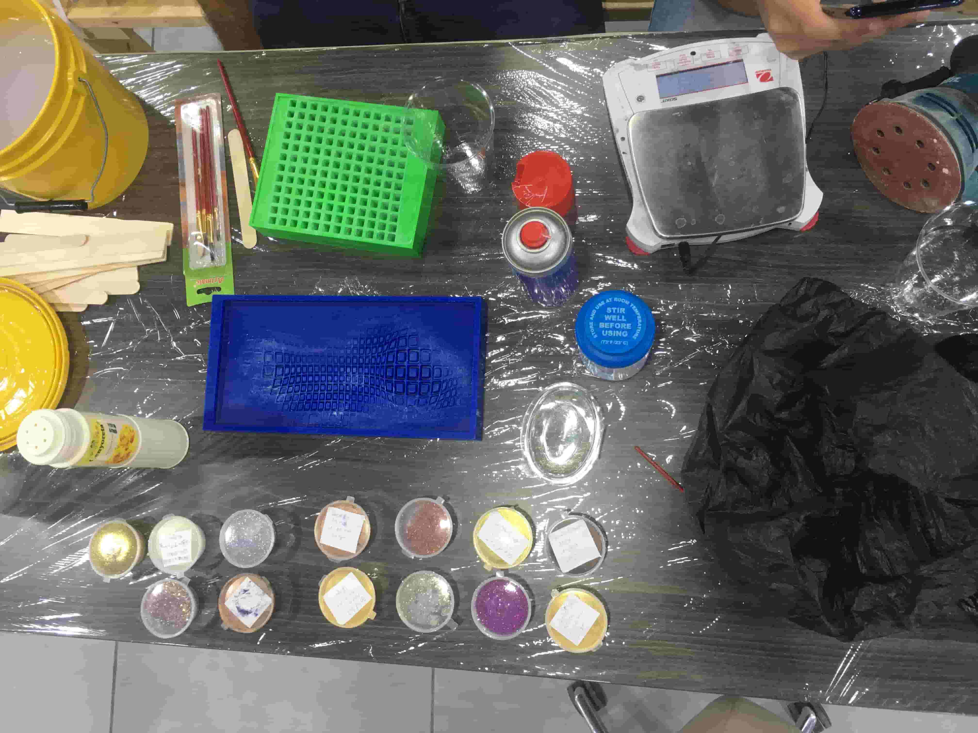 as I was doing this for my final project as a possibilities for the outcome (output) on a fabric (where the servo mechanical parts move underneath and i control all that by the stretch sensor /glove as input)… i wanted it to be extra cool! by adding colors to the Ecoflex (since eco flex is transparent i wanted to use that for my advantage) I added glow in the dark + metallic color to end up with a cool silicon color merged with my cool design (as this would be the fron piece of my moving art as the original sketch regarding my final project) and it was epic fail as it missed up with the chemistry of it! never dried but top layer dried… another theory is that the smaller recessed details in the geometry collected all oil and spray releasing agents and so once poured the silicone it never dried in these part which explains why dried from the top.
Hero Shot
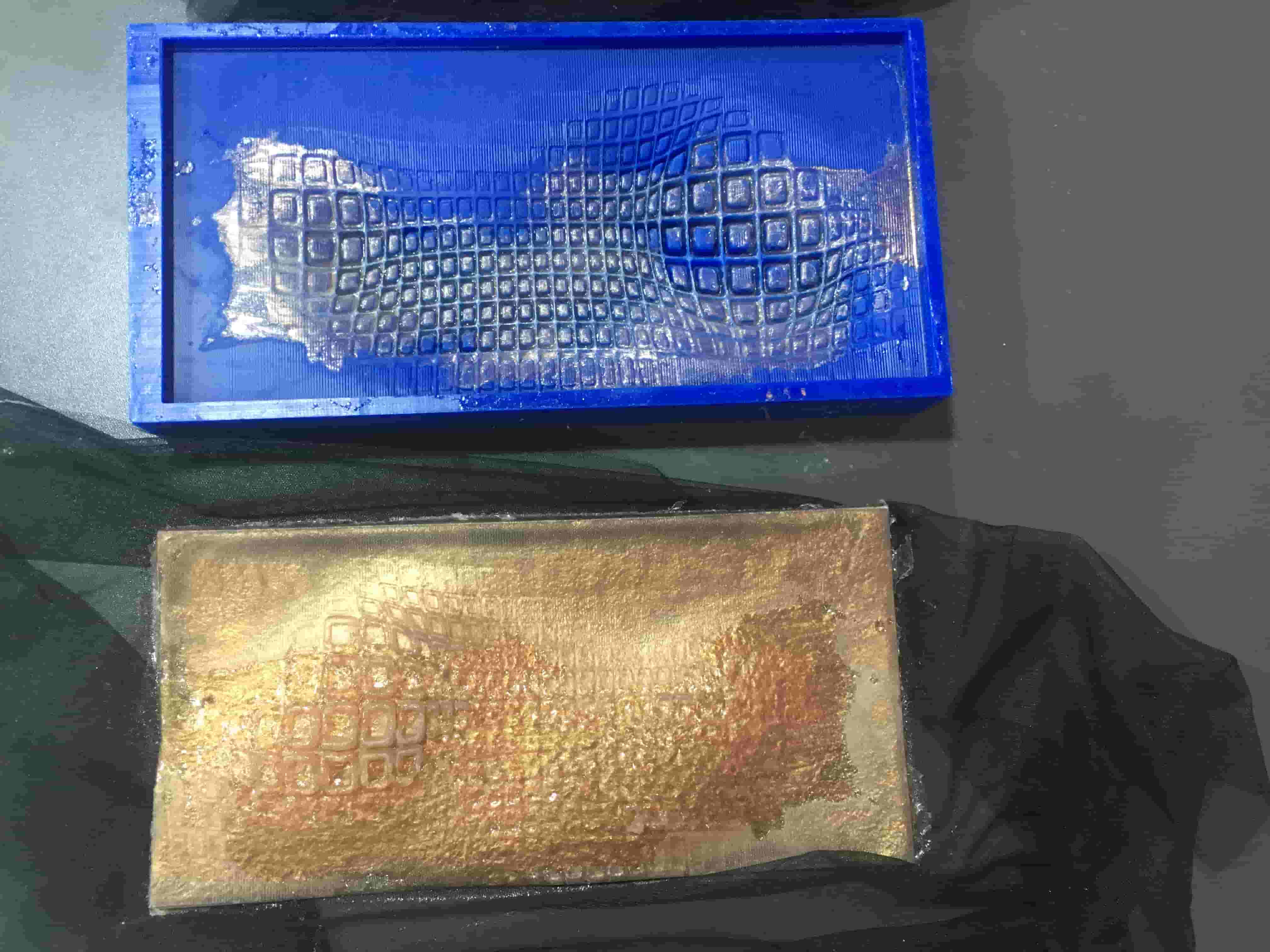
After that i tried cleaning the mold but never was actually purely clean (i tried alcohol, soap, sponge, brushes, soaking it in water and leaving it, air pressure, water pressure) to remove sticky undried silicone in the narrow fine details but either they would break the wax parts/walls between the geometries aka ruining the mold or simply wont work if im softer.
To sum up, I decided to do another design ( smaller, less detailed so nothing would stick) and make sure not to add ANYTHING to silicone. As well as not putting LOT of oil or releasing agent (as i sued to think the more the merrier and it wont stick like this … until it didn’t even dry to stick LOL)
this simple silicone on fabric with servo failed trial enhanced my decision of using 3D printed pattern of spikes on fabric for the final project for better movement
Spikes
to be continued … week 13 - Interface and Application Programming
Step3: Open attractor point- spikes from week 3/ Computer Aided design
Step 4 : Open Arduino app
Step 5 : Go to file - Sketchbook - choose (firefly firmata).
Step 6 : Then press on Upload button the get the code ready for the next step.
Step 7 : change the last part of the code as following ” only if the Arduino version is the latest version “
This way made sure my project should incorporate 2D and 3D design, additive and subtractive fabrication processes, electronics design and production, embedded microcontroller interfacing and programming, system integration and packaging
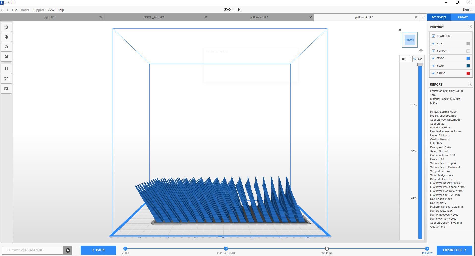
I have wanted to experiment printing on fabric trying to get as much as possible of the spikes effect as a result testing 1-Machine limitations in terms of the minimum thickness it can provide on the peak of the spike in proportion to the Nozel Size 2-material limitation in terms of using PLA vs. Flexi
Firstly I started with testing diameter size of the prints to check the quality of each…

PLA
Flexi / TPU
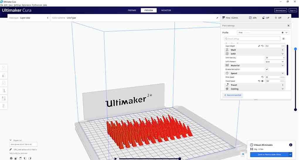
Further more wanted to test printing varying inclinations of the spikes without support material
step1: vector - grid -square grid
srep2: define a size using a number slider and connecting it to the size
step3: add another 2 number sliders and connect them to “extent Y” and “extent X”
step4: flatten cells (with right click on cells)
step5: define a point attractor … type in grasshopper “point”
step6: surface - free from - extrude point
step7: connect cells to base (in extrude point)
step8: surface - area tool (to extract the centroid) then write “move” (to move points up) and write “unit Z” and give it a number slider”
step9: vector- vector 2pt (take geometry from “move” and plug it in “vector 2pt” as point A ) not write/connect point on grasshopper and connect it in “vector 2pt” as point B
step10 : right click on unitize on “vector 2pt” - right click set Boolen - True (it means that the vector is one length- so just giving me a direction to the point attractor )
step11:
PLA on fabric
Slicing on “Cura” Software & Modifying the G code to stop at layer 2 in order to put the fabric
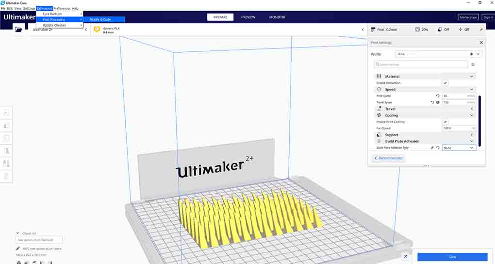 Here I played with the G-code so I can Print on Fabric: Extensions - Post Processing - Modify G-Code
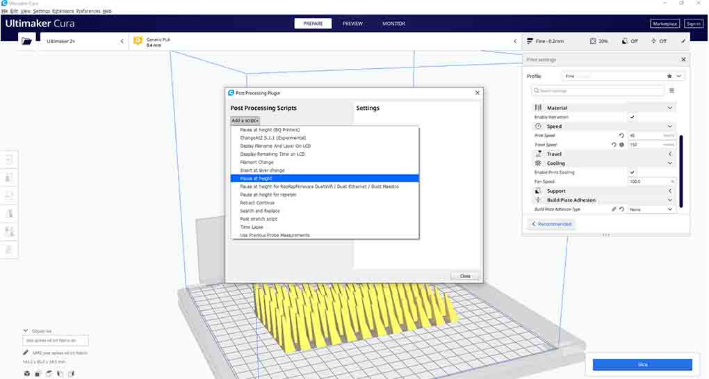 then add a script - from the drop down menu select Pause at height
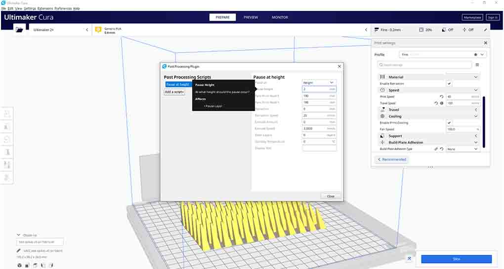 then type next to “Pause at height” the height you desire to pause on I typed “2 mm”
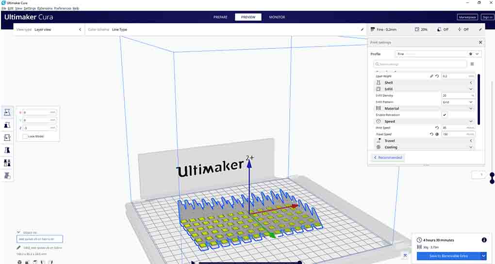 Print speed: 45 , Travel Speed: 150 (most importantly that I modified the travel speed so I wont need support for the inclinations )
 Just Checked everything then saved the G-Code to removable
Hero shot!
PLA on fabric from Batoul Al-Rashdan on Vimeo.
TPE (flexi) on fabric
after i liked it i decided to enlarge the scale
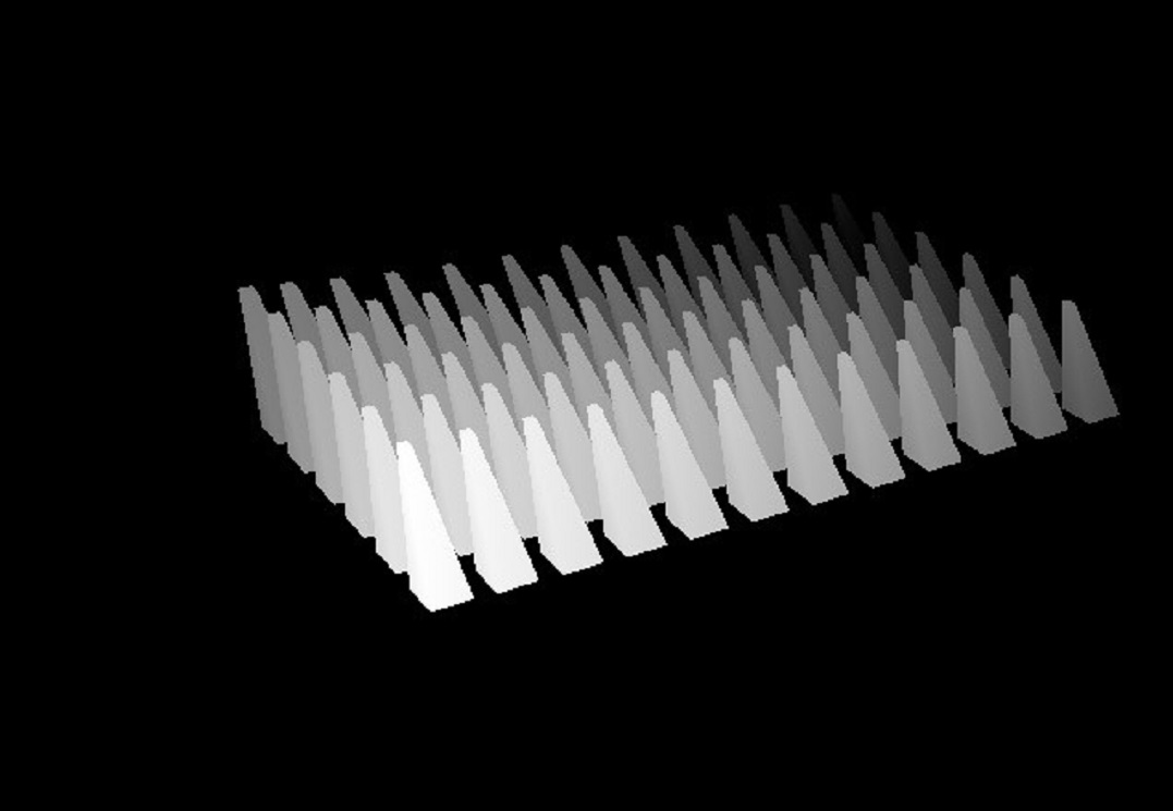
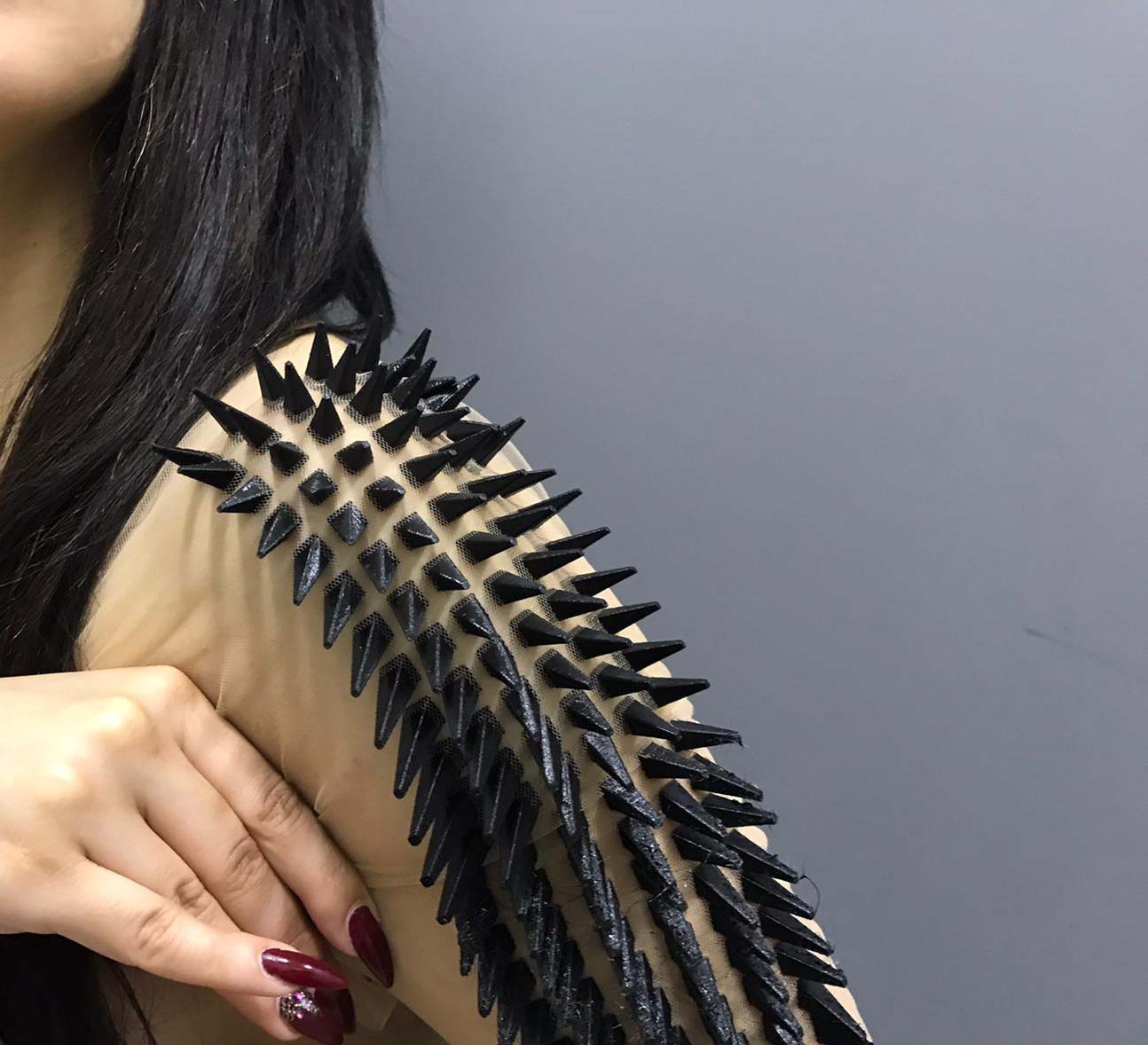
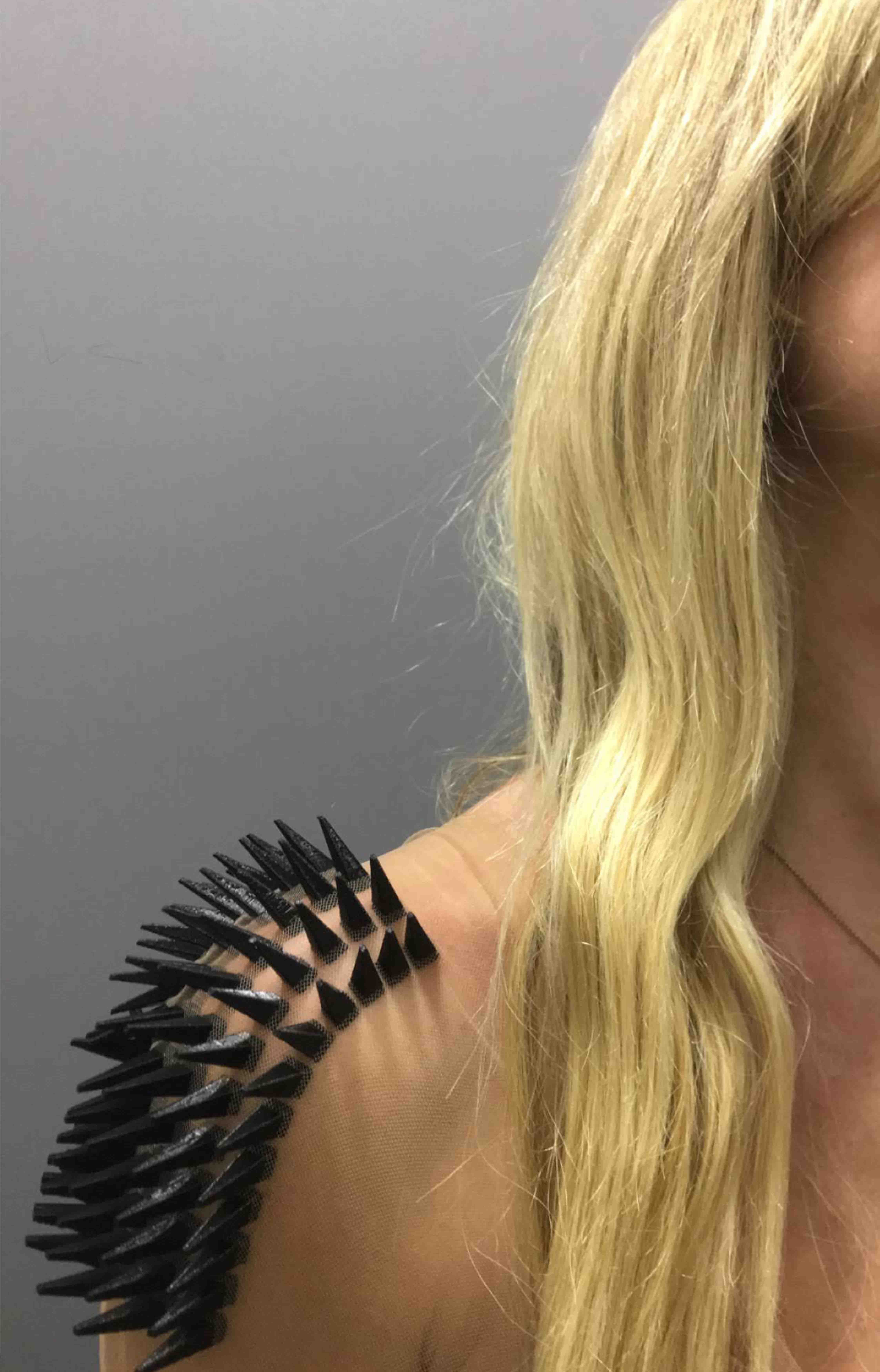
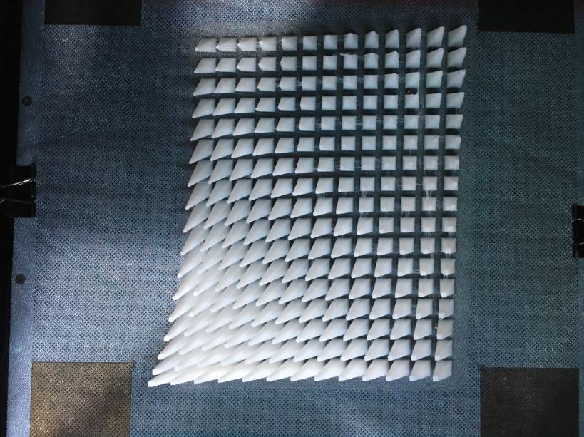
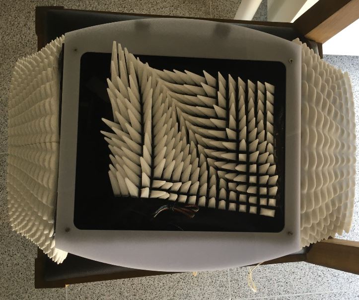
3D printed field of spikes on fabric
3D printed field of spikes on Fabric - material PLA
3D printing on fabric from Batoul Al-Rashdan on Vimeo.
Case
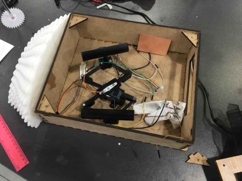
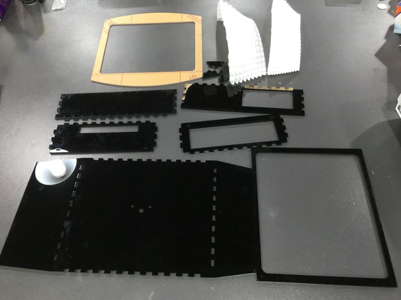
so this was my pre final Case Laser cut Acrylic with 3 3D printed sides that acts like pockets (one to keep the glove and the other to keep the power bank that responsible to give power to the project)
This is the growth of spikes I designed using grasshopper coding - function of this piece to act like a pocket … i printed 3 identical parts to be on each side of the box … so one is a pocket for the glove and one is a pocket for the power bank… and it would make it look less of a box
- Servo Holder
- Servo connection to the circuit - pinout
- Main circuit - my BOR Fabduino
- ISP from BOR Fabduino to PCP (connected/inserted in a power Bank)
- Power bank ( a cut made in the “Acrylic laser cut” box to fit the side of the power bank so I can connect the PCP to it)
- Hole left open (if i needed to fix anything with it’s on the wall)
- Bracelet + Glove pocket
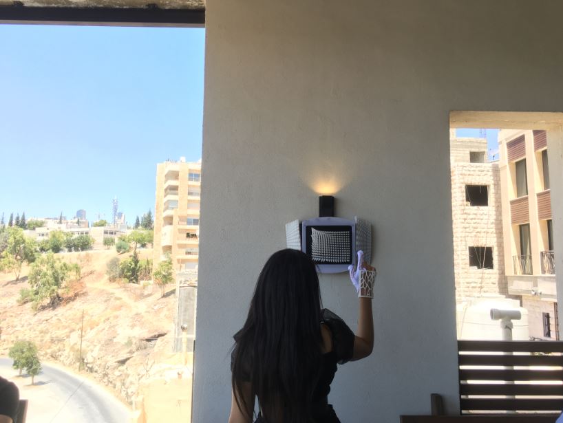
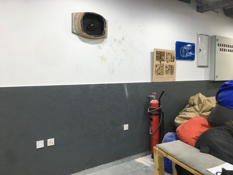
tried hanging it on wall like a real piece of art … wait its a real piece of art … this picture an “Manara” art and culture center where the directer of the cultural center thankfully removed a cliché art painting and placed my first prototype of project! yay thanks
when my initial idea had pockets like a close or so to keep the glove then i modified by doing a lil questionnaire among people around me … they claimed the glove was the most beautiful thing they have seen and they considered it art by itself and advised me not to hide it what so ever even for storage so i modified
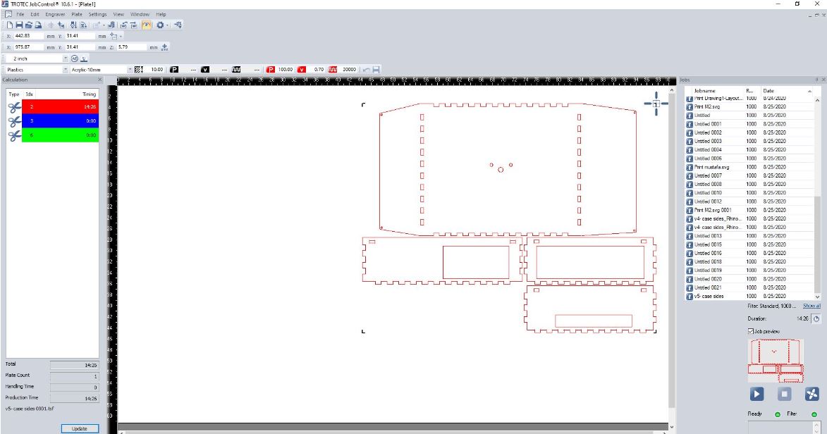
Case Design
this image contains a summary of the Case Design Development
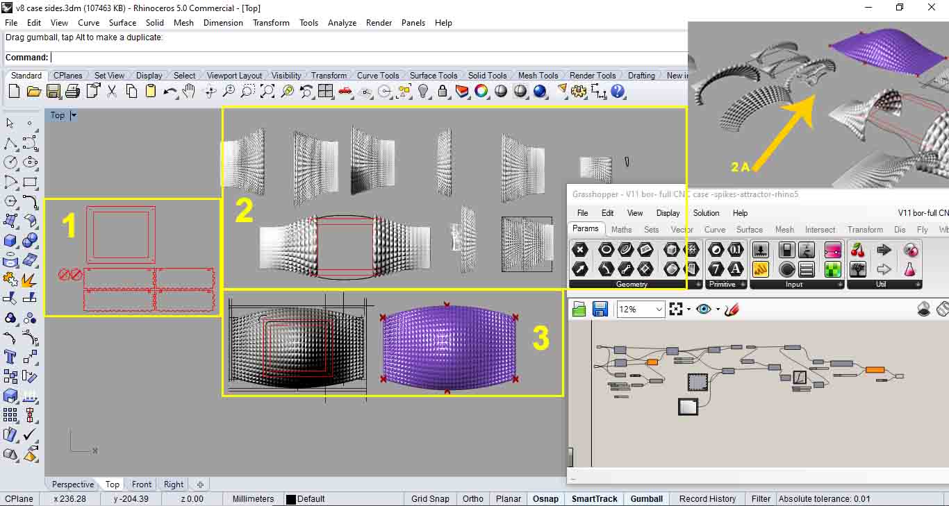
as seen in the image above: 1. First design Attempt - Laser cut 2. Second design Attempt - Laser cut + 3D printed on the sides (pockets)… so as you can see in 2A where the arrow is I’ve always made sure that the bracelet design always fitting inside the pocked of the spikes growth 3. Third design Attempt - CNC
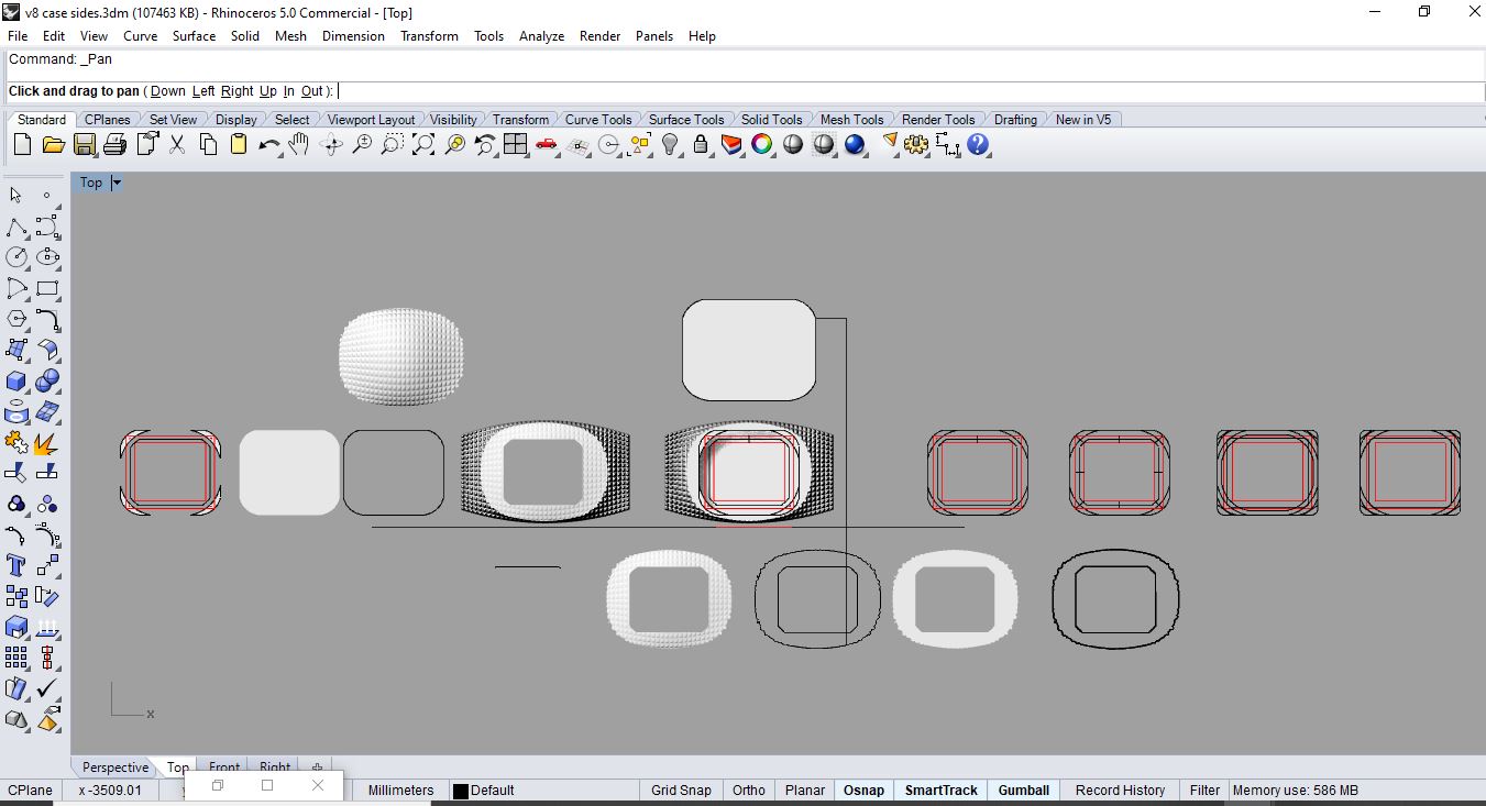 the design process of the Third design Attempt - CNC
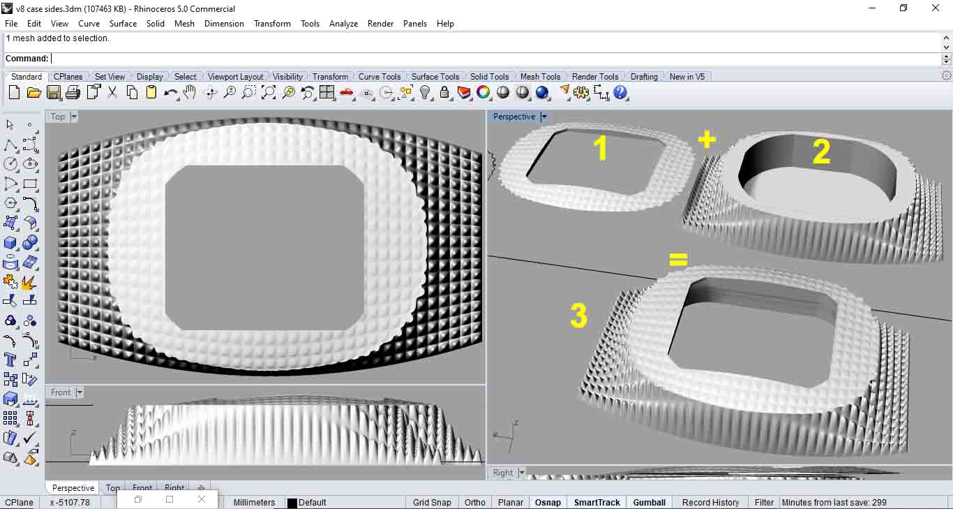 - 1 is the cover of the case
- 2 is the base of the case
- 3 os the entire case together so basically it’s 1+2
- 1 is the cover of the case
- 2 is the base of the case
- 3 os the entire case together so basically it’s 1+2
1+2 = 3
Third design Attempt - CNC final case Fabrication
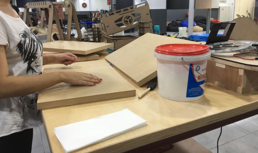
so in order to do my new growth of spikes design full case i needed to gain more wood depth and maximum MDF i could find at the lab was 4 cm thick and i needed around 10.5 cm and so … as a result i glued 4 MDFs together using wood glue and i left them over night or 2 to be extra sure …
Video making the Case
Case making from Batoul Al-Rashdan on Vimeo.
here you can after i made sure they were stuck really together … i took them to the CNC machine to cut my design … but make sure the glue is super dry otherwise the machine would go crazy while cutting your design and would be game over for the geometry and maybe the machine! (i made this case from waste MDF wood found extra in my lab as a result i collected it and layered it making a huge box with depth to cut my Case design )
Painting the Case
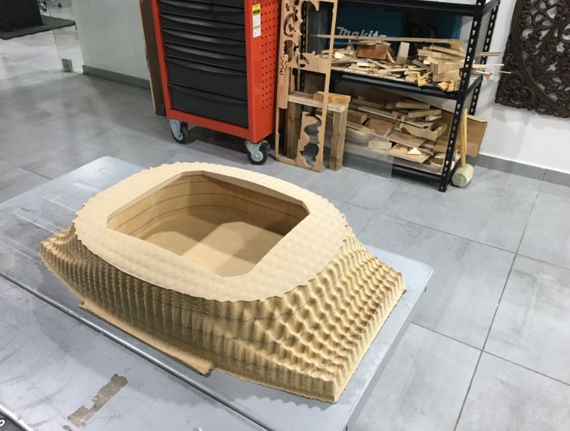 here after i finished with the CNC machine i put the cover on the case to assure how they matched exactly like i designed and i was sp happy and satisfied with the outcome… my baby turned out super great looking! very neat … especially in comparison to the horrible laser cut case that looked like a box even when i added a design for the 3D printed growth of spikes on the sides to make like a pocket for the glove and bracelet input … so this case looked more design thought of … neat as well as my friends advised me that they love the flexi sensor with the voronoi design of the bracelet and were like it’s an art piece by itself so they wanted to see it not be hidden inside a case
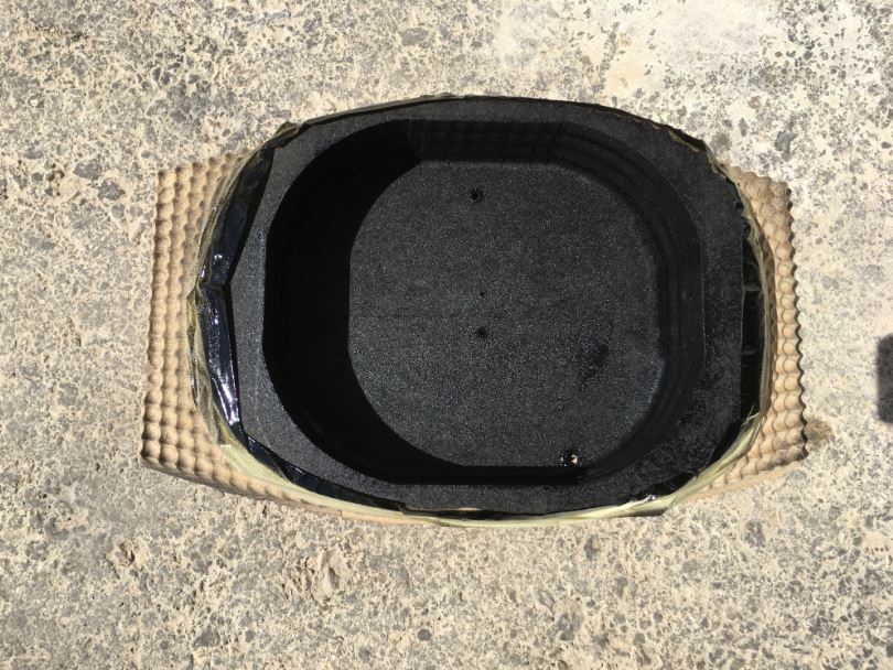 i made few opening with the drill
one opening for the stretch sensor with that long wire so i connect it to the circuit board inside the case as i didn’t want to ass the cover of the case and see inappropriate bad looking wires coming out of the case i wanted the wire attached to the flexi sensor to be coming from the back of the case
i made few opening with the drill
one opening for the stretch sensor with that long wire so i connect it to the circuit board inside the case as i didn’t want to ass the cover of the case and see inappropriate bad looking wires coming out of the case i wanted the wire attached to the flexi sensor to be coming from the back of the case
 in this picture i was hanging the case on the wall for any calibration needed and to check that opening are in correct position and if it’s holding itself … i was just testing it before adding it’s cover as well as adding the 3D print fabric
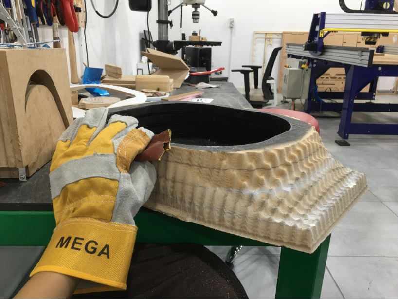 and this picture did few more extra smoothing for the surface cuz i rushed the CNC and didn’t want
Finalizing Packaging from Batoul Al-Rashdan on Vimeo.
Entire Integration
Cable connection
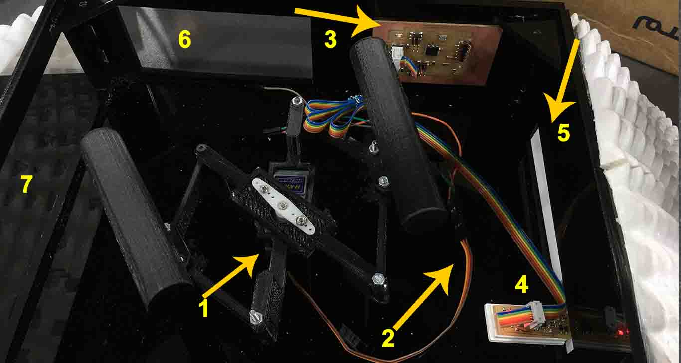
Below shown the integration of all the parts mechanical, electronics and power:
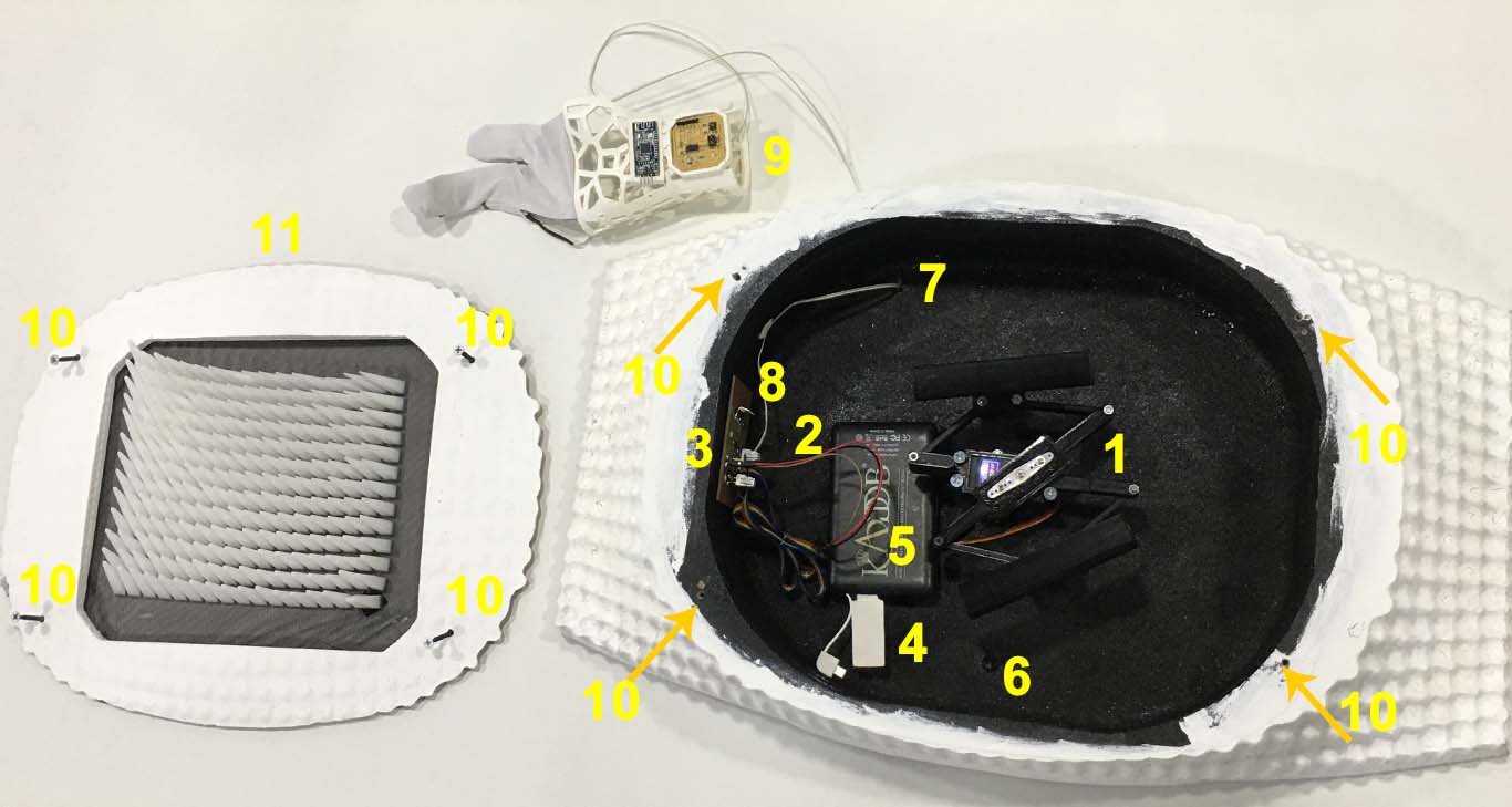
- Servo Holder and mechanical parts
- Servo connection to the circuit - pinout
- Main circuit - my BOR Fabduino
- ISP from BOR Fabduino to PCP (connected/inserted in a power Bank)
- Power bank
- Hole to hang on the wall
- Hole for connect the input flexi/stretch sensor to the main board by cable
- the cable connecting input (wire connection from the Pin to the sensor)
- flex sensor + 3D printed bracelet connected by wire to the circuit
- Cover connection to the case using 4 screws and 4 holes via drill
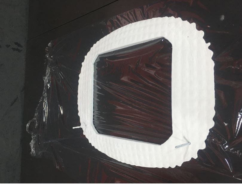
- Cover Wood made with CNC and painted white attached to it the 3D print on fabric
more details regarding 11 shown below:
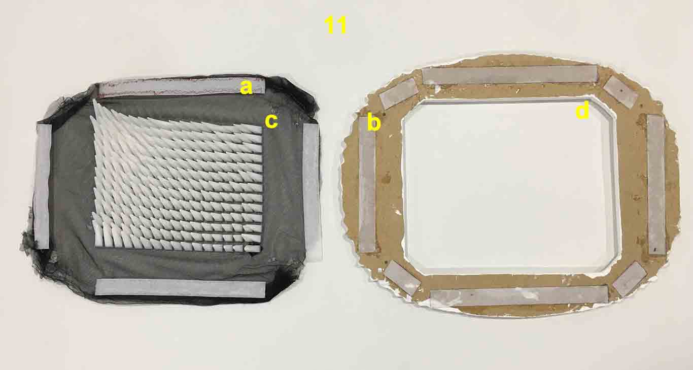 11. Cover Wood made with CNC and painted white attached to it the 3D print on fabric
- a = Positive part of Velcro / Hook-and-loop fasteners, hook-and-pile fasteners or touch fasteners
- b = Negative part of Velcro / Hook-and-loop fasteners, hook-and-pile fasteners or touch fasteners
-
c = The 3D print on fabric
-
d = Open on the CNC cut cover dimension made to fit the dimension of the spikes field to move smoothly without knocking the cover or disturb the movements
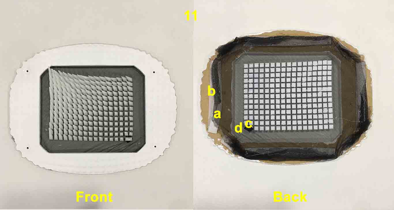 11. Cover Wood made with CNC and painted white attached to it the 3D print on fabric
- here is shown that (a + b) are ATTACHED
11. Cover Wood made with CNC and painted white attached to it the 3D print on fabric
- here is shown that (a + b) are ATTACHED
- a = Positive part of Velcro / Hook-and-loop fasteners, hook-and-pile fasteners or touch fasteners]
-
b = Negative part of Velcro / Hook-and-loop fasteners, hook-and-pile fasteners or touch fasteners
-
c = The 3D print on fabric
-
d = Open on the CNC cut cover dimension made to fit the dimension of the spikes field to move smoothly without knocking the cover or disturb the movements