9. Embedded programming
This week
Individual assignment: read a microcontroller data sheet program your board to do something, with as many different programming languages and programming environments as possible
Group assignment: compare the performance and development workflows for other architectures
Files to download : All the files to download:
Fuse calculator (right click on the link and “save as”)and open the html inside.
Group assignment :
Due to the corona virus crisis quarantine and curfew, there was no access the lab so the group assignment delayed until further notice, compare the performances and development work flow .
individual assignment :
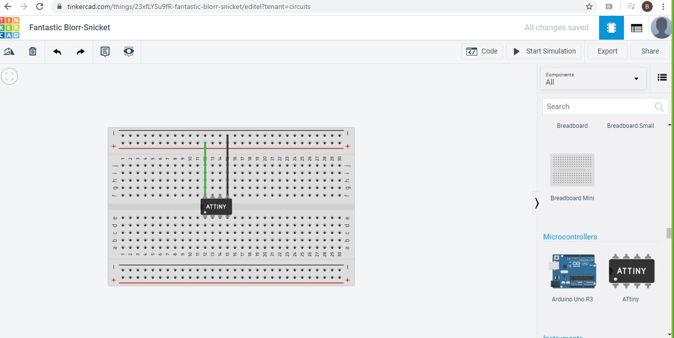
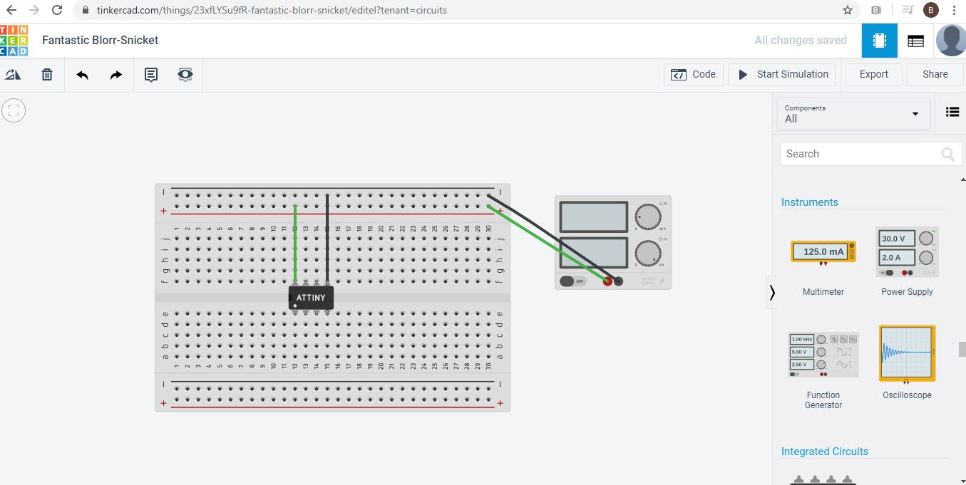
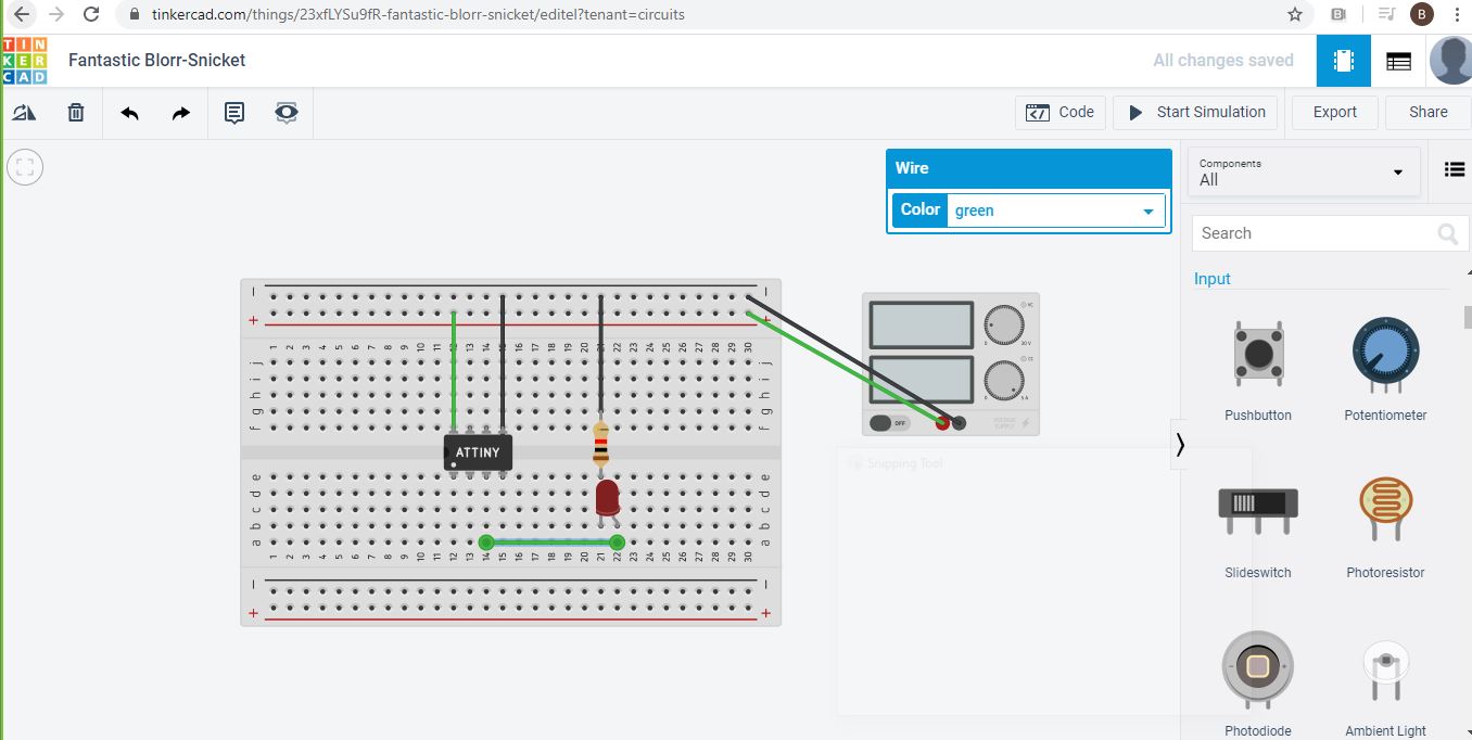
Due to the corona virus crisis quarantine and curfew as well, there was no access the lab so the i have used tinkercad to create a similar board to week 06 an try to program it until further notice.
What is the “ATtiny44” ?
I have used the “ATtiny44” as a microcontroller , So i have to read the ATtiny44 datasheet.
First what is a datasheet : Datasheets, are instruction manuals for electronic components, they explain exactly what a component does and how to use it.
The first page is usually a summary of the function and features of the component. You can quickly find a description of the functionality, the basic specifications (numbers that describe what a component needs/can do and sometimes a functional block diagram that shows the internal functions).
Pinout lists the component’s pins, their functions, and where they’re physically located on the component.
Pin configurations And Pin descriptions : Here you can see the Pin configurations and the Pin descriptions of the ATtiny44 :
Code
getting familiar with coding
void setup() {
// initialize digital pin 2 (PA2) as an output referring to the ATtiny44 datasheet .
pinMode(2, OUTPUT);
}

// the loop function runs over and over again forever
void loop() {
digitalWrite(2, HIGH);
delay(10);
digitalWrite(2, LOW);
delay(10);
}
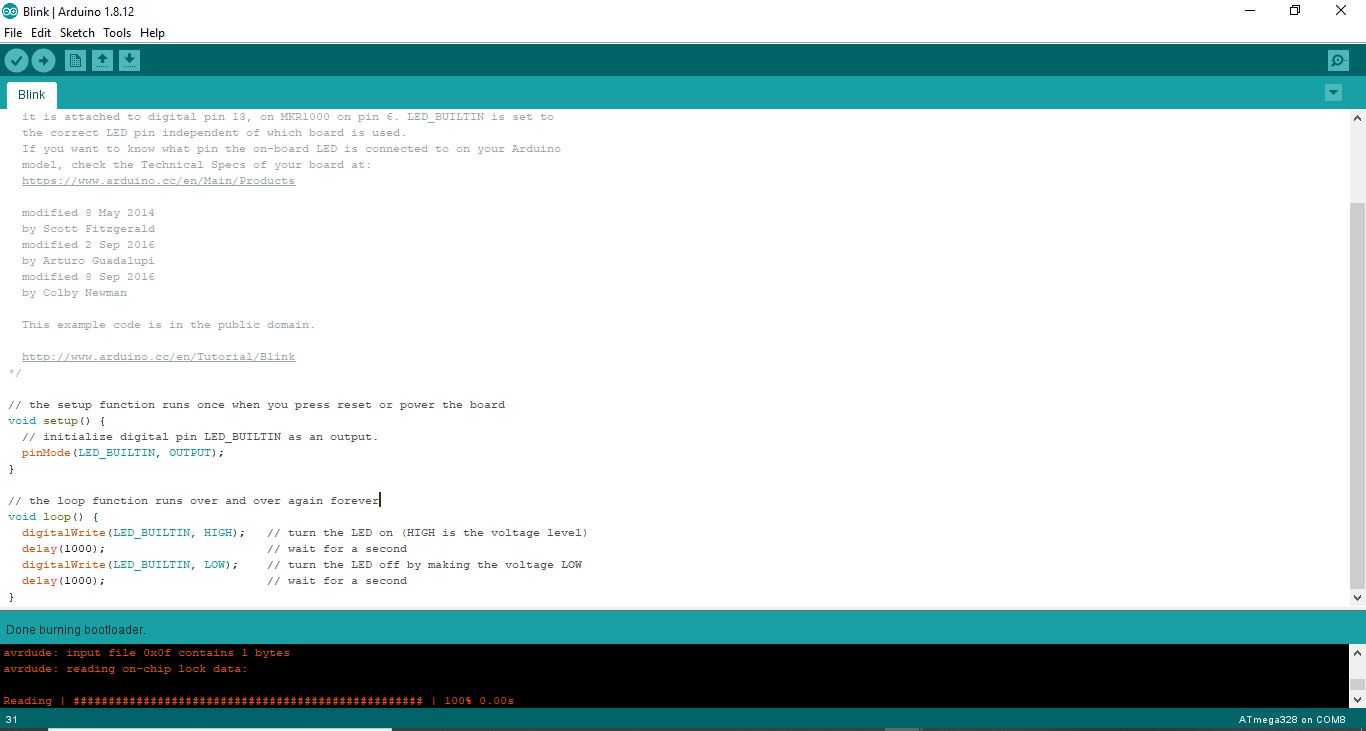
One LED circuit
Turns an LED on for one second, then off for one second, repeatedly.

 Most Arduinos have an on-board LED you can control. On the UNO, MEGA and ZERO
 it is attached to digital pin 13, on MKR1000 on pin 6. LED_BUILTIN is set to
 the correct LED pin independent of which board is used.
 If you want to know what pin the on-board LED is connected to on your Arduino
 model, check the Technical Specs of your board at:
 https://www.arduino.cc/en/Main/Products

 modified 8 May 2014
 by Scott Fitzgerald
 modified 2 Sep 2016
 by Arturo Guadalupi
 modified 8 Sep 2016
 by Colby Newman

 This example code is in the public domain.

 http://www.arduino.cc/en/Tutorial/Blink
*/

// the setup function runs once when you press reset or power the board
void setup() {
 // initialize digital pin LED_BUILTIN as an output.
 pinMode(12, OUTPUT); // which pin
}

// the loop function runs over and over again forever
void loop() {
 digitalWrite(12, HIGH);   // turn the LED on (HIGH is the voltage level)
 delay(1000);                       // wait for a second
 digitalWrite(12, LOW);    // turn the LED off by making the voltage LOW
 delay(1000);                       // wait for a second
}
PIR with LED
int LED = 12;             // the pin that the LED is atteched to
int PIR = 7;              // the pin that the sensor is atteched to

void setup() {
  pinMode(LED, OUTPUT);   // initalize LED as an output
  pinMode(PIR, INPUT);    // initialize sensor as an input
  Serial.begin(9600);     // initialize serial
}

void loop(){
  if (digitalRead(PIR) == HIGH) { // check if the sensor is HIGH
    digitalWrite(LED, HIGH);      // turn LED ON
    Serial.println("Motion detected!");
    delay(1000);                   // delay 100 milliseconds
  }
  else {
    digitalWrite(LED, LOW);       // turn LED OFF
    Serial.println("Motion stopped!");
    delay(1000);                   // delay 100 milliseconds
  }
}
Programming
To program my boards from my laptop (windows) download drivers and tools:
Downloading Arduino IDE: For me i used “Arduino IDE” and you can download it by Clicking here.
Adding the Atmega238 library After successfully downloading “Arduino IDE” downloaded the “Atmega238 library”
opened Arduino IDE and go to Files>> Preferences, And this window will appear
Copied json link for the ATMega238 and paste it in “Additional board manager URLs”
Now Tools >> Boards >> Board manager
type “Atmega238“ and click on install
Downloading “tools” and “Drivers”
1-Downloaded toolchain for windows after successfully downloading the zip file, extract the file on {C/ Program files} if it didnt work which happened with me and kept giving you errors just extract the file on your desktop and cut it then paste it on {C/ Program files} .
2-GNU Make and to do that just Click here when you successfully download it just open it and accept the default location for the installation(dont repeat my mistake and remember where the hell you saved it)
3-Download Avrdude and then extract the file on {C/ Program files} and if it didnt work just again use your magical “save on desktop weapon” and cut it then paste it on {C/ Program files}.
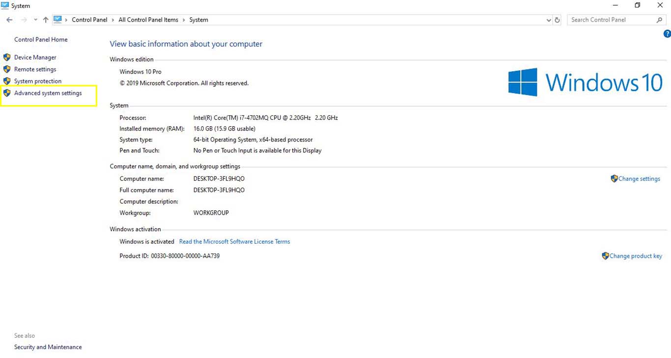
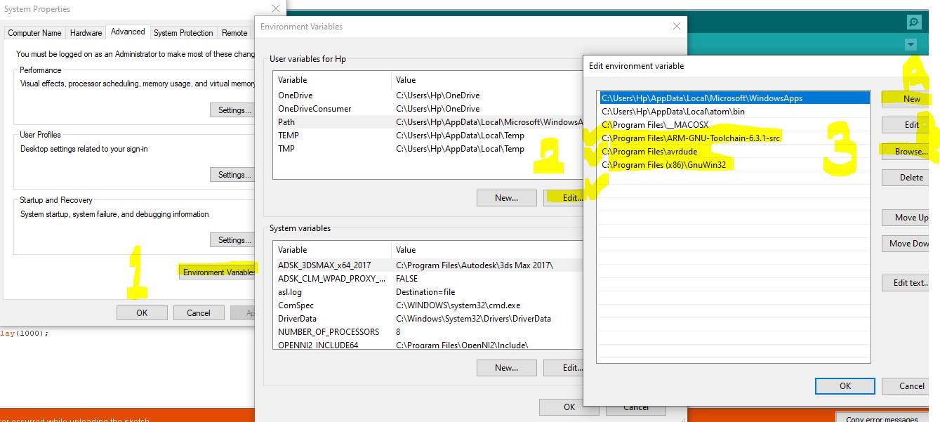
4- Update path, in order to inform Windows where to locate all of the tools you’ve just installed.
and to do that from Start menu and open the Control Panel, then go to System. From the left pane, choose “Advanced System Settings”. Under the Advanced tab, click the “Environment Variables” button
Downloaded drivers for the Programmer and go to Options >> List All Devices then Select “USBtinySPI” from the dropdown list and select “libusb-win32 (v1.2.6.0)” in the target driver side then Click on “Install Driver”

so as you can see here it had been PROGRAMMED FINALLY