9. Future Improvements
Bluetooth
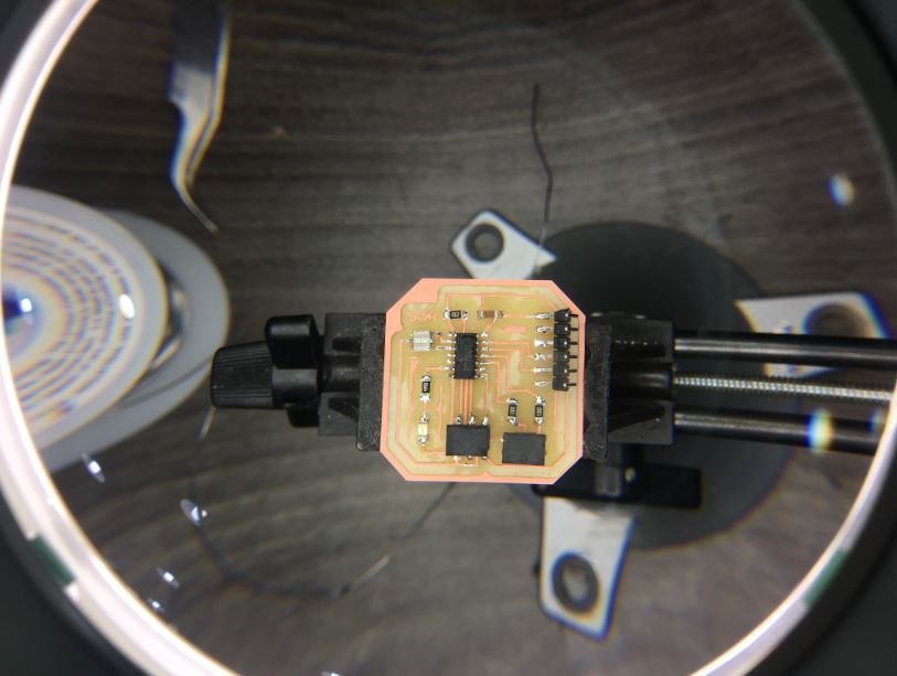
in the bracelet design I managed to create voids in it to insert Bluetooth and input board that I made as seen below
I will use the board created for input to link via Bluetooth to the main board
Bracelet
Design
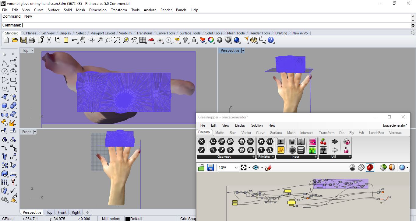
This voronoi bracelet designed to grew on my 3D hand scan as a result fitting my real hand with spaces to put Bluetooth as well as input board for future Plan to connect stretch-flexi sensor with the output(servo moving spikes) via Bluetooth and stop seeing the wire … I wanted to prepare the design for such step from early stages as a designer I enjoy designing
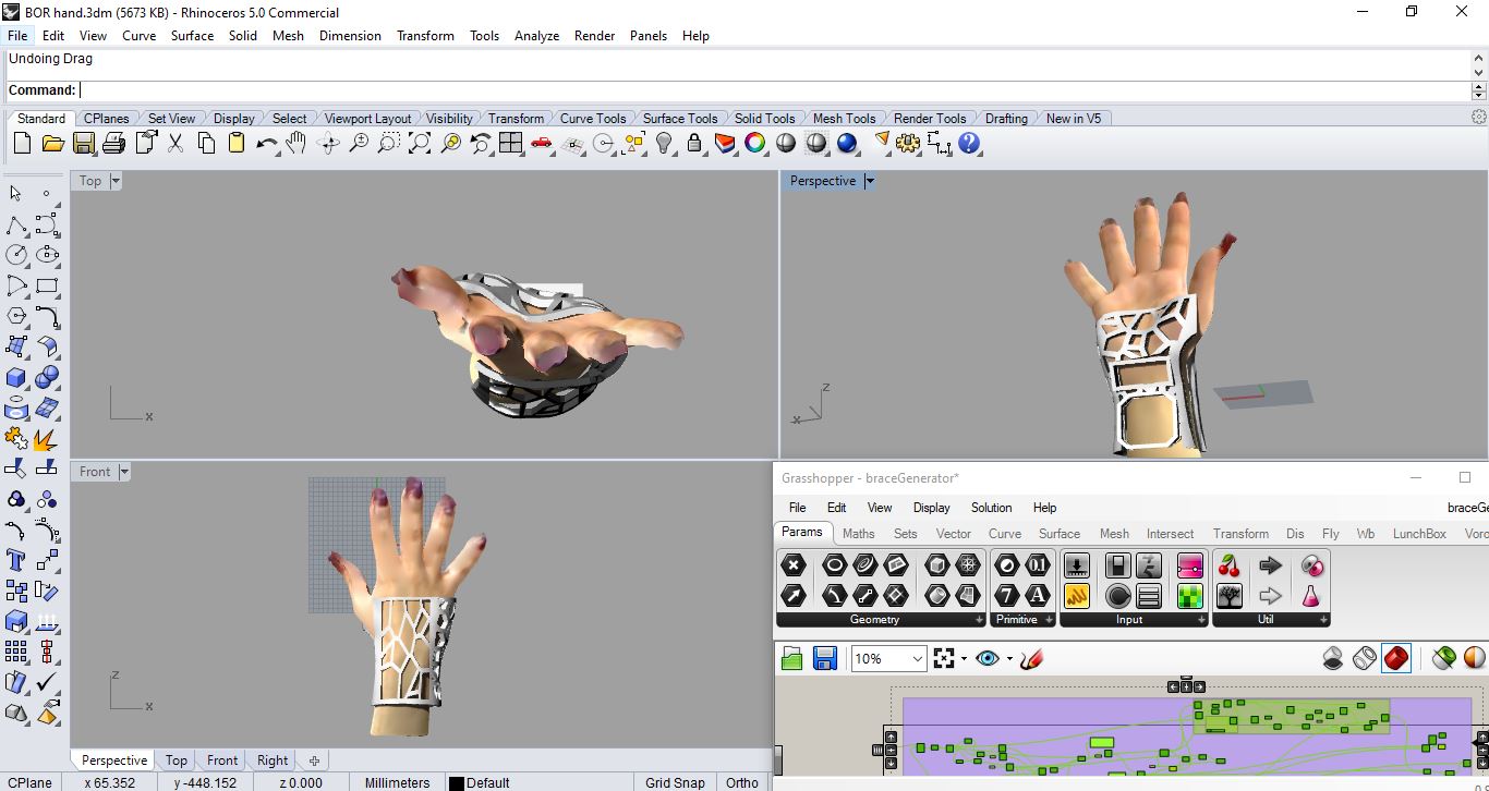 here the finished outcome of the voroni bracelet on my hand where it support and has empty spots fit exactly to my inpout board and Bluetooth for future reference of connecting my final project via bluetooth not wires anymore cool no? and it’s an exact fit to my hand and ready to print
Fabrication
Input - Bluetooth Board
BOR stretch sensor board design.
BOR Schematic design
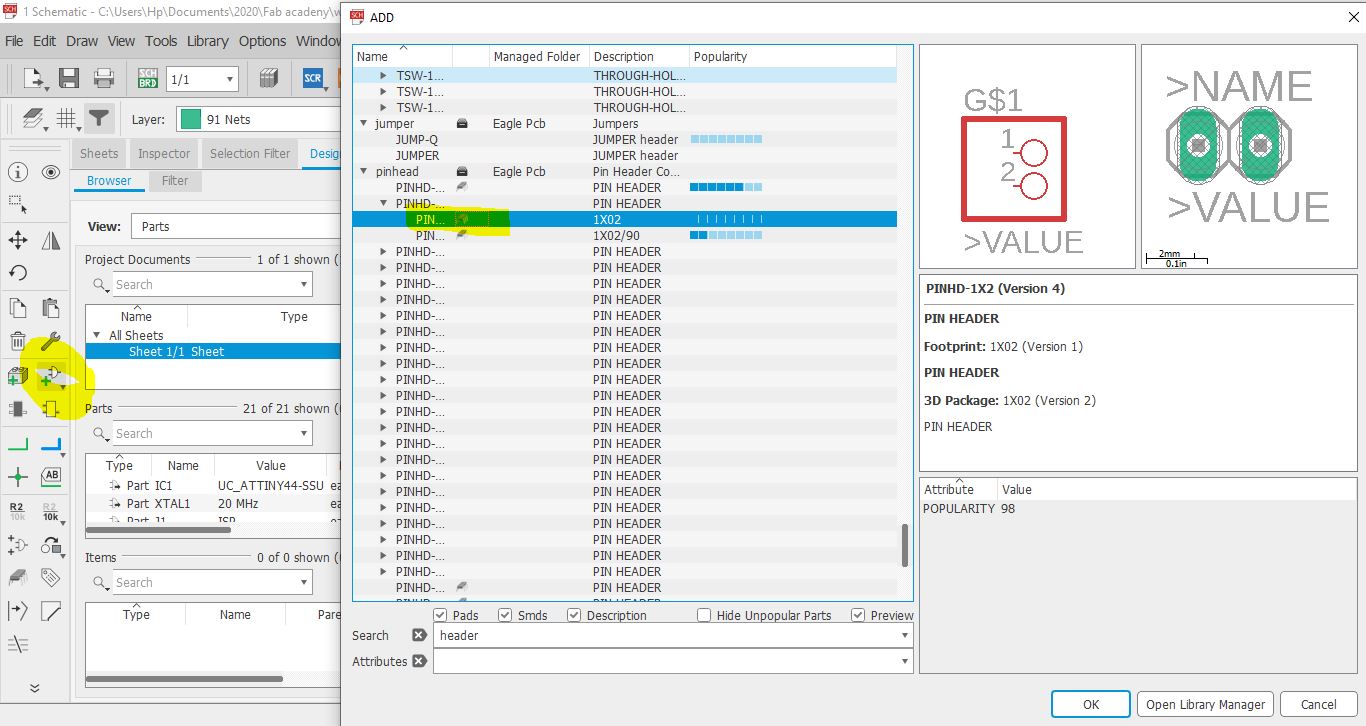 so remember the board i design Week07.I open it’s schematic design on eagle and replaced the Button with a pinhead 1*02 (from add part)so i can connect the stretch sensor to it.
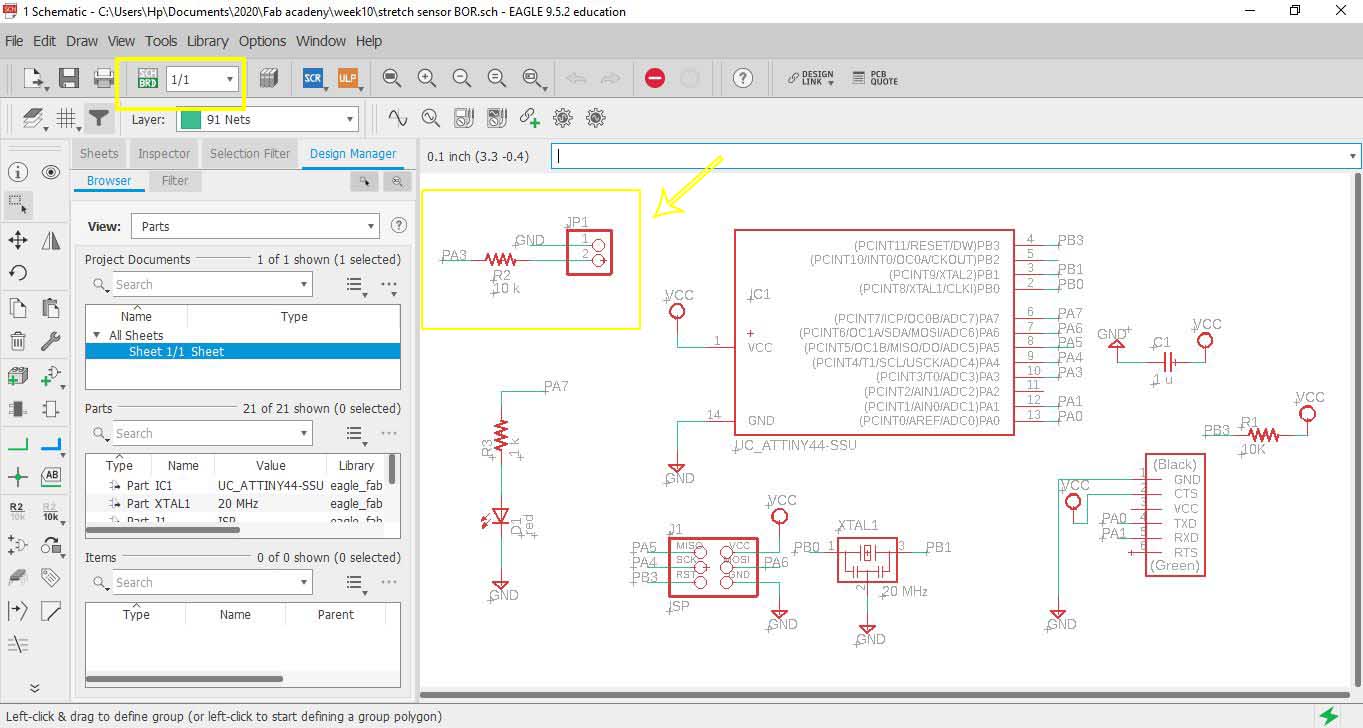 then connected the Pin head 1- to GND and 2- to resistor and one of pins of ATTiny in this PA3
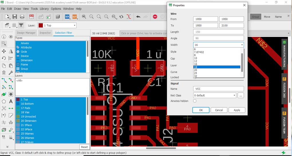 i thought of changing the wire width since during Week07 I got a short circuit and I had to scratch a part that mods didn’t read and the machine didn’t cut by hand a cutter so changed wire width from 16 to 18 BUTTTTTTT
 first I got more errors regarding the spacing! but the main problem is I misunderstood this … increasing wire width would create more problems! instead I should be changing the spaces between wires AKA the “clearance”
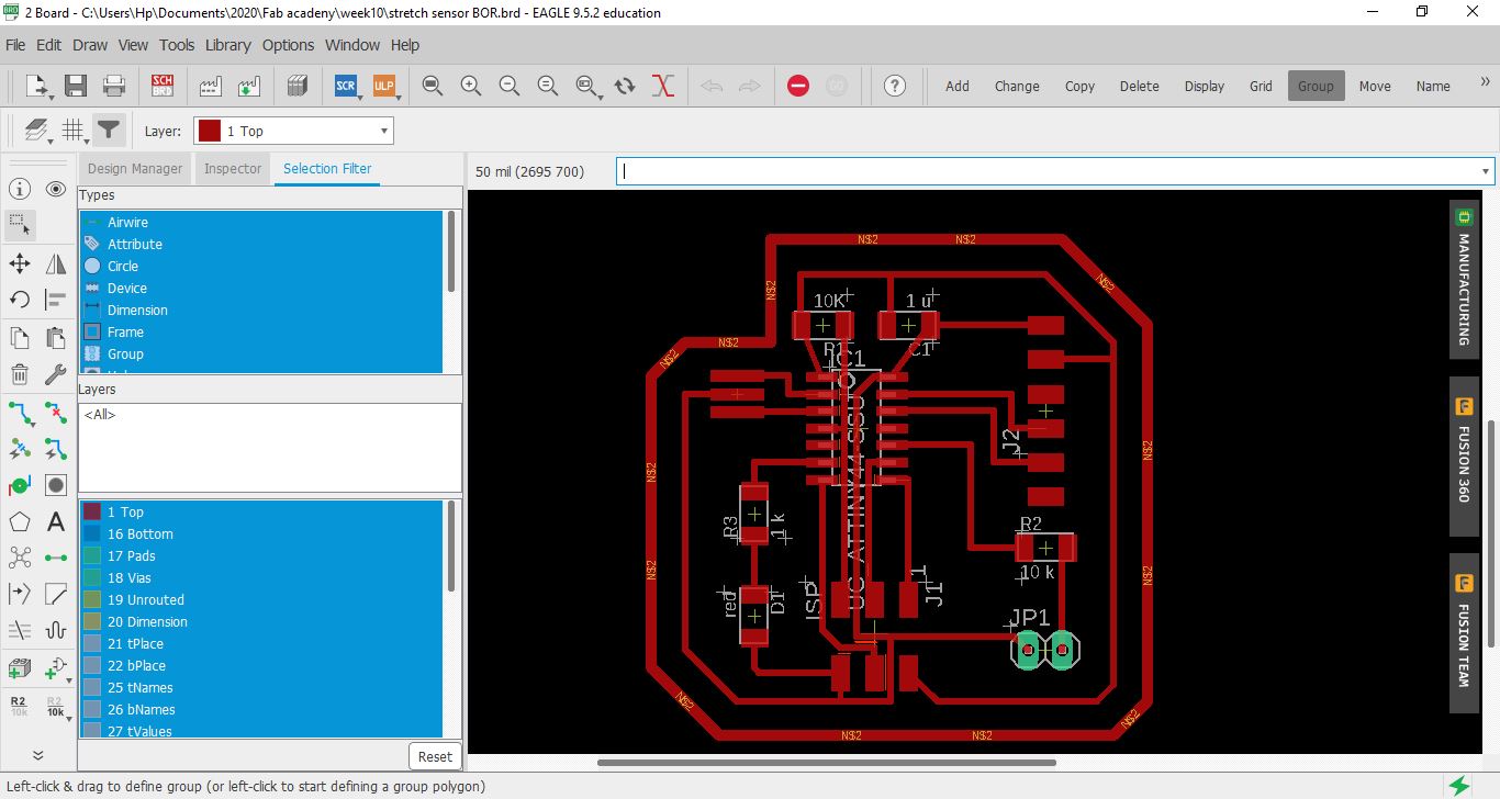
 so like a really good girl went back to and changed all wires to from 18 to 14 (even less wire width as it shall be better)
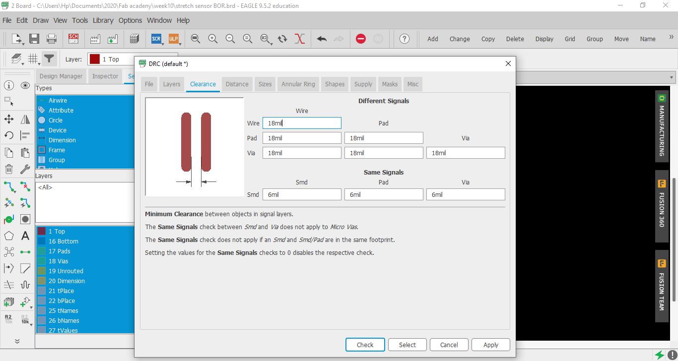 changed the clearance from DRC (bottom left) all to 18mil.
but guess what?
yup got more and more errors yay
changed the clearance from DRC (bottom left) all to 18mil.
but guess what?
yup got more and more errors yay
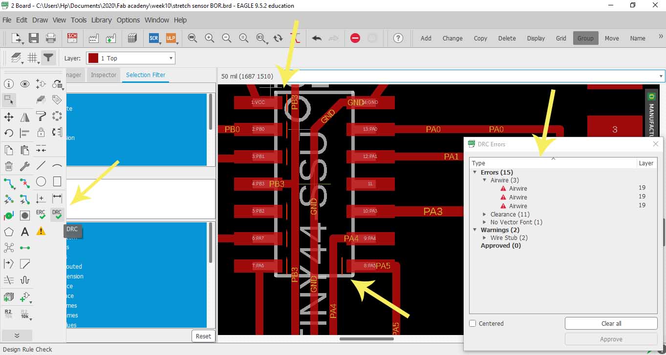 Wonderful! I was scared I’ll have to re-route but nahhh, not today!
Bill Gates was right, once said “I choose a lazy person to do a hard job. Because a lazy person will find an easy way to do it.” Yup ladies and Gentlemen I AM THAT LAZY PERSON so here is what I did…
Wonderful! I was scared I’ll have to re-route but nahhh, not today!
Bill Gates was right, once said “I choose a lazy person to do a hard job. Because a lazy person will find an easy way to do it.” Yup ladies and Gentlemen I AM THAT LAZY PERSON so here is what I did…
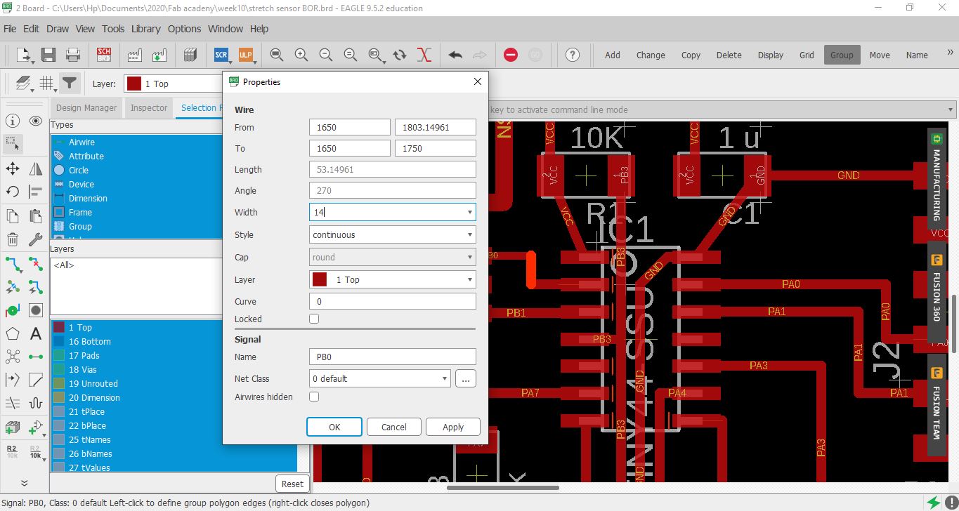
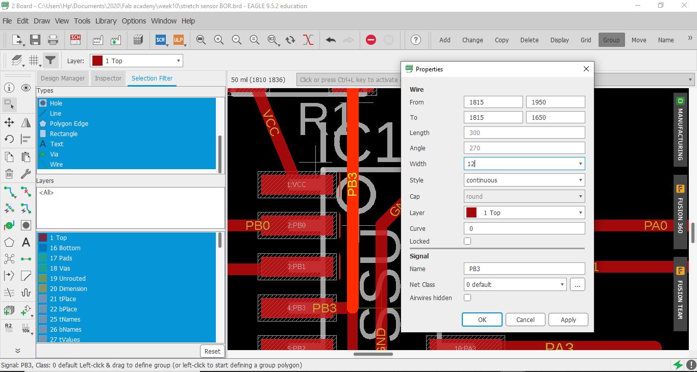 wherever I saw an error, just changed the wire next to them from 14 to 12(wire width by right clicking - properties - width - 12 )
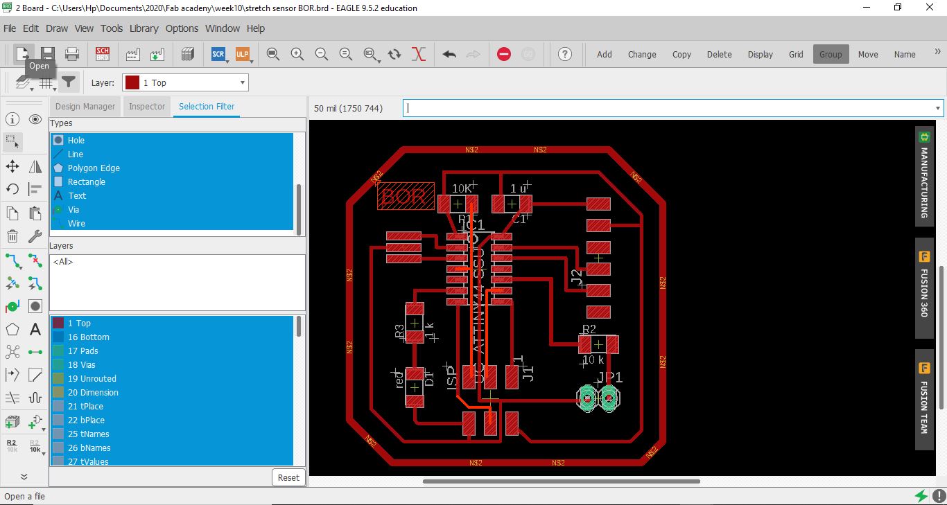 so I ended up only changing the wire width of these highlighted wires and no errors anymore … aka “bbye re-routing”
so as you can see here ive used FTDI to read the signal and pin A0 and A1 for the analogue signal
Code Example
I still need to link to Bluetooth
Use the three backticks to separate code.
/*
  ReadAnalogVoltage

  Reads an analog input on pin 0, converts it to voltage, and prints the result to the Serial Monitor.
  Graphical representation is available using Serial Plotter (Tools > Serial Plotter menu).
  Attach the center pin of a potentiometer to pin A0, and the outside pins to +5V and ground.

  This example code is in the public domain.

  http://www.arduino.cc/en/Tutorial/ReadAnalogVoltage
*/

// the setup routine runs once when you press reset:
void setup() {
  // initialize serial communication at 9600 bits per second:
  Serial.begin(9600);
}

// the loop routine runs over and over again forever:
void loop() {
  // read the input on analog pin 0:
  int sensorValue = analogRead(A0);
  delay(500);
  // Convert the analog reading (which goes from 0 - 1023) to a voltage (0 - 5V):
  float voltage = sensorValue * (5.0 / 1023.0);
  // print out the value you read:
  Serial.println(voltage);
}
Soldering