6. Input & it’s packaging
Step 1 : (http://fabacademy.org/2020/labs/techworks/students/batoul-alrashdan/assignments/week10/) I used stretch sensor after following this schematic
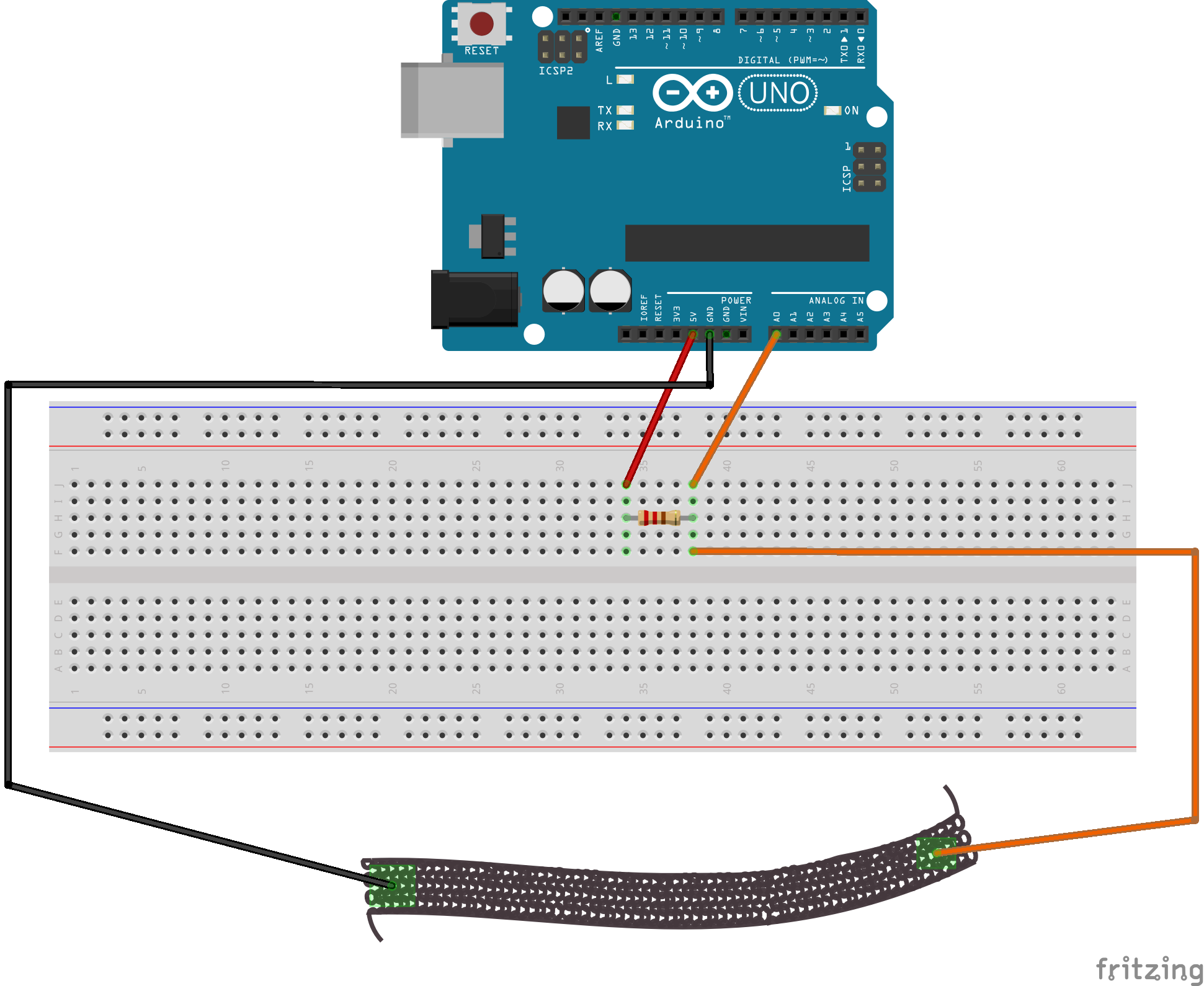
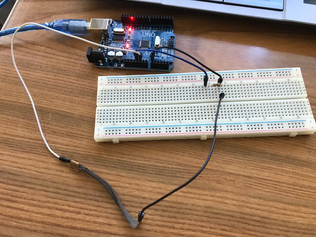
Step 2: where I got physical then connected Arduino and verified and uploaded the code
Don’t freak out Neil! this is the piece i wanted to use for final project making glove so i didnt want to cut any part from it just in case due to COVID-19 if wouldn’t be able to buy online again …
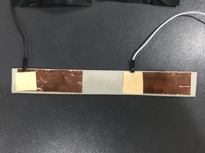
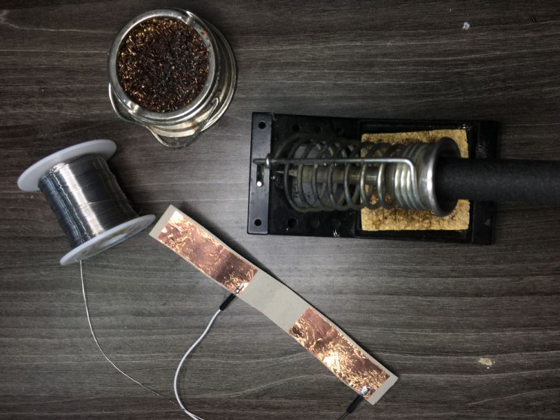
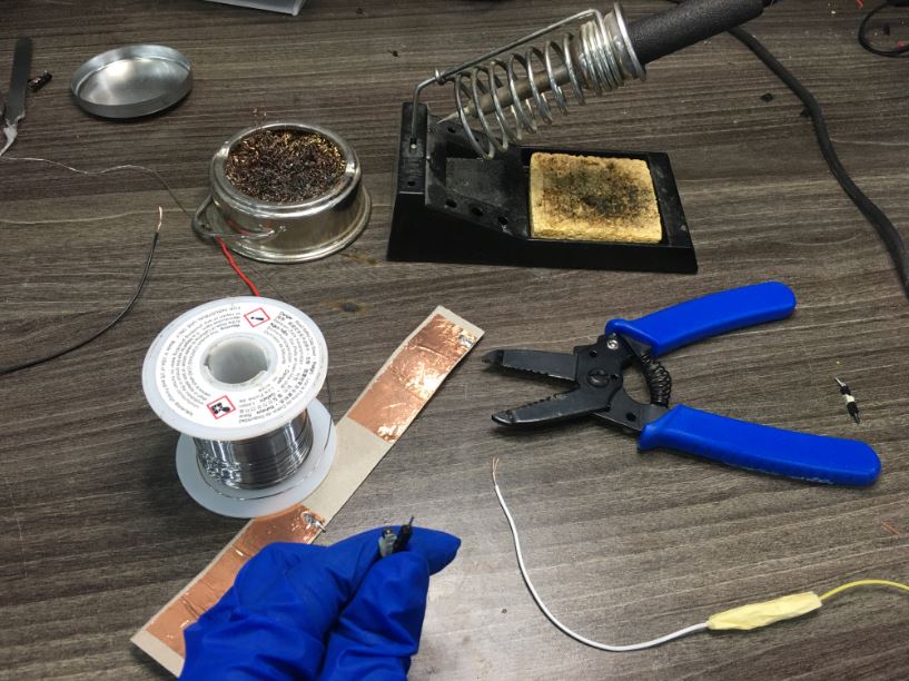
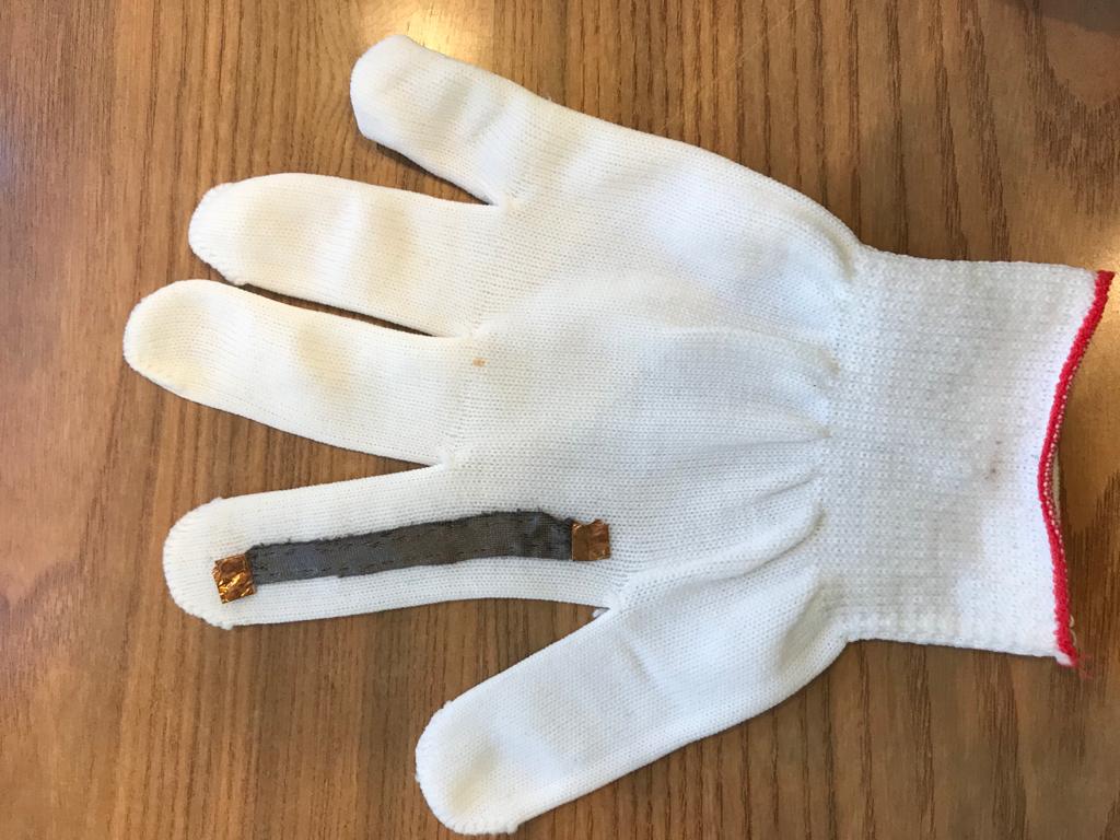 tried sewing the stretch conductive fabric to the glove as we are in a lockdown due to COVID-19 and added copper to the ends to make it easier connecting it with wires available
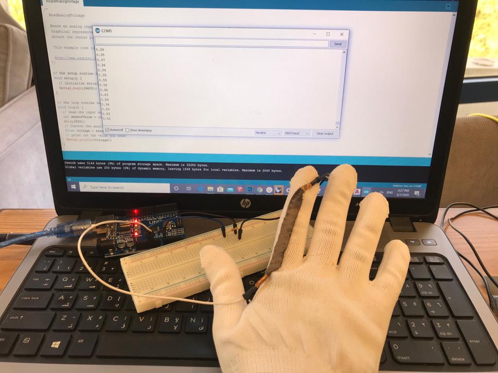
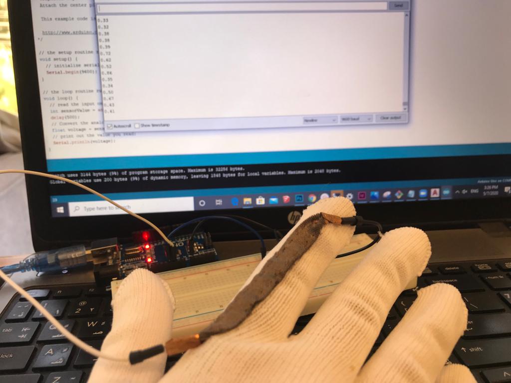 then I connected the circuit/wires to the copper attached to the conductive stretch fabric and connected arduino with ReadAnalogVoltage Code after modifying it to delay so I can be able to see the change in voltage
Code Example
Use the three backticks to separate code.
/*
  ReadAnalogVoltage

  Reads an analog input on pin 0, converts it to voltage, and prints the result to the Serial Monitor.
  Graphical representation is available using Serial Plotter (Tools > Serial Plotter menu).
  Attach the center pin of a potentiometer to pin A0, and the outside pins to +5V and ground.

  This example code is in the public domain.

  http://www.arduino.cc/en/Tutorial/ReadAnalogVoltage
*/

// the setup routine runs once when you press reset:
void setup() {
  // initialize serial communication at 9600 bits per second:
  Serial.begin(9600);
}

// the loop routine runs over and over again forever:
void loop() {
  // read the input on analog pin 0:
  int sensorValue = analogRead(A0);
  delay(500);
  // Convert the analog reading (which goes from 0 - 1023) to a voltage (0 - 5V):
  float voltage = sensorValue * (5.0 / 1023.0);
  // print out the value you read:
  Serial.println(voltage);
}
Interface and Application Programming
This week I worked on:
individual assignment: write an application that interfaces a user with an input &/or output device that I made
group assignment: compare as many tool options as possible
Files to Download
Kindly find below all the filed you need to download:
Software’s:
My Design files:
made sure you download Firefly Plugin to be able to use the grasshopper Script
I have tried with many but finally made the individual assignment with:
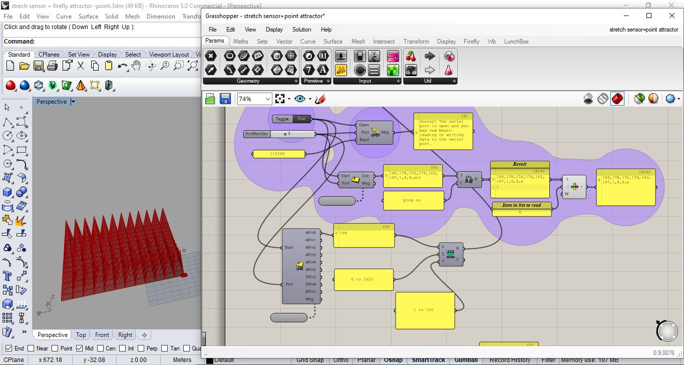
Arduino + Rhino + Grasshopper + Firefly
Tutorial
FIREFLY – SERIAL READ ULTRASONIC SENSOR
Now let’s get it Done but with stretch fabric:
Reminder from input devices week
Step 1 : from input week where I used stretch sensor
Step 2: where I got physical then connected Arduino and verified and uploaded the code
Don’t freak out Neil! this is the piece i wanted to use for final project making glove so i didnt want to cut any part from it just in case due to COVID-19 if wouldn’t be able to buy online again …
This week to be continued …
Step3: Open attractor point- spikes from week 3/ Computer Aided design Experimenting with pattern i would use on fabric for final project
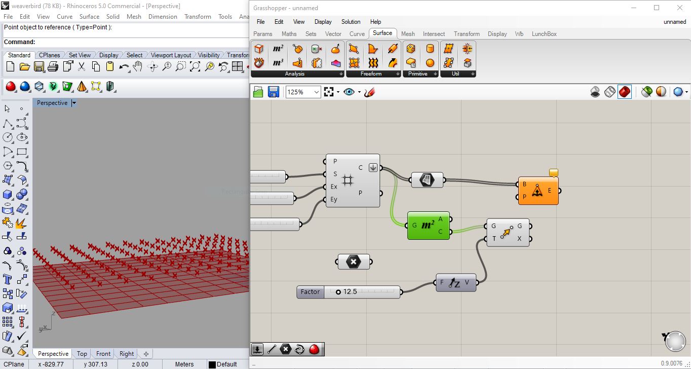 A: vector - grid -square grid
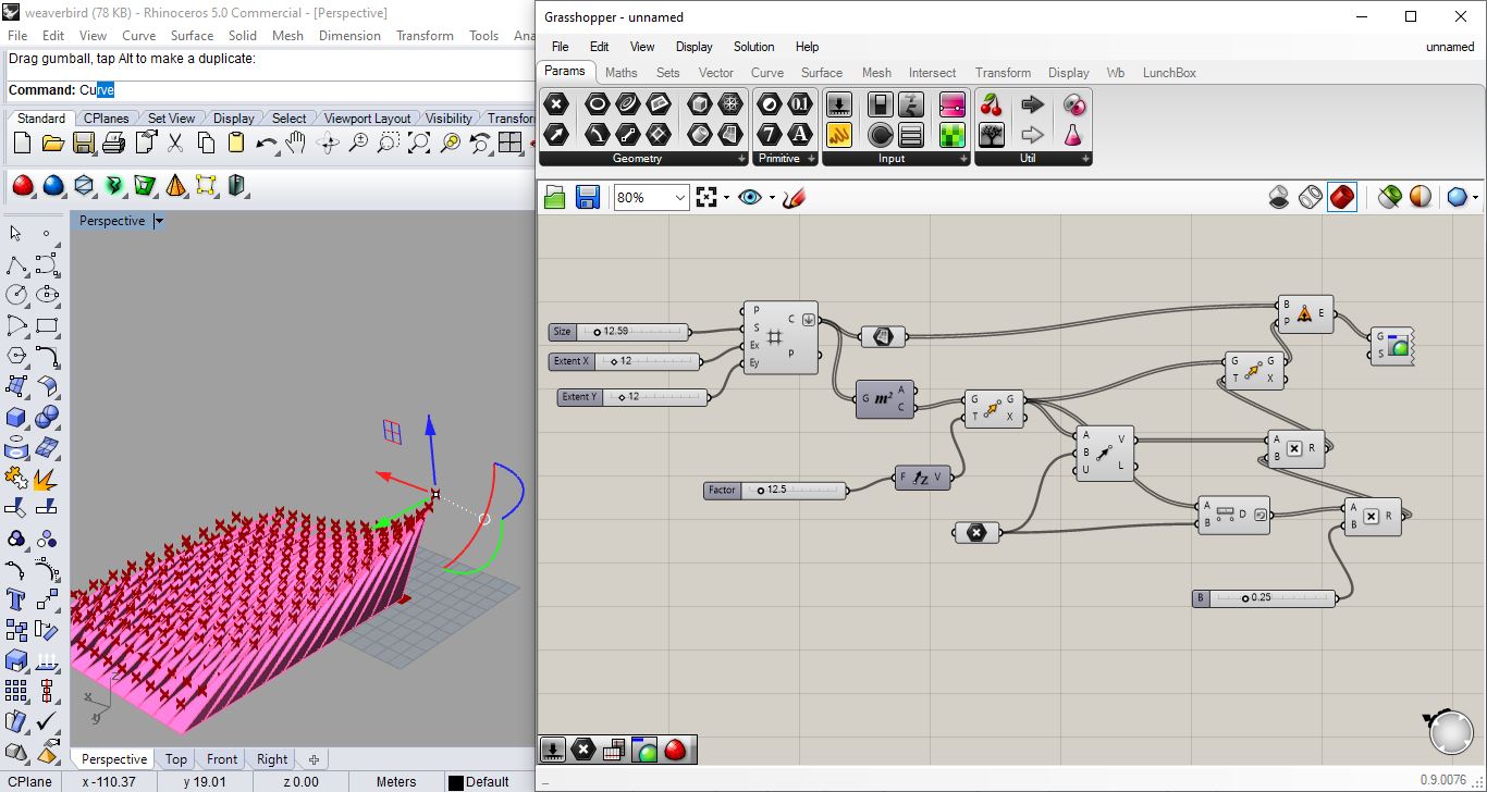
B: define a size using a number slider and connecting it to the size
C: add another 2 number sliders and connect them to “extent Y” and “extent X”
D: flatten cells (with right click on cells)
 E: define a point attractor … type in grasshopper “point”
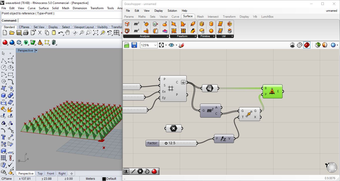
F: surface - free from - extrude point
G: connect cells to base (in extrude point)
H: surface - area tool (to extract the centroid) then write “move” (to move points up) and write “unit Z” and give it a number slider”
I: vector- vector 2pt (take geometry from “move” and plug it in “vector 2pt” as point A ) not write/connect point on grasshopper and connect it in “vector 2pt” as point B
J : right click on unitize on “vector 2pt” - right click set Boolen - True (it means that the vector is one length- so just giving me a direction to the point attractor )
Step 4 : Open Arduino app
Step 5 : Go to file - Sketchbook - choose (firefly firmata).
Step 6 : Then press on Upload button the get the code ready for the next step.
Step 7 : change the last part of the code as following ” only if the Arduino version is the latest version “
Code Used
I used this code to link Arduino (and reading the stretch sensor) to Spikes Rhino Grasshopper Pattern I have created during week03
/*
 Created by Andrew Payne and Jason Kelly Johnson
 Latest Update March 25th, 2015
 Copyright 2015 | All Rights Reserved

 This Firmata allows you to control an Arduino board from Rhino/Grasshopper/Firefly.
 Updates, Questions, Suggestions visit: http://www.fireflyexperiments.com

 1. Plug Arduino boards into your USB port; confirm that your Arduino's green power LED in on
 2. Select your specific Arduino Board and Serial Port (Tools > Board; Tools > Serial Port) *Take note of your Serial Port COM #
 3. Verify (play button) and Upload (upload button) this program to your Arduino, close the Arduino program
 4. then open ... Rhino/Grasshopper/Firefly

 Note: The Firefly Firmata sets the following pins to perform these functions:

 *****ON STANDARD BOARDS (ie. Uno, Diecimila, Duemilanove, Lillypad, Mini, etc.)*****
 ANALOG IN pins 0-5 are set to return values (from 0 to 1023) for analog sensors
 DIGITAL IN pins 2,4,7 will return 0's or 1's; for 3 potential digital sensors (buttons, switches, on/off, true/false, etc.)
 DIGITAL/ANALOG OUT pins 3,5,6,11 (marked with a ~) can be used to digitalWrite, analogWrite, or Servo.write depending on the input status of that Firefly pin
 DIGITAL OUT pins 8,9,10,12,13 can be used to digitalWrite, Servo.write, or analogWrite depending on the input status of that Firefly pin

 *****ON MEGA BOARDS (ie. ATMEGA1280, ATMEGA2560)*****
 ANALOG IN pins 0-15 will return values (from 0 to 1023) for 16 analog sensors
 DIGITAL IN pins 22-31 will return 0's or 1's; for digital sensors (buttons, switches, on/off, true/false, etc.)
 DIGITAL/ANALOG OUT pins 2-13 can be used to digitalWrite, analogWrite, or Servo.write depending on the input status of that Firefly pin
 DIGITAL OUT pins 32-53 can be used to digitalWrite, Servo.write, or analogWrite depending on the input status of that Firefly pin

 *****ON LEONARDO BOARDS*****
 ANALOG IN pins 0-5 are set to return values (from 0 to 1023) for analog sensors
 DIGITAL IN pins 2,4,7 will return 0's or 1's; for 3 potential digital sensors (buttons, switches, on/off, true/false, etc.)
 DIGITAL/ANALOG OUT pins 3,5,6,11 (marked with a ~) can be used to digitalWrite, analogWrite, or Servo.write depending on the input status of that Firefly pin
 DIGITAL OUT pins 8,9,10,12,13 can be used to digitalWrite, Servo.write, or analogWrite depending on the input status of that Firefly pin

  *****ON DUE BOARDS (ie. SAM3X8E)*****
 ANALOG IN pins 0-11 will return values (from 0 to 4095) for 12 analog sensors
 DIGITAL IN pins 22-31 will return 0's or 1's; for digital sensors (buttons, switches, on/off, true/false, etc.)
 DIGITAL/ANALOG OUT pins 2-13 can be used to digitalWrite, analogWrite, or Servo.write depending on the input status of that Firefly pin
 DIGITAL OUT pins 32-53 can be used to digitalWrite, Servo.write, or analogWrite depending on the input status of that Firefly pin
 DAC0 and DAC1 can be used to output an analog voltage on those pins (only available on DUE boards)
 */

#include <Servo.h>            // attach Servo library (http://www.arduino.cc/playground/ComponentLib/Servo)
#include <pins_arduino.h>     // attach arduino pins header file to determine which board type is being used

#define BAUDRATE 115200       // Set the Baud Rate to an appropriate speed
#define BUFFSIZE 512          // buffer one command at a time

/*==============================================================================
 * GLOBAL VARIABLES
 *============================================================================*/

char buffer[BUFFSIZE];        // declare buffer
uint8_t bufferidx = 0;        // a type of unsigned integer of length 8 bits
char *parseptr;
char buffidx;

int counter = 0;
int numcycles = 1000;

#if defined(__AVR_ATmega328P__) || defined(__AVR_ATmega168__)                                                // declare variables for STANDARD boards
  Servo Servo13, Servo12, Servo11, Servo10, Servo9, Servo8, Servo6, Servo5, Servo3;
  Servo SERVO_CONFIG[] = {Servo13, Servo12, Servo11, Servo10, Servo9, Servo8, Servo6, Servo5, Servo3};       // declare array of Servo objects
  int WRITE_PIN_CONFIG[] = {13,12,11,10,9,8,6,5,3};
  int READ_APIN_CONFIG[] = {0,1,2,3,4,5};
  int READ_DPIN_CONFIG[] = {2,4,7};
#endif

#if defined(__AVR_ATmega32U4__) || defined(__AVR_ATmega16U4__)                                               // declare variables for LEONARDO board
  Servo Servo13, Servo12, Servo11, Servo10, Servo9, Servo8, Servo6, Servo5, Servo3;
  Servo SERVO_CONFIG[] = {Servo13, Servo12, Servo11, Servo10, Servo9, Servo8, Servo6, Servo5, Servo3};       // declare array of Servo objects
  int WRITE_PIN_CONFIG[] = {13,12,11,10,9,8,6,5,3};
  int READ_APIN_CONFIG[] = {0,1,2,3,4,5};
  int READ_DPIN_CONFIG[] = {2,4,7};
#endif

#if defined(__AVR_ATmega1280__) || defined(__AVR_ATmega2560__)                        // declare variables for MEGA boards
  Servo Servo2, Servo3, Servo4, Servo5, Servo6, Servo7, Servo8, Servo9, Servo10, Servo11, Servo12, Servo13, Servo32, Servo33, Servo34, Servo35, Servo36, Servo37, Servo38, Servo39, Servo40, Servo41, Servo42, Servo43, Servo44, Servo45, Servo46, Servo47, Servo48, Servo49, Servo50, Servo51, Servo52, Servo53;
  Servo SERVO_CONFIG[] = {Servo2, Servo3, Servo4, Servo5, Servo6, Servo7, Servo8, Servo9, Servo10, Servo11, Servo12, Servo13, Servo32, Servo33, Servo34, Servo35, Servo36, Servo37, Servo38, Servo39, Servo40, Servo41, Servo42, Servo43, Servo44, Servo45, Servo46, Servo47, Servo48, Servo49, Servo50, Servo51, Servo52, Servo53};  // declare array of Servo objects
  int WRITE_PIN_CONFIG[] = {2,3,4,5,6,7,8,9,10,11,12,13,32,33,34,35,36,37,38,39,40,41,42,43,44,45,46,47,48,49,50,51,52,53};
  int READ_APIN_CONFIG[] = {0,1,2,3,4,5,6,7,8,9,10,11,12,13,14,15};
  int READ_DPIN_CONFIG[] = {22,23,24,25,26,27,28,29,30,31};
#endif

#if defined(__SAM3X8E__)                 // declare variables for DUE boards
  Servo FDAC0, FDAC1, Servo2, Servo3, Servo4, Servo5, Servo6, Servo7, Servo8, Servo9, Servo10, Servo11, Servo12, Servo13, Servo32, Servo33, Servo34, Servo35, Servo36, Servo37, Servo38, Servo39, Servo40, Servo41, Servo42, Servo43, Servo44, Servo45, Servo46, Servo47, Servo48, Servo49, Servo50, Servo51, Servo52, Servo53;
  Servo SERVO_CONFIG[] = {FDAC0, FDAC1, Servo2, Servo3, Servo4, Servo5, Servo6, Servo7, Servo8, Servo9, Servo10, Servo11, Servo12, Servo13, Servo32, Servo33, Servo34, Servo35, Servo36, Servo37, Servo38, Servo39, Servo40, Servo41, Servo42, Servo43, Servo44, Servo45, Servo46, Servo47, Servo48, Servo49, Servo50, Servo51, Servo52, Servo53};  // declare array of Servo objects
  int WRITE_PIN_CONFIG[] = {0,1,2,3,4,5,6,7,8,9,10,11,12,13,32,33,34,35,36,37,38,39,40,41,42,43,44,45,46,47,48,49,50,51,52,53}; //Note: first two values correspond to the DAC pins
  int READ_APIN_CONFIG[] = {0,1,2,3,4,5,6,7,8,9,10,11};
  int READ_DPIN_CONFIG[] = {22,23,24,25,26,27,28,29,30,31};
#endif

/*==============================================================================
 * SETUP() This code runs once
 *============================================================================*/
void setup()
{
  Init();                       //set initial pinmodes
  Serial.begin(BAUDRATE);       // Start Serial communication
  #if defined(__SAM3X8E__)      //if the connected board is an Arduino DUE
    analogReadResolution(12);   //Set the analog read resolution to 12 bits (acceptable values between 1-32 bits).  This is only for DUE boards
    analogWriteResolution(12);  // Set the analog write resolution to 12 bits (acceptable values between 1-32 bits).  This is only for DUE boards
  #endif
}

/*==============================================================================
 * LOOP() This code loops
 *============================================================================*/
void loop()
{
  if(Serial){
    ReadSerial();                       // read and parse string from serial port and write to pins
    if (counter >= numcycles){          // Wait every nth loop
      ReadInputs();                     // get input data and print data to the serial port
      counter = 0;                      // reset the counter
    }
    counter ++;                         // increment the writecounter
  }
}

/*==============================================================================
 * FUNCTIONS()
 *============================================================================*/

/*
* Initializes the digital pins which will be used as inputs
*/
void Init(){
  int len = sizeof(READ_DPIN_CONFIG)/sizeof(READ_DPIN_CONFIG[0]); //get the size of the array
  for(int i = 0; i < len; i++){
    pinMode(READ_DPIN_CONFIG[i], INPUT);
  }
}

/*
* Reads the incoming ADC or digital values from the corresponding analog and digital input
* pins and prints the value to the serial port as a formatted commma separated string
*/
void ReadInputs(){
  int len = sizeof(READ_APIN_CONFIG)/sizeof(READ_APIN_CONFIG[0]); //get the size of the array
  for(int i = 0; i < len; i++){
    int val = analogRead(READ_APIN_CONFIG[i]);  //read value from analog pins
    Serial.print(val); Serial.print(",");
  }
  len = sizeof(READ_DPIN_CONFIG)/sizeof(READ_DPIN_CONFIG[0]); //get the size of the array
  for(int i = 0; i < len; i++){
    int val = digitalRead(READ_DPIN_CONFIG[i]); //read value from digital pins
    Serial.print(val); Serial.print(",");
  }
  Serial.println("eol");  //end of line marker
}

/*
* Retrieve the latest incoming serial value and split the string at the comma delimeter.
* When a comma is found, the value is offloaded to a temporary variable and written
* to the corresponding digital pin.
*/
void ReadSerial(){
  char c;    // holds one character from the serial port
  if (Serial.available()) {
    c = Serial.read();         // read one character
    buffer[bufferidx] = c;     // add to buffer
    if (c == '\n') {
      buffer[bufferidx+1] = 0; // terminate it
      parseptr = buffer;       // offload the buffer into temp variable
      int len = sizeof(WRITE_PIN_CONFIG)/sizeof(WRITE_PIN_CONFIG[0]); //get the size of the array
      for(int i = 0; i < len; i++){
        //parse all incoming values and assign them to the appropriate variable
        int val = parsedecimal(parseptr);       // parse the incoming number
        if(i != len - 1) parseptr = strchr(parseptr, ',')+1;   // move past the ","
        WriteToPin(WRITE_PIN_CONFIG[i], val, SERVO_CONFIG[i]);         //send value out to pin on arduino board
      }
      bufferidx = 0;                             // reset the buffer for the next read
      return;                                    // return so that we don't trigger the index increment below
    }                                            // didn't get newline, need to read more from the buffer
    bufferidx++;                                 // increment the index for the next character
    if (bufferidx == BUFFSIZE-1) bufferidx = 0;  // if we get to the end of the buffer reset for safety
  }
}

/*
* Send the incoming value to the appropriate pin using pre-defined logic (ie. digital, analog, or servo)
*/
void WriteToPin(int _pin, int _value, Servo _servo){
  if (_value >= 10000 && _value < 20000)            // check if value should be used for Digital Write (HIGH/LOW)
  {
    if (_servo.attached()) _servo.detach();         // detach servo is one is attached to pin
    pinMode(_pin, OUTPUT);
    _value -= 10000;                                // subtract 10,000 from the value sent from Grasshopper
    if (_value == 1) digitalWrite(_pin, HIGH);
    else digitalWrite(_pin, LOW);
  }
  else if (_value >= 20000 && _value < 30000)       // check if value should be used for Analog Write (0-255)
  {
    if (_servo.attached()) _servo.detach();         // detach servo is one is attached to pin
    pinMode(_pin, OUTPUT);
    _value -= 20000;                                // subtract 20,000 from the value sent from Grasshopper
    analogWrite(_pin, _value);
  }
  else if (_value >= 30000 && _value < 40000)       // check if value should be used for Servo Write (0-180)
  {
    _value -= 30000;                                // subtract 30,000 from the value sent from Grasshopper
    if (!_servo.attached())_servo.attach(_pin);     // attaches a Servo to the PWM pin (180 degree standard servos)
    _servo.write(_value);
  }
  else if (_value >= 40000 && _value < 50000)       // check if value should be used for Analog Write (0-4096) for DACs
  {
    if (_servo.attached()) _servo.detach();         // detach servo is one is attached to pin
    pinMode(_pin, OUTPUT);
    _value -= 40000;                                // subtract 40,000 from the value sent from Grasshopper
    WriteToDAC(_pin, _value);
  }
}

/*
* Parse a string value as a decimal
*/
uint32_t parsedecimal(char *str){
  uint32_t d = 0;
  while (str[0] != 0) {
    if ((str[0] > '50') || (str[0] < '0'))
      return d;
    d *= 10;
    d += str[0] - '0';
    str++;
  }
  return d;
}

/*
* Send the incoming value to the appropriate DAC for DUE boards.
* Note: analogWrite resolution (default is 12 bits) is defined in the Setup function.
*/
  void WriteToDAC(int _pin, int _value){
 #if defined(__SAM3X8E__)
    if(_pin == 0) analogWrite(DAC0, _value);
    else if (_pin == 1) analogWrite(DAC1, _value);
    #endif

  }
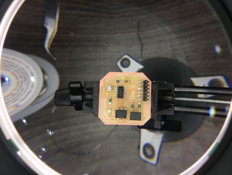
Hero shot !
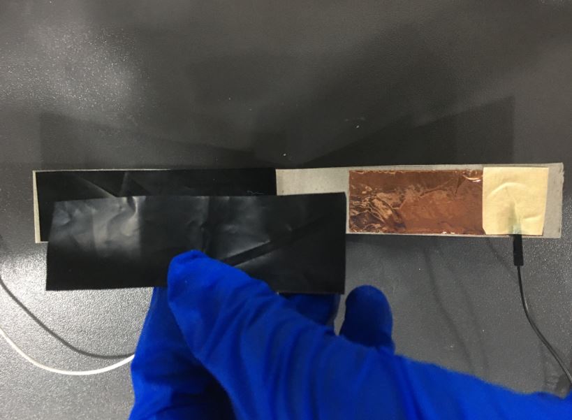
 you can view the change in Panel reading coming out of Arduino pin A0 it was lower before stretching/ or with less stretching to be more accurate “120”
 you can view the change in Panel reading coming out of Arduino pin A0 where became higher after stretching “190” … so the more you stretch the higher the value …
Video
Firstly, Here i made sure it is actually taking/ receiving readings from Arduino
Secondly, Used Data to move/grow in Z-axis and recording how readings on panel change while stretching the fabric
Thirdly, playing with the data input from Arduino to replace any slider determining the growth on Y axis or X -axis so not only Z-axis
Boards
BOR stretch sensor board design.
BOR Schematic design
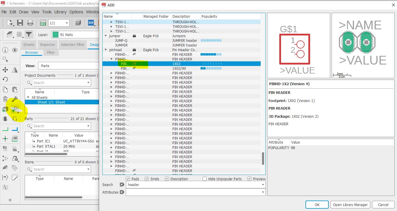 so remember the board i design Week07.I open it’s schematic design on eagle and replaced the Button with a pinhead 1*02 (from add part)so i can connect the stretch sensor to it.
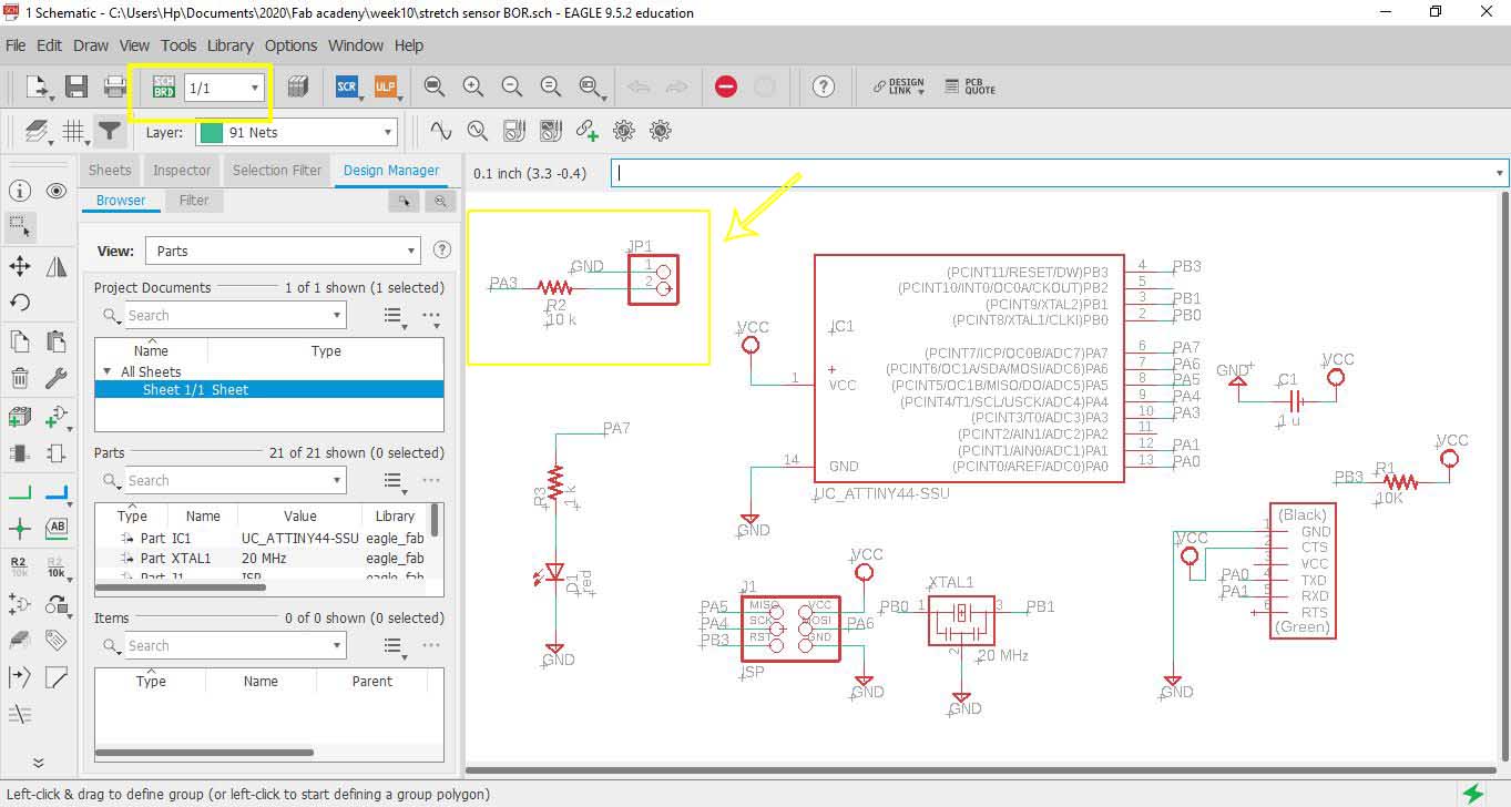 then connected the Pin head 1- to GND and 2- to resistor and one of pins of ATTiny in this PA3
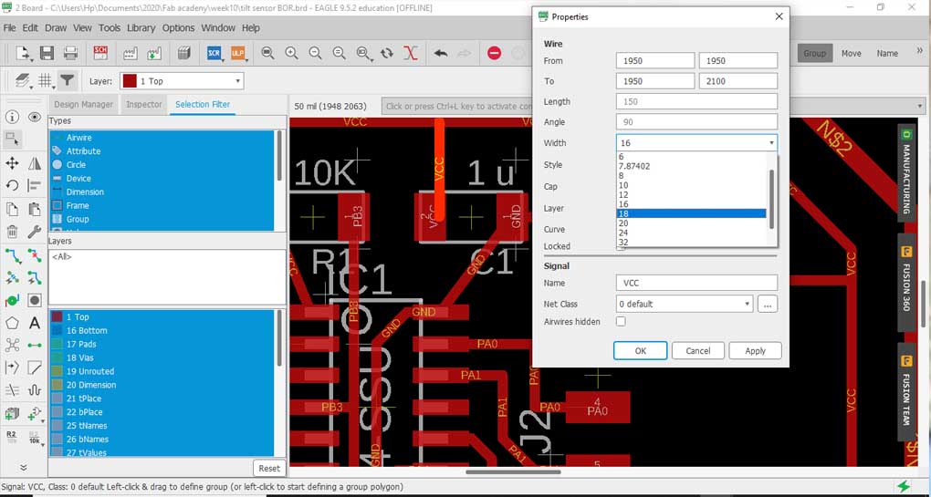 i thought of changing the wire width since during Week07 I got a short circuit and I had to scratch a part that mods didn’t read and the machine didn’t cut by hand a cutter so changed wire width from 16 to 18 BUTTTTTTT
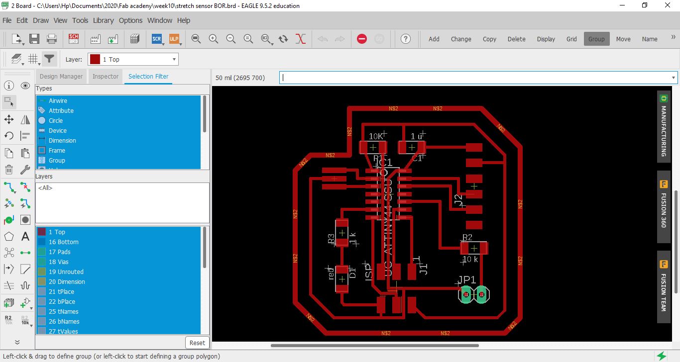 first I got more errors regarding the spacing! but the main problem is I misunderstood this … increasing wire width would create more problems! instead I should be changing the spaces between wires AKA the “clearance”
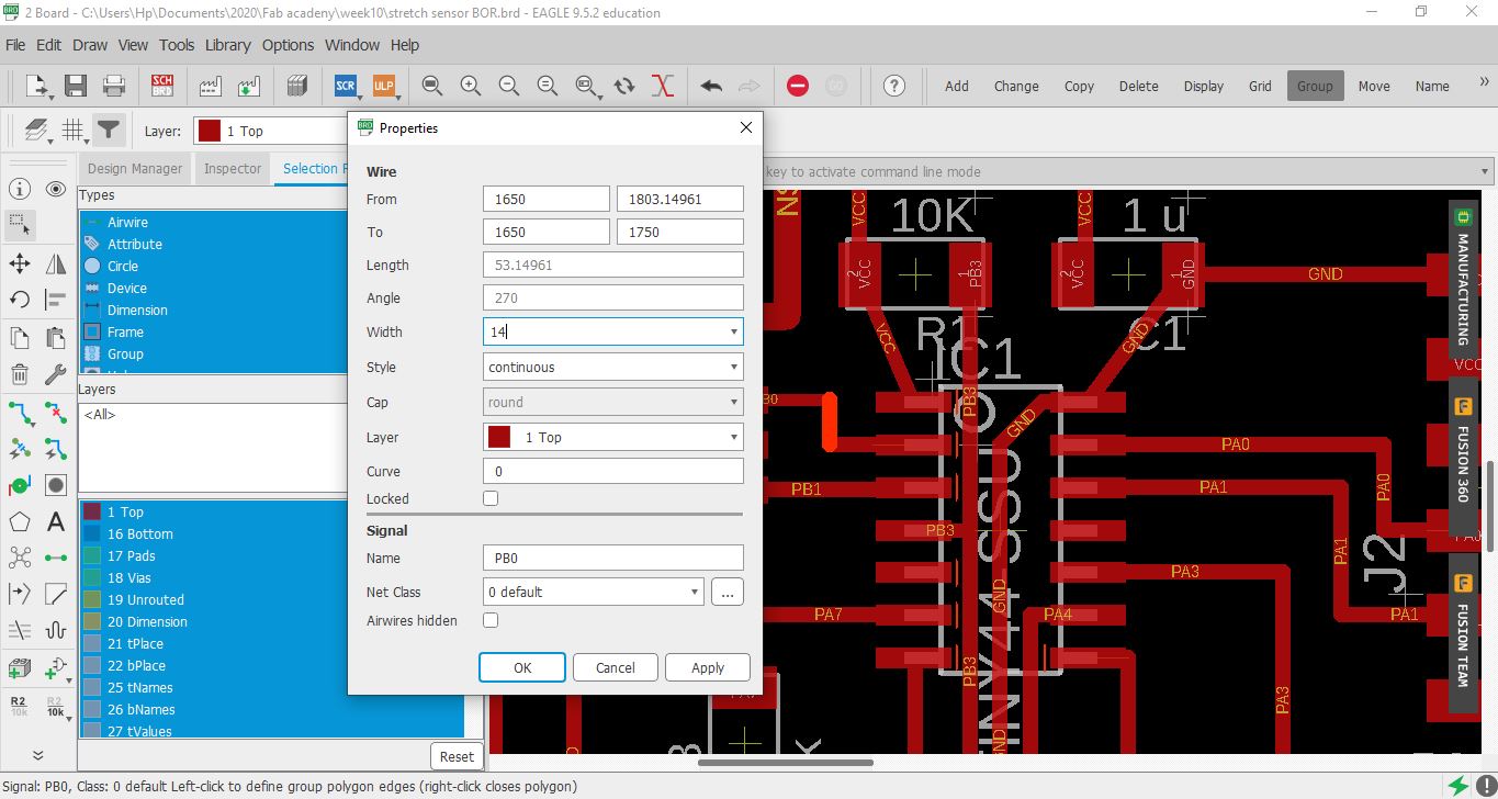 so like a really good girl went back to and changed all wires to from 18 to 14 (even less wire width as it shall be better)
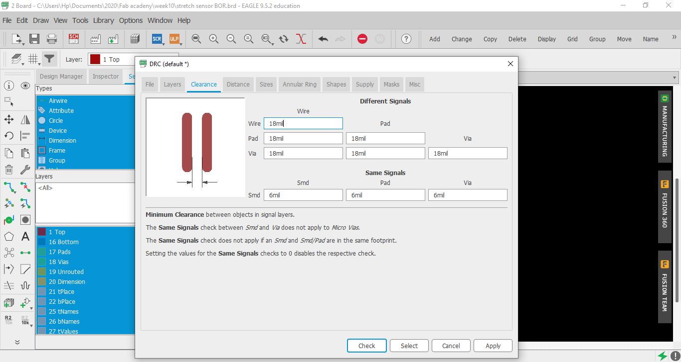 changed the clearance from DRC (bottom left) all to 18mil.
but guess what?
yup got more and more errors yay
changed the clearance from DRC (bottom left) all to 18mil.
but guess what?
yup got more and more errors yay
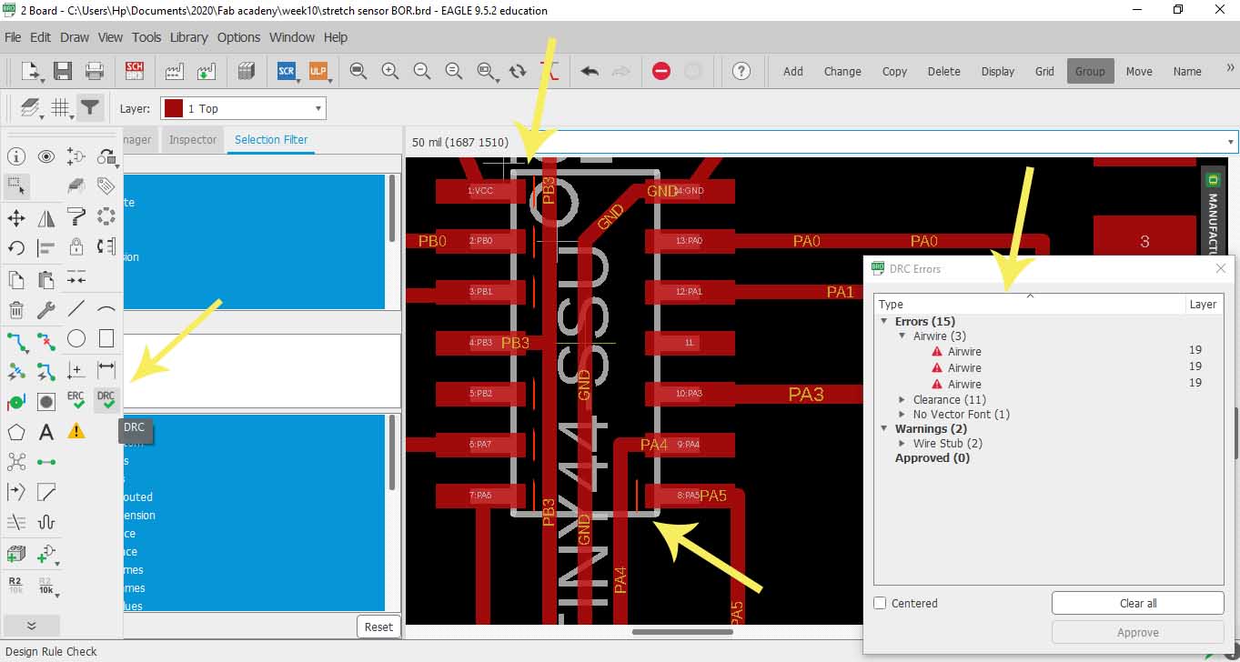 Wonderful! I was scared I’ll have to re-route but nahhh, not today!
Bill Gates was right, once said “I choose a lazy person to do a hard job. Because a lazy person will find an easy way to do it.” Yup ladies and Gentlemen I AM THAT LAZY PERSON so here is what I did…
Wonderful! I was scared I’ll have to re-route but nahhh, not today!
Bill Gates was right, once said “I choose a lazy person to do a hard job. Because a lazy person will find an easy way to do it.” Yup ladies and Gentlemen I AM THAT LAZY PERSON so here is what I did…
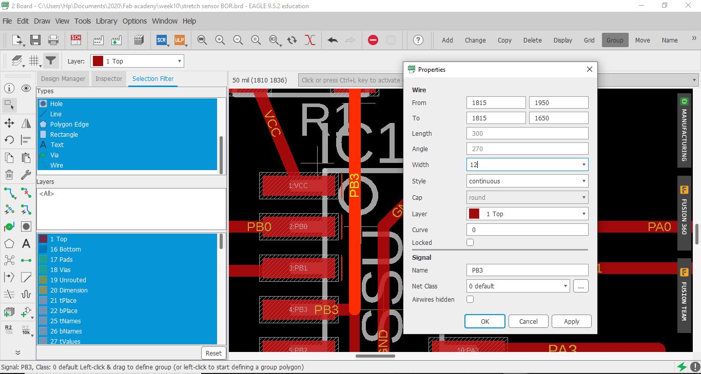 wherever I saw an error, just changed the wire next to them from 14 to 12(wire width by right clicking - properties - width - 12 )
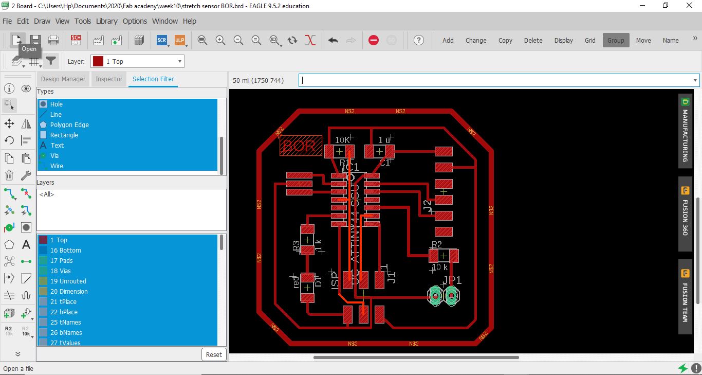 so I ended up only changing the wire width of these highlighted wires and no errors anymore … aka “bbye re-routing”
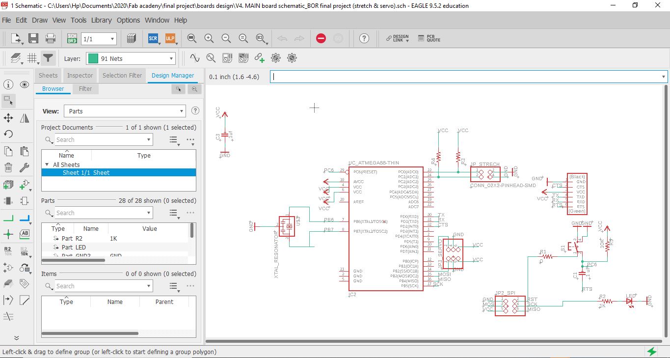
so as you can see here ive used FTDI to read the signal and pin A0 and A1 for the analogue signal
Code Example
I still need to link to Bluetooth
Use the three backticks to separate code.
/*
  ReadAnalogVoltage

  Reads an analog input on pin 0, converts it to voltage, and prints the result to the Serial Monitor.
  Graphical representation is available using Serial Plotter (Tools > Serial Plotter menu).
  Attach the center pin of a potentiometer to pin A0, and the outside pins to +5V and ground.

  This example code is in the public domain.

  http://www.arduino.cc/en/Tutorial/ReadAnalogVoltage
*/

// the setup routine runs once when you press reset:
void setup() {
  // initialize serial communication at 9600 bits per second:
  Serial.begin(9600);
}

// the loop routine runs over and over again forever:
void loop() {
  // read the input on analog pin 0:
  int sensorValue = analogRead(A0);
  delay(500);
  // Convert the analog reading (which goes from 0 - 1023) to a voltage (0 - 5V):
  float voltage = sensorValue * (5.0 / 1023.0);
  // print out the value you read:
  Serial.println(voltage);
}
Soldering
Final Project Main board
Controlling servo motor with a DIY flex sensor from Batoul Al-Rashdan on Vimeo.
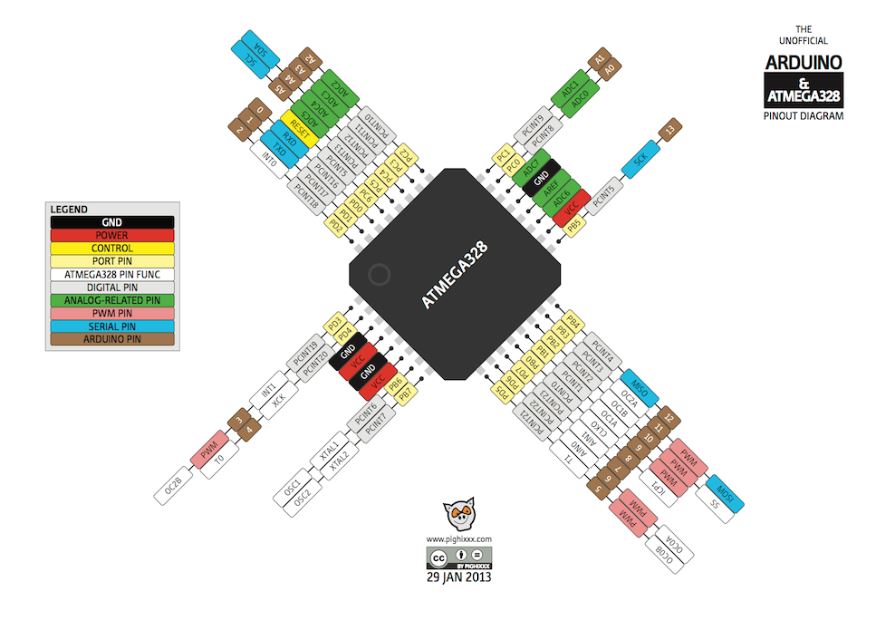 so here I paid attention to using the right pins that serve the Servo Motor Pin number 6 for example because its PWM which is Pulse Width Modulation, is a technique for getting analog results with digital means that i need for the servo motor.
 here you can see the board design after I successfully routed all the connections
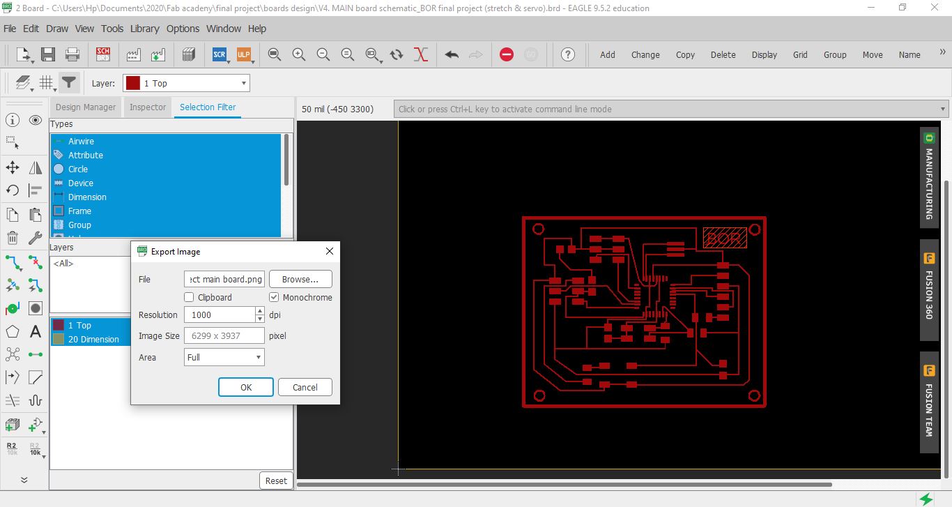
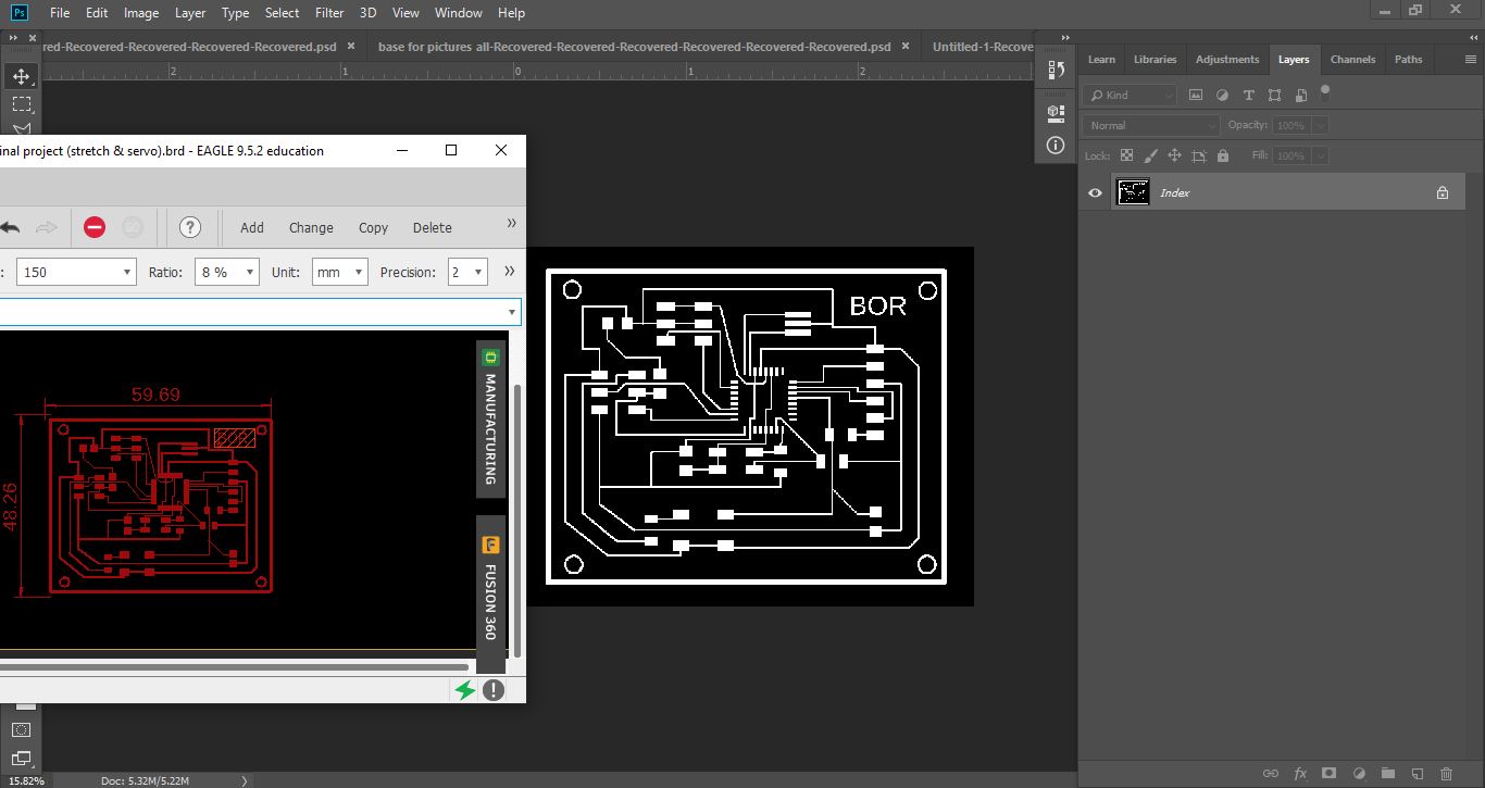 I exported my design and edited it using Photoshop in order to get the traces and the interior “outline” PNG
 a previous designed i designed for the servo and trestch sensor but didnt work it somehow and i tried to figure out why but ended up making another one from scratch which is the final result below
Finally i have the new design all ready so here is the traces and the interior “outline”
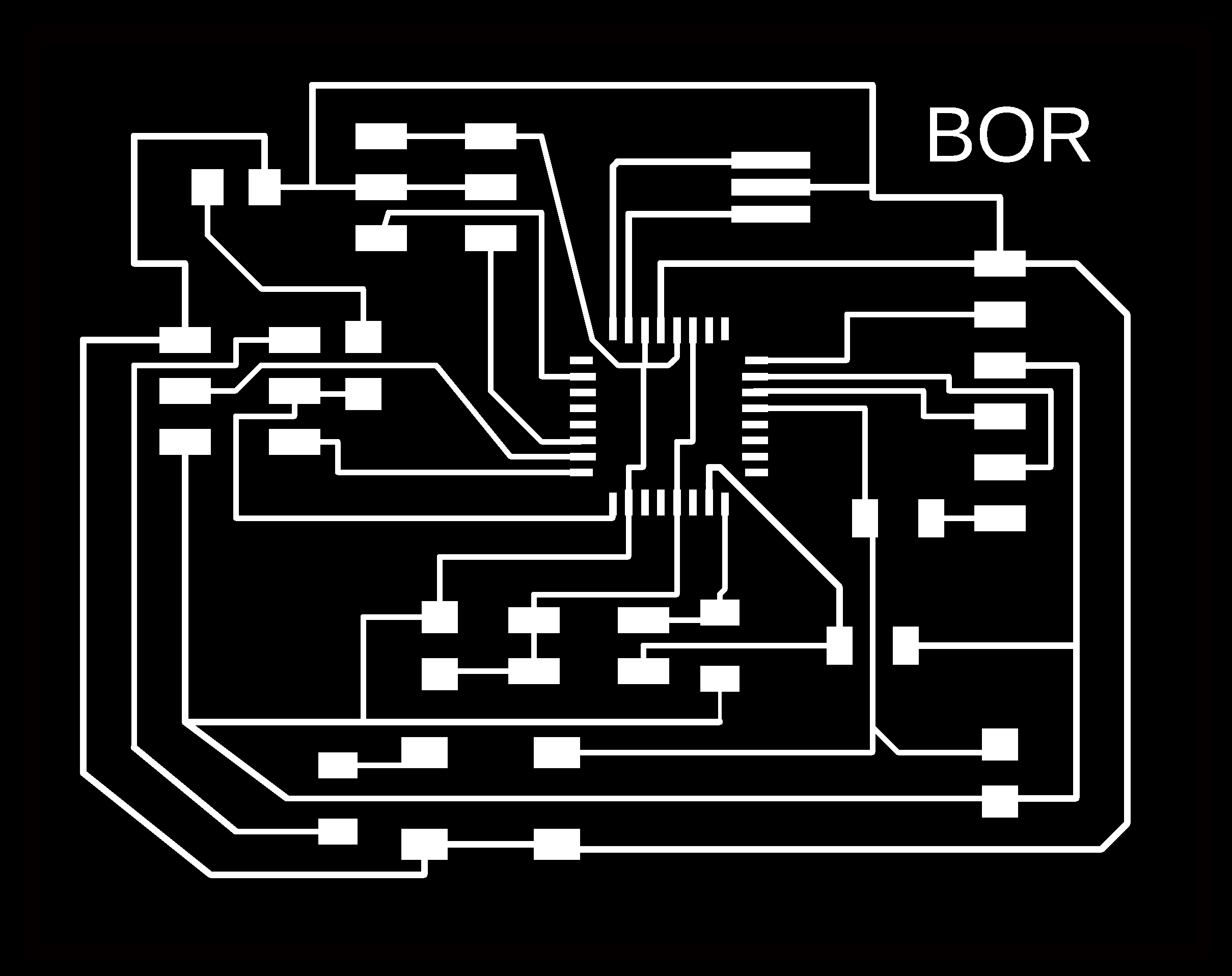

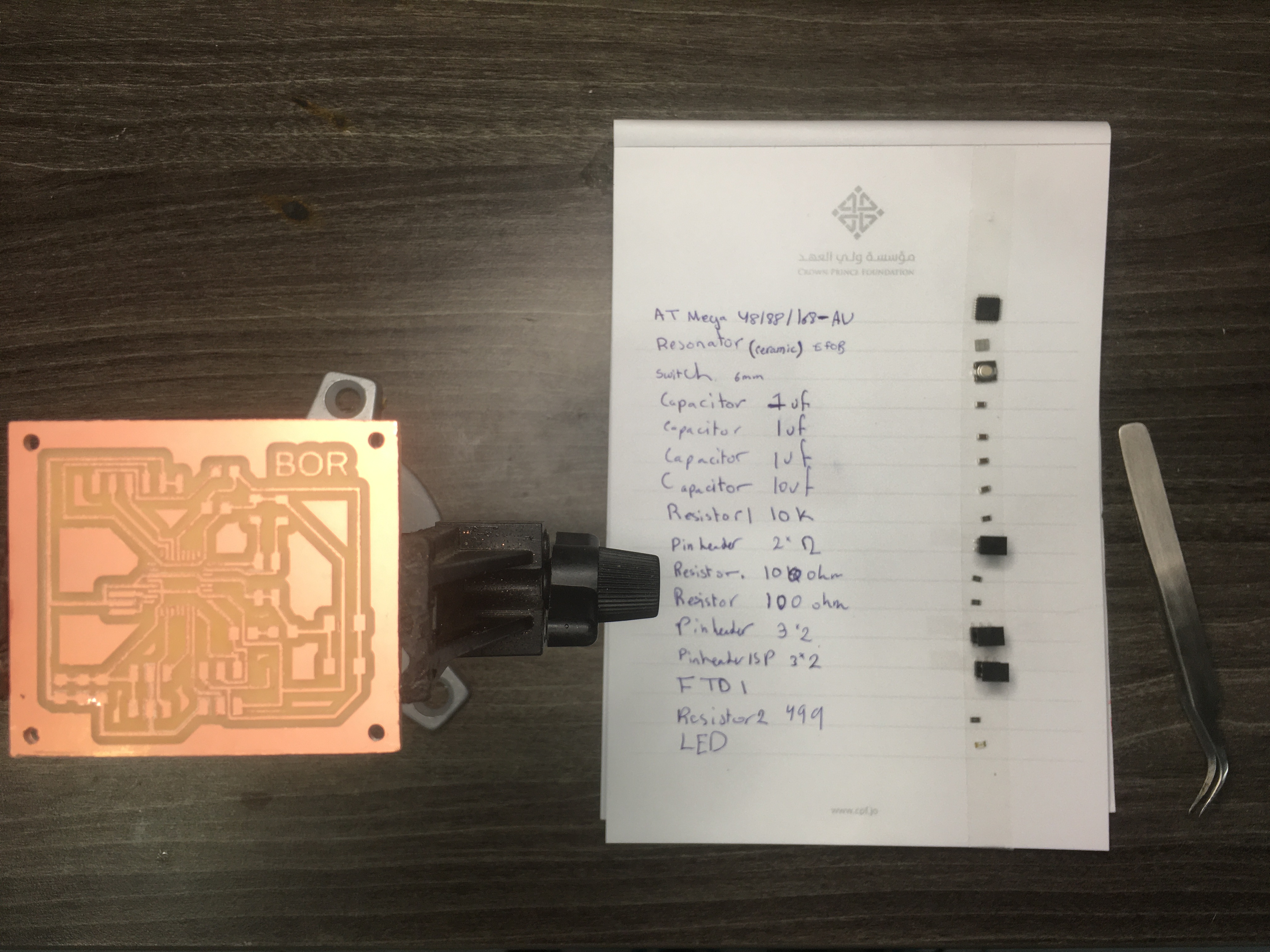
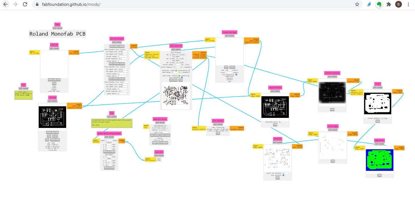
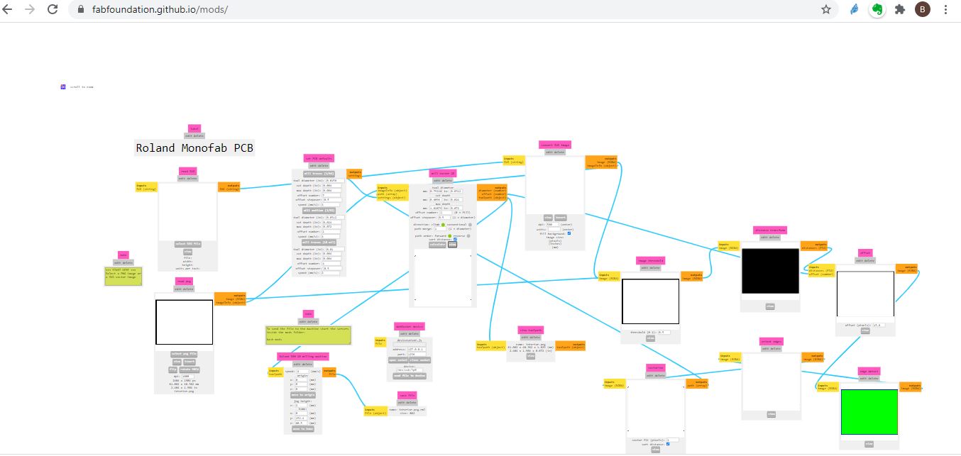
That i used later on mods to cut my via Rolan Monofab PCB machine
i used arduino to program my board after i downladed the need libraries for windows check week 9 for specific details
Code
Servo- Flex code … for my final project
#include <Servo.h>

Servo myServo;
int flexValue;
int servoPosition;
const int flexPin = A0;

void setup()
{
  myServo.attach(6);
  Serial.begin(9600);
}

void loop()
{


  flexValue = analogRead(flexPin);

  servoPosition = map(flexValue, 450 , 1023 , 0, 125);
  servoPosition = constrain(servoPosition, 0, 125);
  Serial.println(flexValue);
 // Serial.println(servoPosition);
  myServo.write(servoPosition);

  delay(100);
}
Hero shot
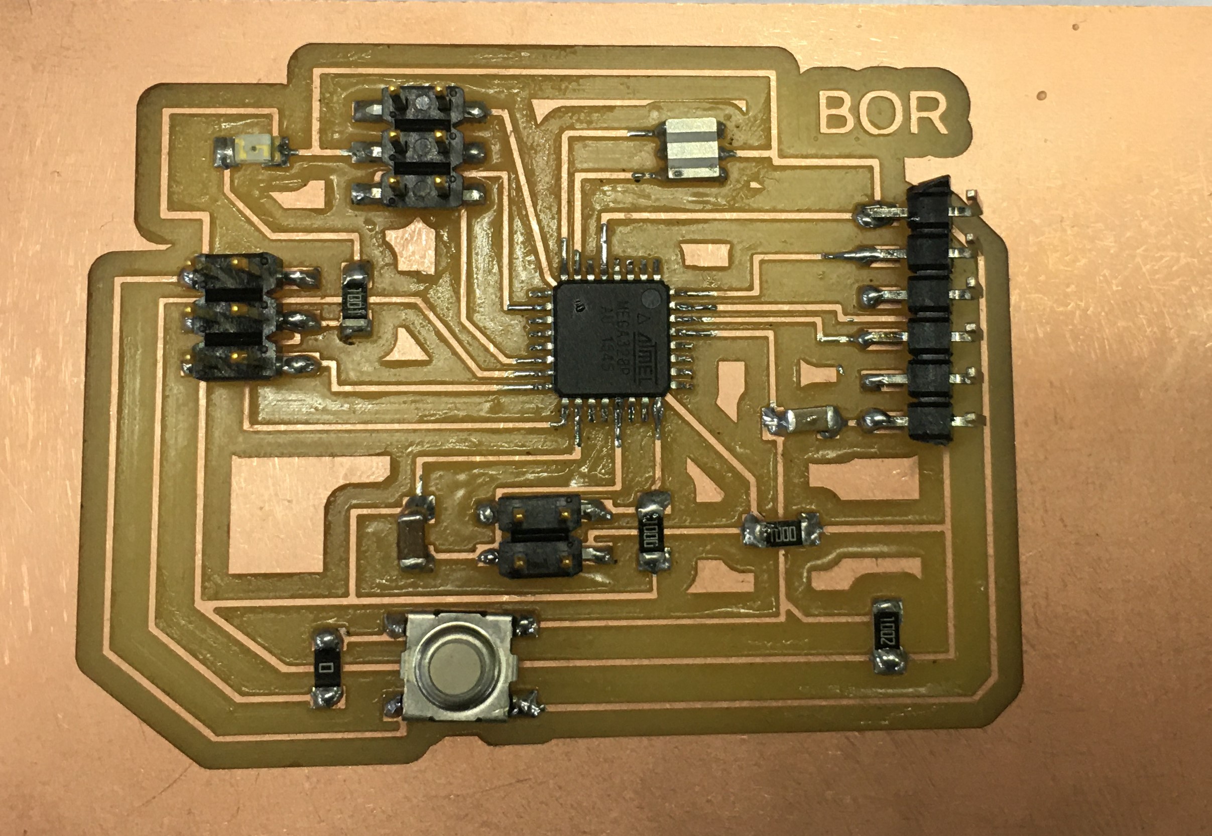
Proof it works with a video
Board working check from Batoul Al-Rashdan on Vimeo.
Mold for the Glove
this wasn’t a very practical method of doing a glove (during Mold and cast week) but felt like documenting my trial of making a mold to fabricate a silicone glove and embedding the sensor inside the silicone…
Tried to use Week 16 to create stretch sensor with a silicone glove and then I changed my mind wanted to try it for output silicon on fabric so the servo moves underneath
I used SORTA-Clear™ 18
Food safety technical datasheet
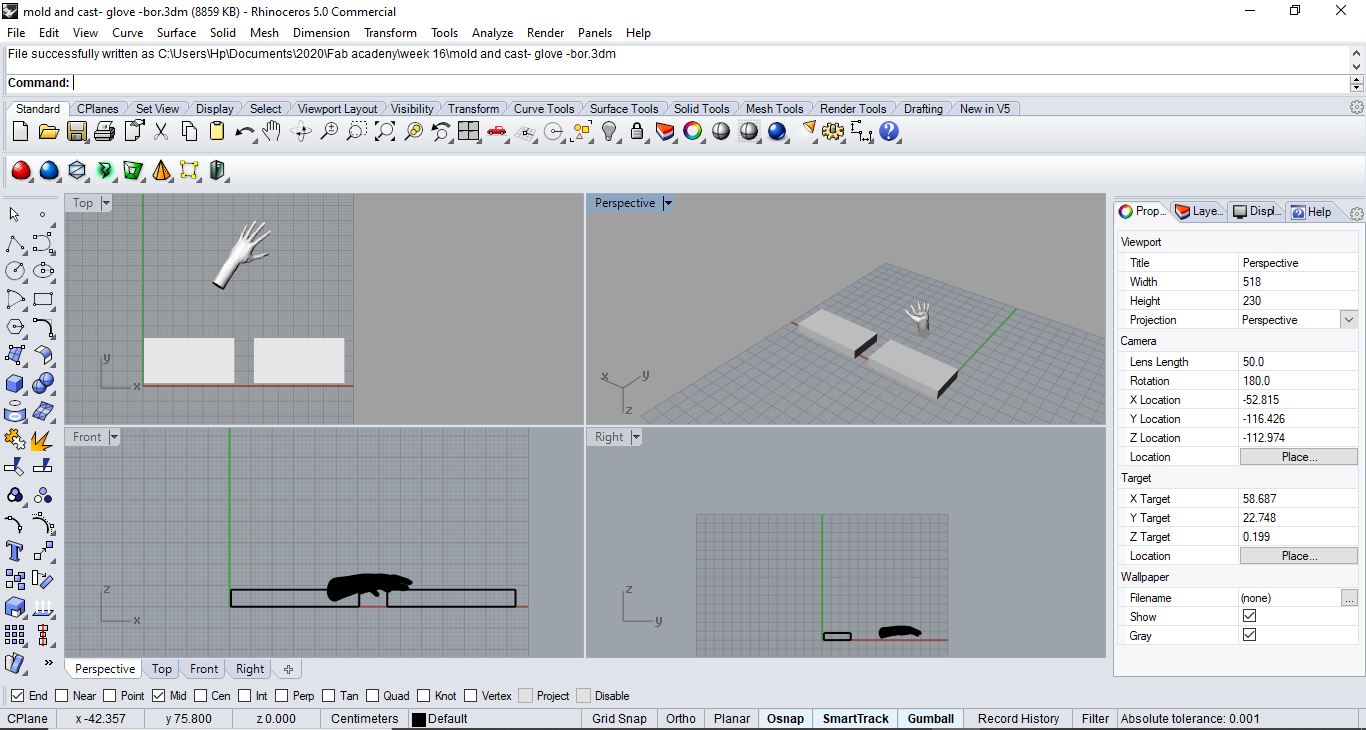
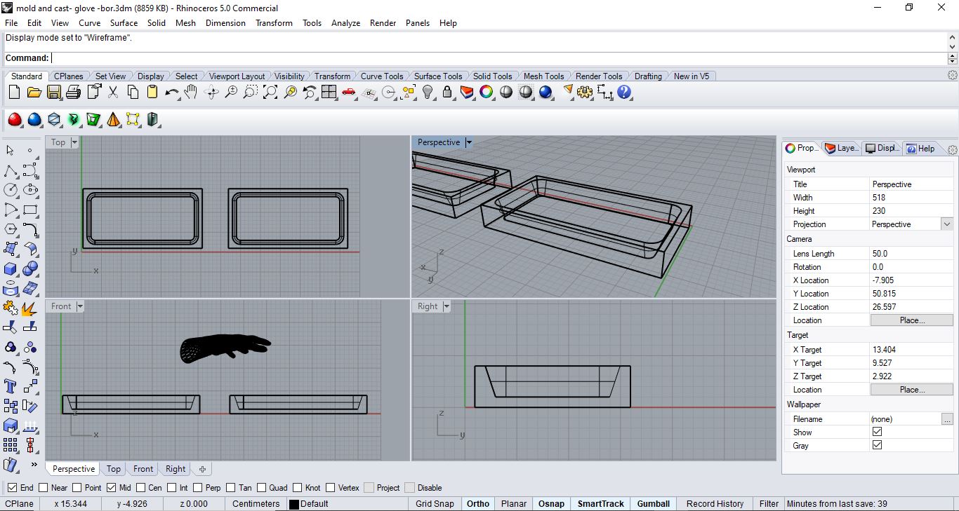
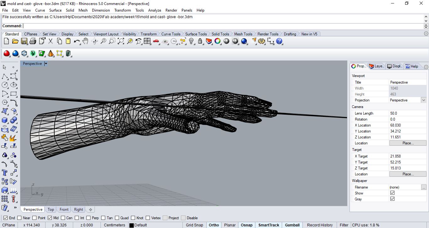
Step 1: so firstly I prepared the file by cutting my hand and made 2 boxes with the dimensions of the available wax at the lab ( each wax is 15304 cm) so each box size is ( each wax is 15304 cm) with solid creation tool on the right (box)
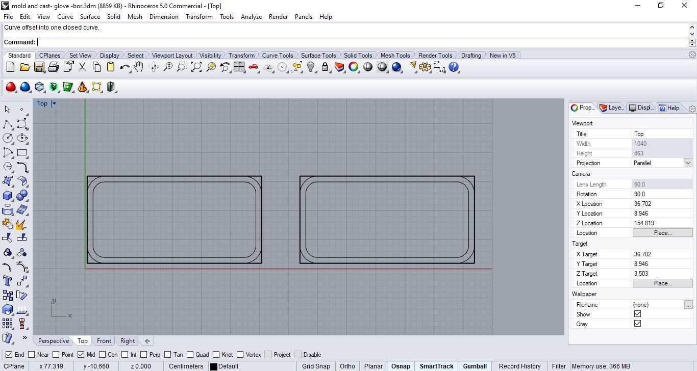
 Step2: from now on I’ll use the top view, then draw a rectangle (rounded corners) on the boarders of each rectangle, select curve and offset 1 cm which would be the mold wall
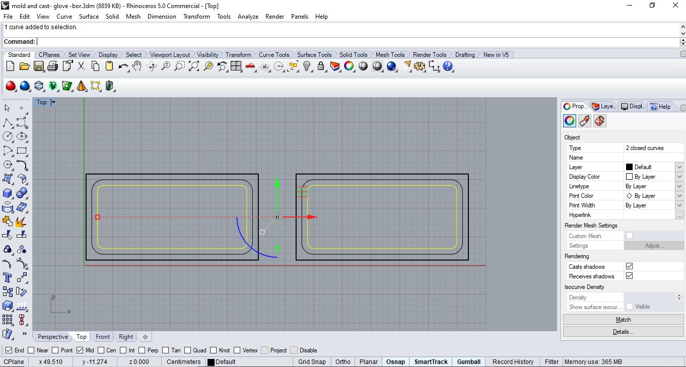
 Step3: then delete the outer rounded corner rectangle and do another offset from the interior one and after selecting them I go the front view
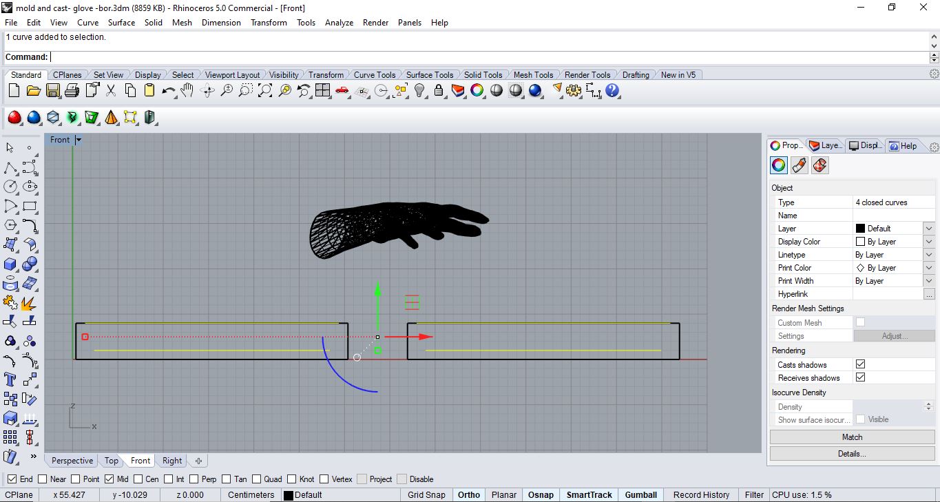
 Step4: so I moved the highlighted curves in step3 negative 3cm so I would have the bottom of the container like mold
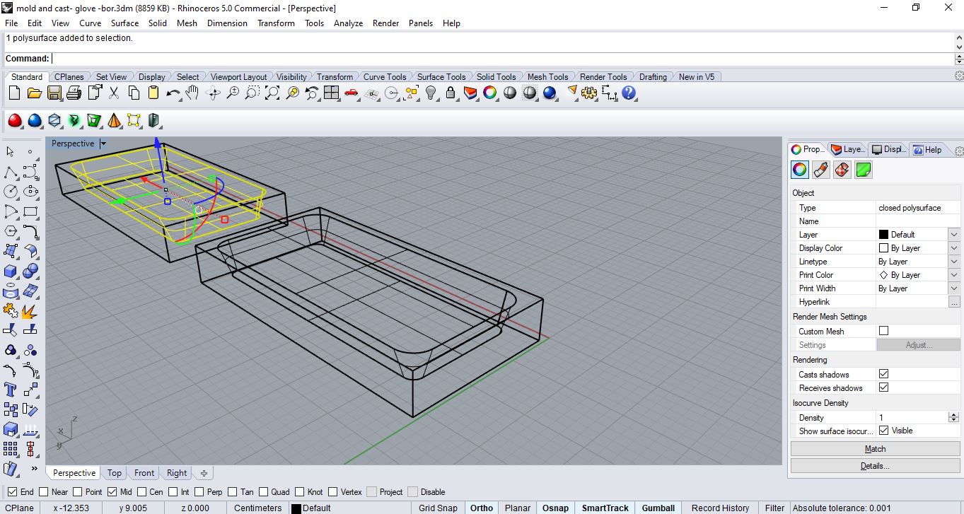
 Step5: then i would also select the other outer curves and command “loft” to connect between them then select them and use command “cap planer holes”
 Step6: select it one and use command “boolen dfference” to subtract them from each other and end up with the basic mold container
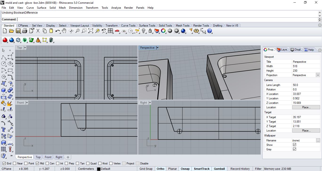
 Step7: select inner curves and offset .5 cm and create spheres at the corners with a .3 cm radius, then copy and paste to each corner
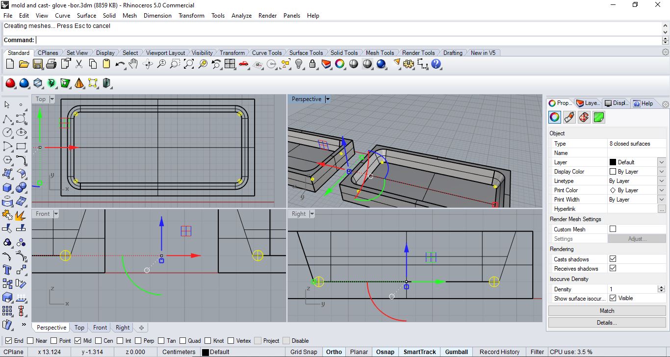 just make one positive and one negative using command “boolen difference” so they would close as a case
 so after lots of trials and lots of scans of my hand and stl files even from make human and different orientations even after modifications
 and then i decided to ditch that and instead of trying to do a mold for my input for my final project … try to do for the output!
Stretch/ flexi sensor
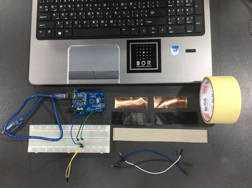
making my own DIY flex sensor from available materials at the lab due to the pandemic
Glove/Sensor
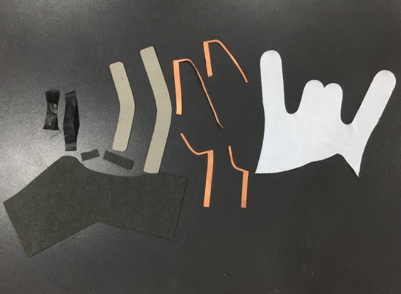
Design
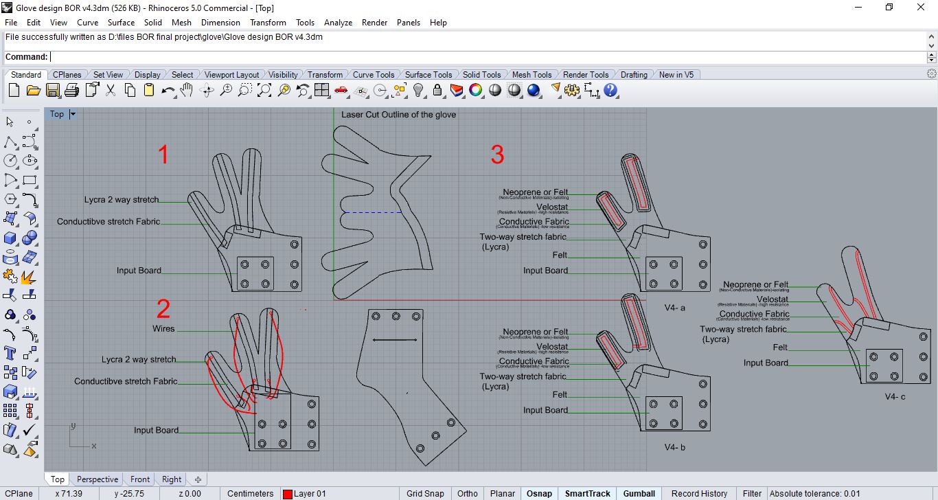
Names of 1. Conductive Fabric 2. Velostat 3. Felt Fabric 4. Lycra Fabric 5. Felt Fabric
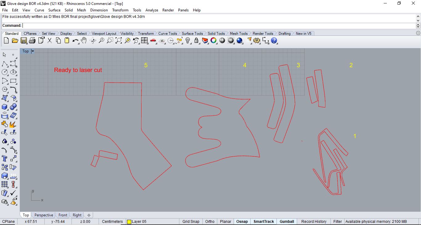
Fabrication
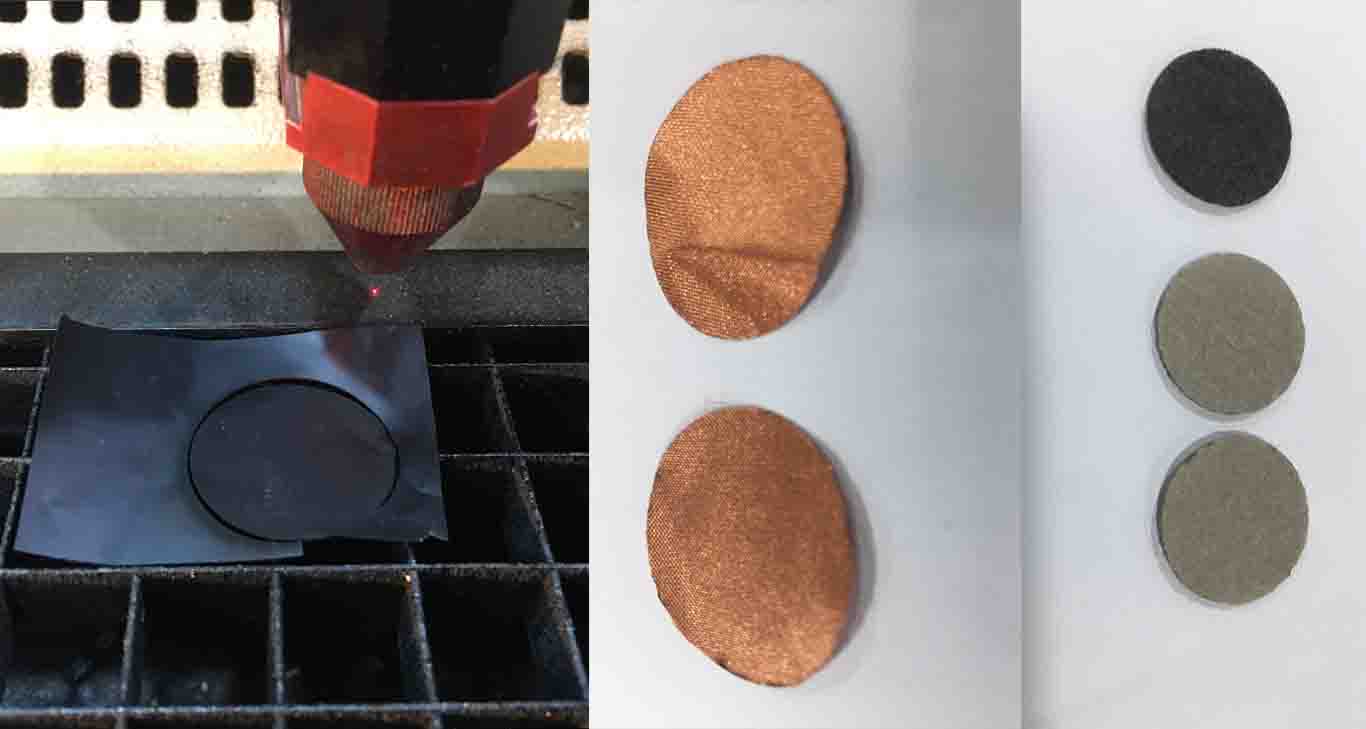 here are sample tests I have done before actually cutting my design just to try the setting and optimize the setting to get prefect results after several iterations
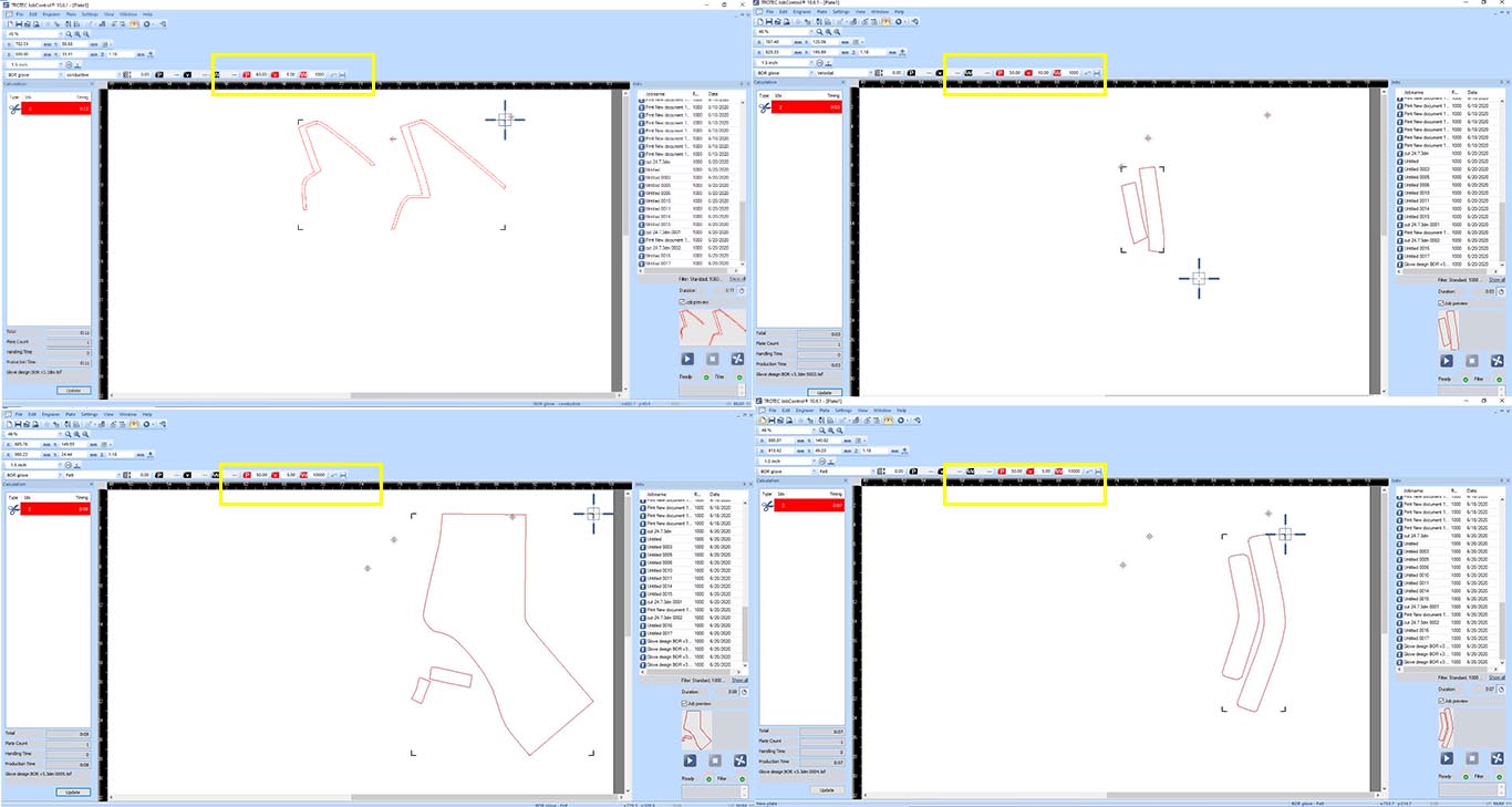 here the setting to laser cut the fabrics needed to make the flexi/stretch sensor … explained more in tables below
Conductive Fabric laser settings
| Output | Power | Speed | Frequency | Passes | Color |
|---|---|---|---|---|---|
| Cut | 60 | 5 | 1000 Hz | 1 | Red |
Lycra Fabric laser settings
| Output | Power | Speed | Frequency | Passes | Color |
|---|---|---|---|---|---|
| Cut | 40 | 2 | 1000 Hz | 1 | Red |
Felt Fabric laser settings
| Output | Power | Speed | Frequency | Passes | Color |
|---|---|---|---|---|---|
| Cut | 50 | 5 | 1000 Hz | 1 | Red |
Velostat laser settings
| Output | Power | Speed | Frequency | Passes | Color |
|---|---|---|---|---|---|
| Cut | 50 | 10 | 1000 Hz | 1 | Red |
laser cut glove from Batoul Al-Rashdan on Vimeo.
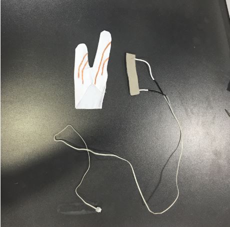
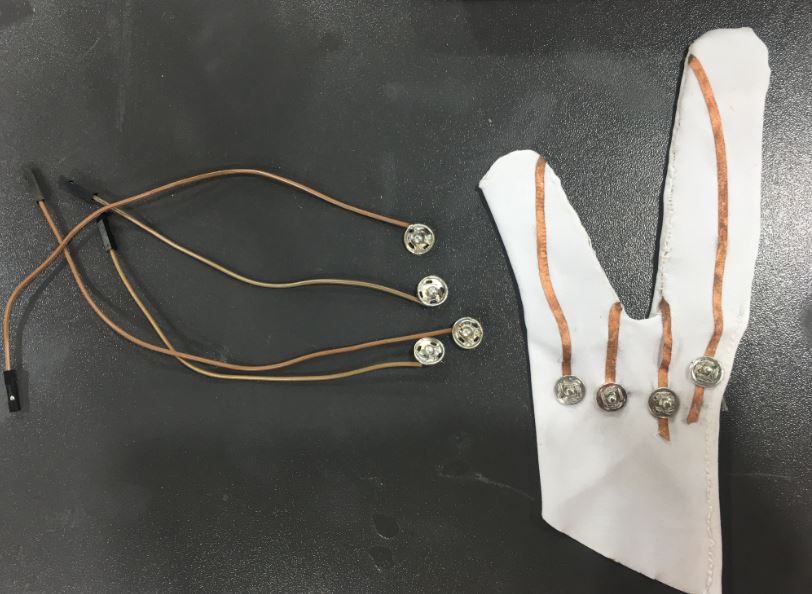 at first i tired so hard making the connections through conductive fabric and then pins and wires but it was unstable due to tension tearing the conductive fabric after several movements cuz has no protective layer on top
as a result i modified the design to be connected internally with real thin wire to maintain a stable connection
remmeber the 3D scan i have done on my hand week06 i used my hand scan to grow voronoi bracelet to extend the glove design and have a 3D printed addition to the packaging of the overall glove by using grasshopper definition
Bracelet
Design
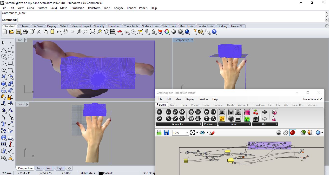
This voronoi bracelet designed to grew on my 3D hand scan as a result fitting my real hand with spaces to put Bluetooth as well as input board for future Plan to connect stretch-flexi sensor with the output(servo moving spikes) via Bluetooth and stop seeing the wire … I wanted to prepare the design for such step from early stages as a designer I enjoy designing
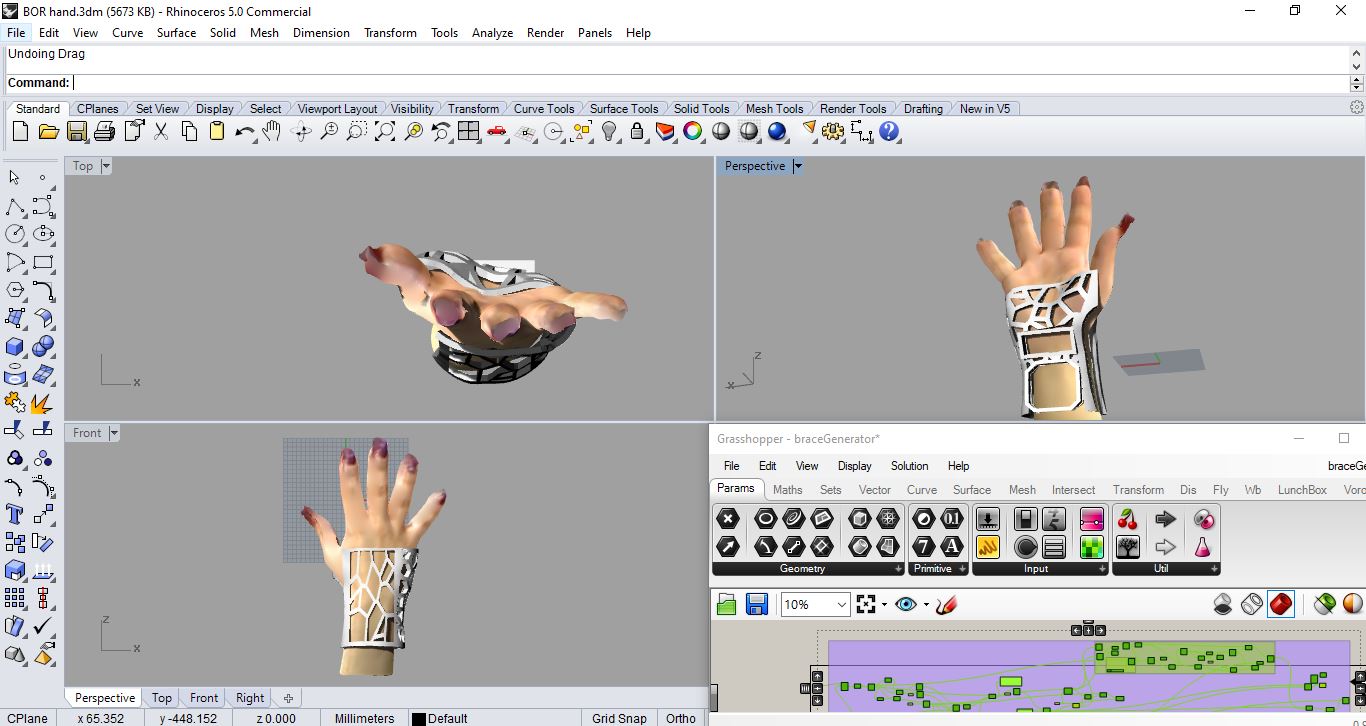 here the finished outcome of the voroni bracelet on my hand where it support and has empty spots fit exactly to my inpout board and Bluetooth for future reference of connecting my final project via bluetooth not wires anymore cool no? and it’s an exact fit to my hand and ready to print