3. Computer Aided design
This week regarding Computer Aided Design & Parametric Design.
Files to download
Research
“Algorithmic design is not simply the use of computer to design architecture and objects. Algorithms allow designers to overcome the limitations of traditional CAD software and 3D modelers, reaching a level of complexity and control which is beyond the human manual ability”.
AAD_Algorithms-Aided Design
* Parametric Strategies Using Grasshopper®
* Grasshopper environment and plug-in software
* Parametric modeling and advanced data management
* NURBS curves and surfaces
* Meshes and Subdivision Surfaces
* Digital fabrication techniques
Recursions
* Form-finding strategies
* Particle-spring systems
* Topology Optimization
* Evolutionary solvers
* Environment-informed design
Useful links and files to download
The key is exposure through out 2D drawing, 3d modeling, generative design & coding
Vector VS. raster graphics
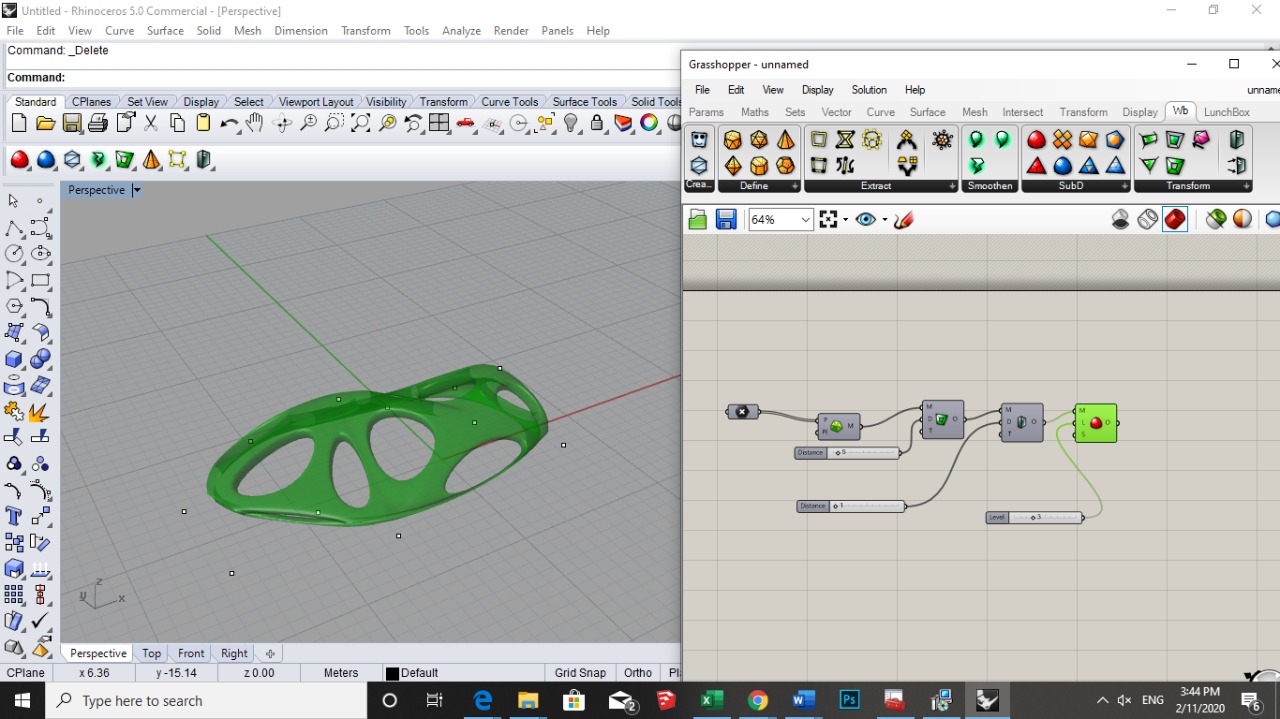
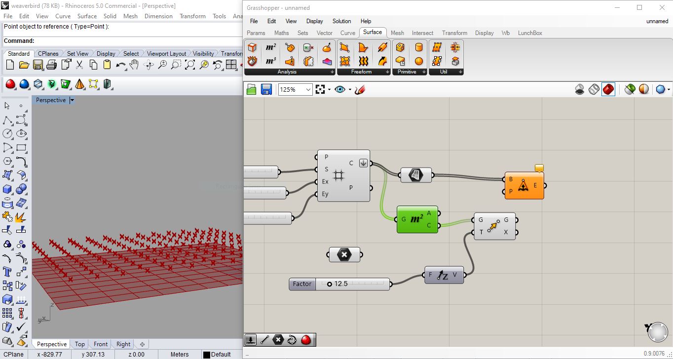
Rhino + Grasshopper
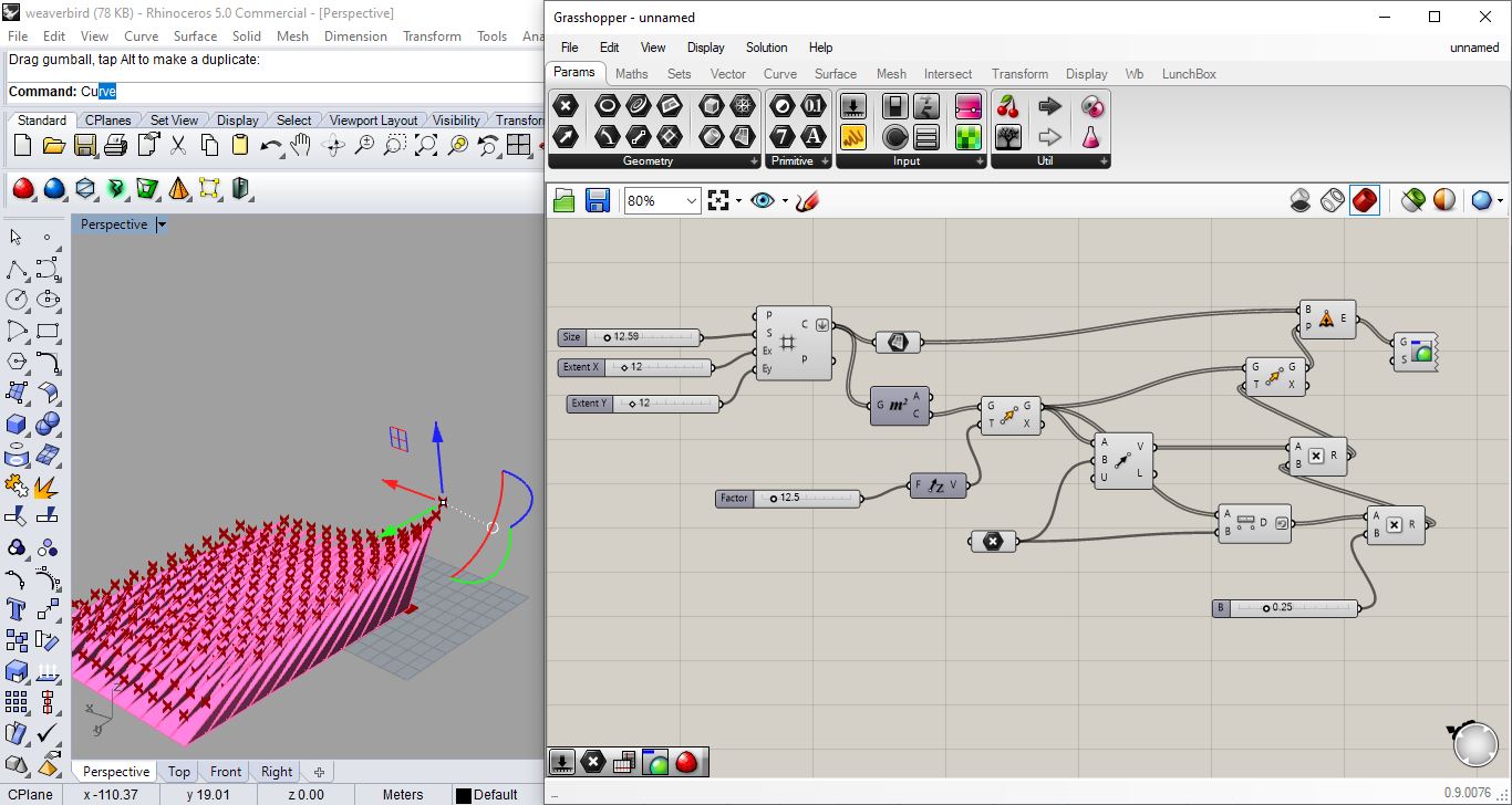
Playing with rhino and grasshopper possibilities


Weaverbird Effect plugin
just a trial
Experimenting with pattern i would use on fabric for final project
 step1: vector - grid -square grid
srep2: define a size using a number slider and connecting it to the size
step3: add another 2 number sliders and connect them to “extent Y” and “extent X”
step4: flatten cells (with right click on cells)
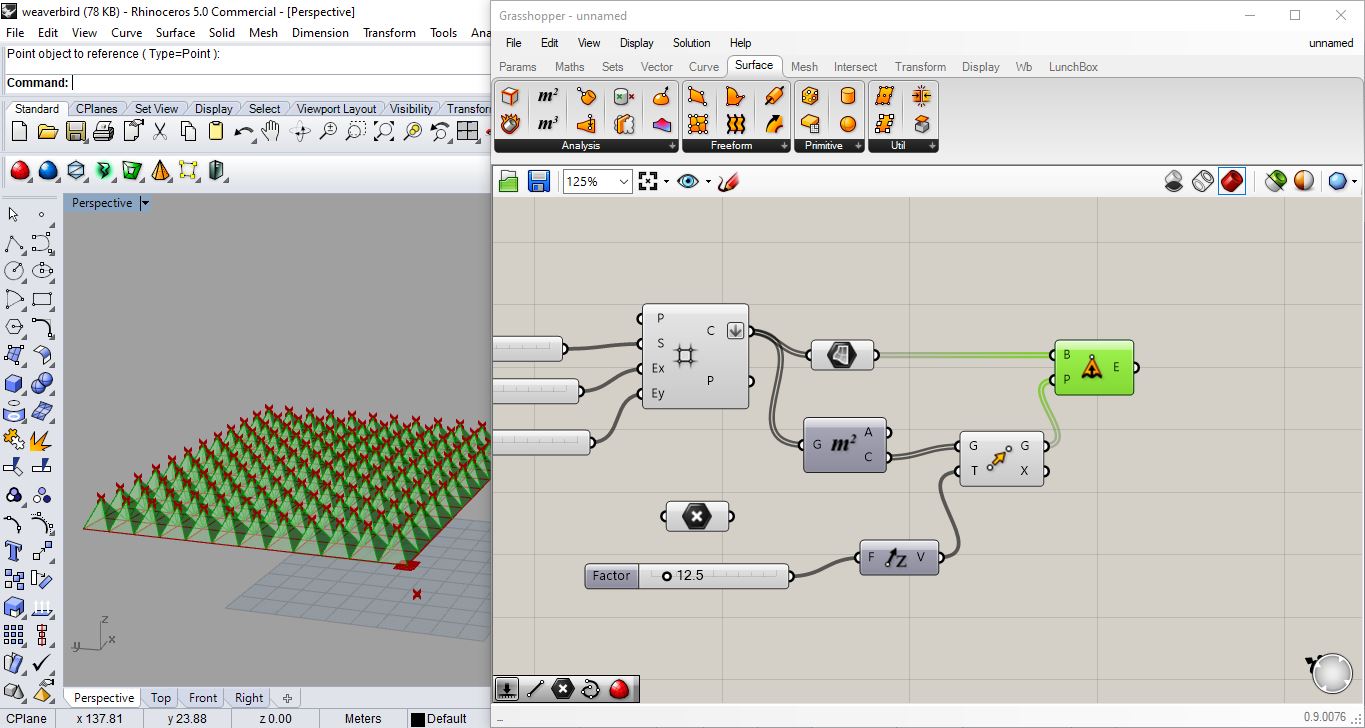 step5: define a point attractor … type in grasshopper “point”
step6: surface - free from - extrude point
step7: connect cells to base (in extrude point)
step8: surface - area tool (to extract the centroid) then write “move” (to move points up) and write “unit Z” and give it a number slider”
step9: vector- vector 2pt (take geometry from “move” and plug it in “vector 2pt” as point A ) not write/connect point on grasshopper and connect it in “vector 2pt” as point B
step10 : right click on unitize on “vector 2pt” - right click set Boolen - True (it means that the vector is one length- so just giving me a direction to the point attractor )
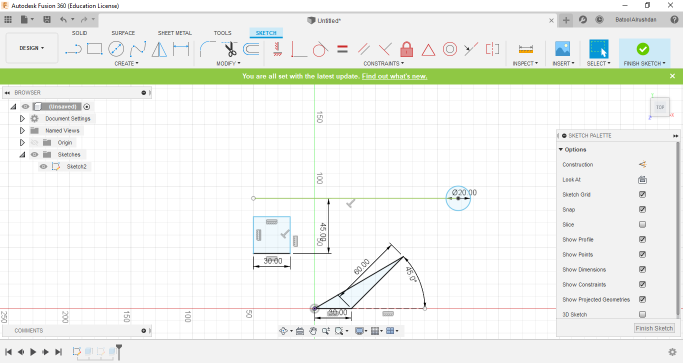
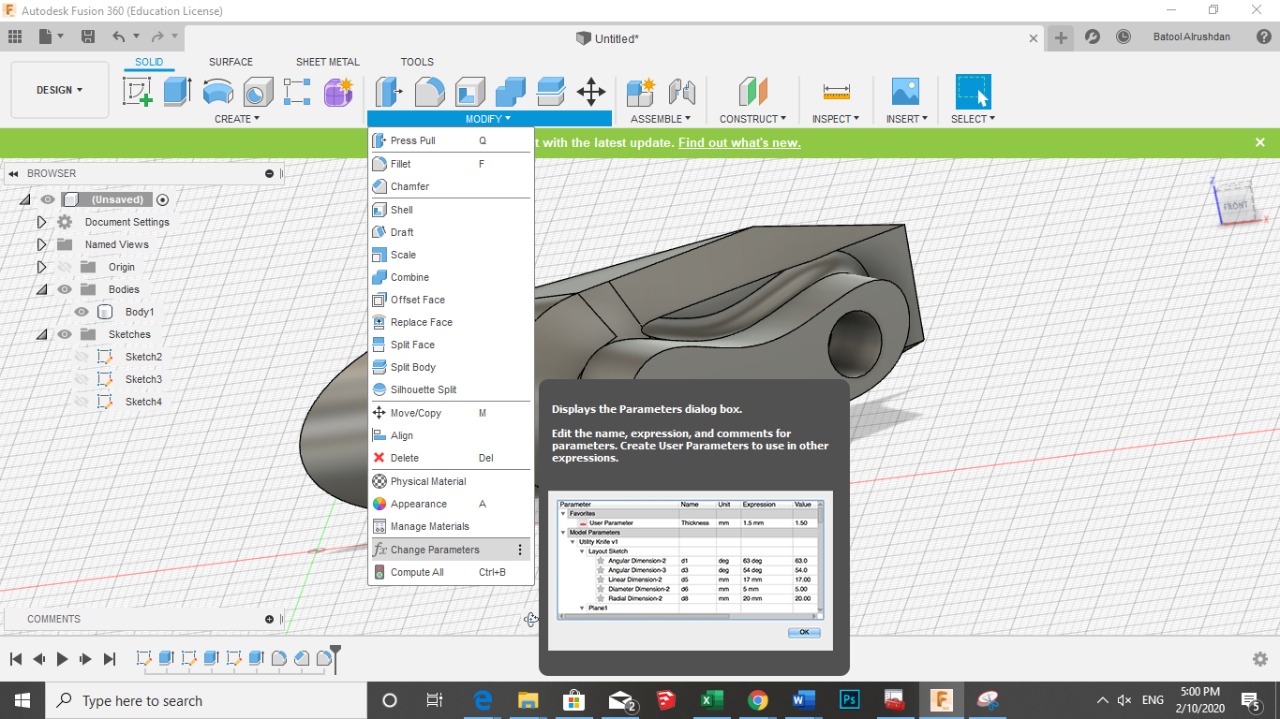
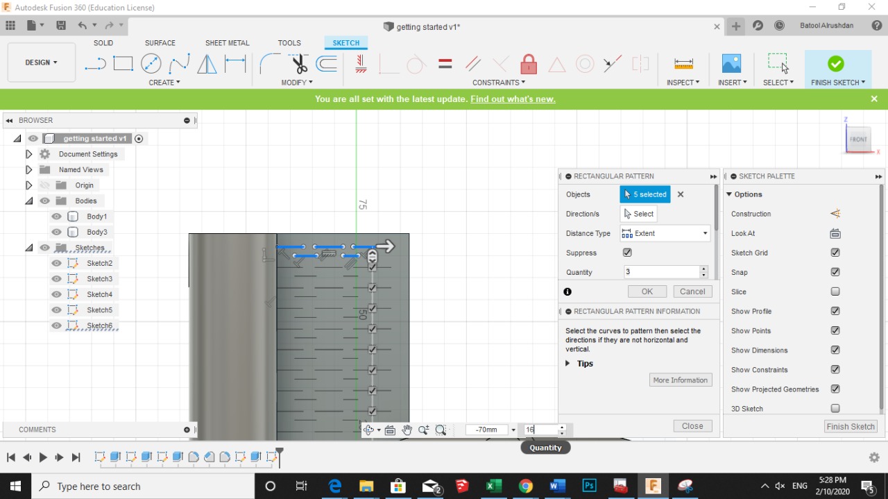
Autodesk Fusion 360
just truials tryina get familair with the Autodesk Fusion 360
AutoCAD
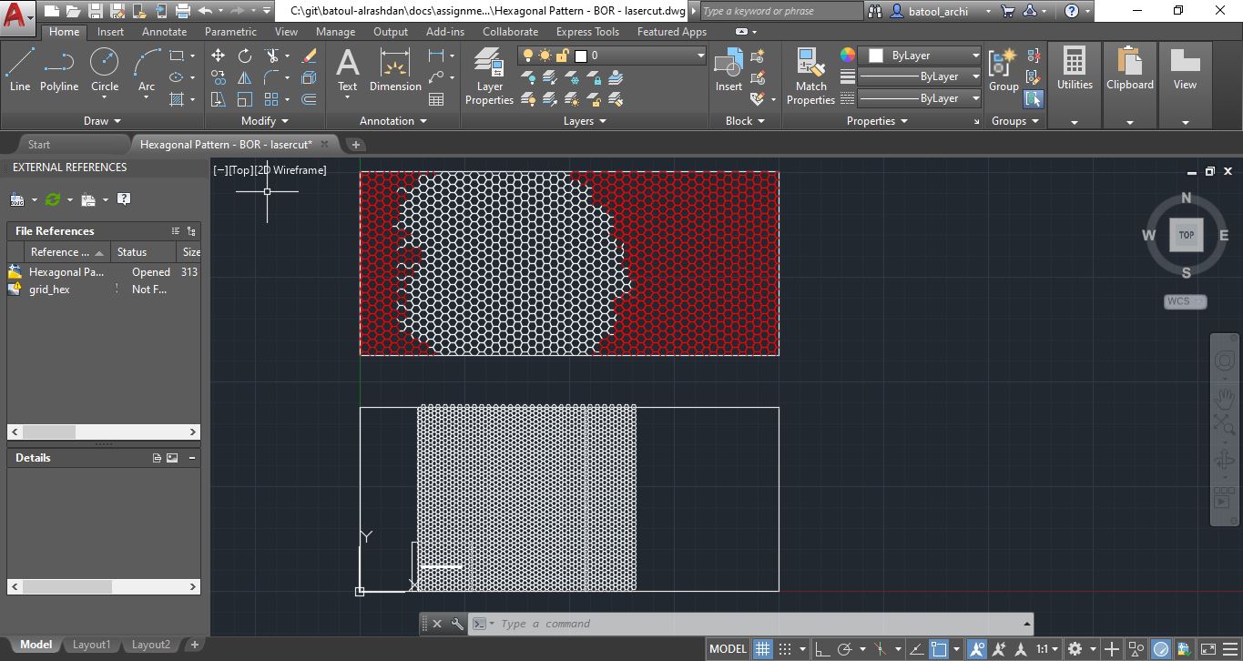 here i was trying to create hexagonal grid for Wildcard week 17 to laser cut for wood textile but im an architect so i previously know how to use autocad!
wasn’t parametric i just created hexagon and array to repeat it alone the rectangular boarder for the shelf i wanted to create or furniture piece which was 50*20 cm…
here i was trying to create hexagonal grid for Wildcard week 17 to laser cut for wood textile but im an architect so i previously know how to use autocad!
wasn’t parametric i just created hexagon and array to repeat it alone the rectangular boarder for the shelf i wanted to create or furniture piece which was 50*20 cm…
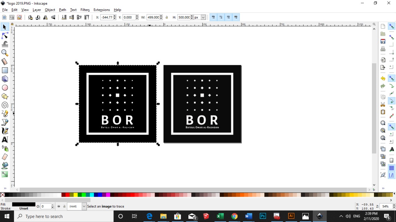
Inkscape
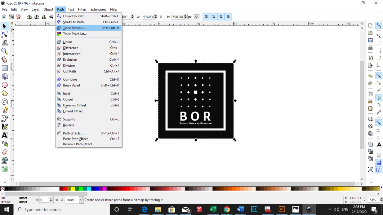
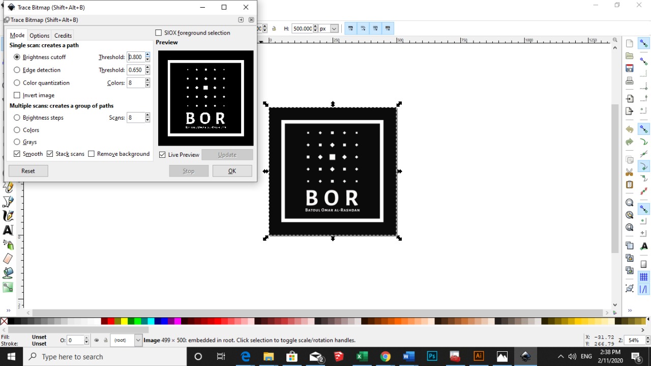
Here i wanted to test and compare the tracing of both Inkscape VS. Adobe Illustrator to transform from pixels to vectors (where makes you able to cut through CNC machines)
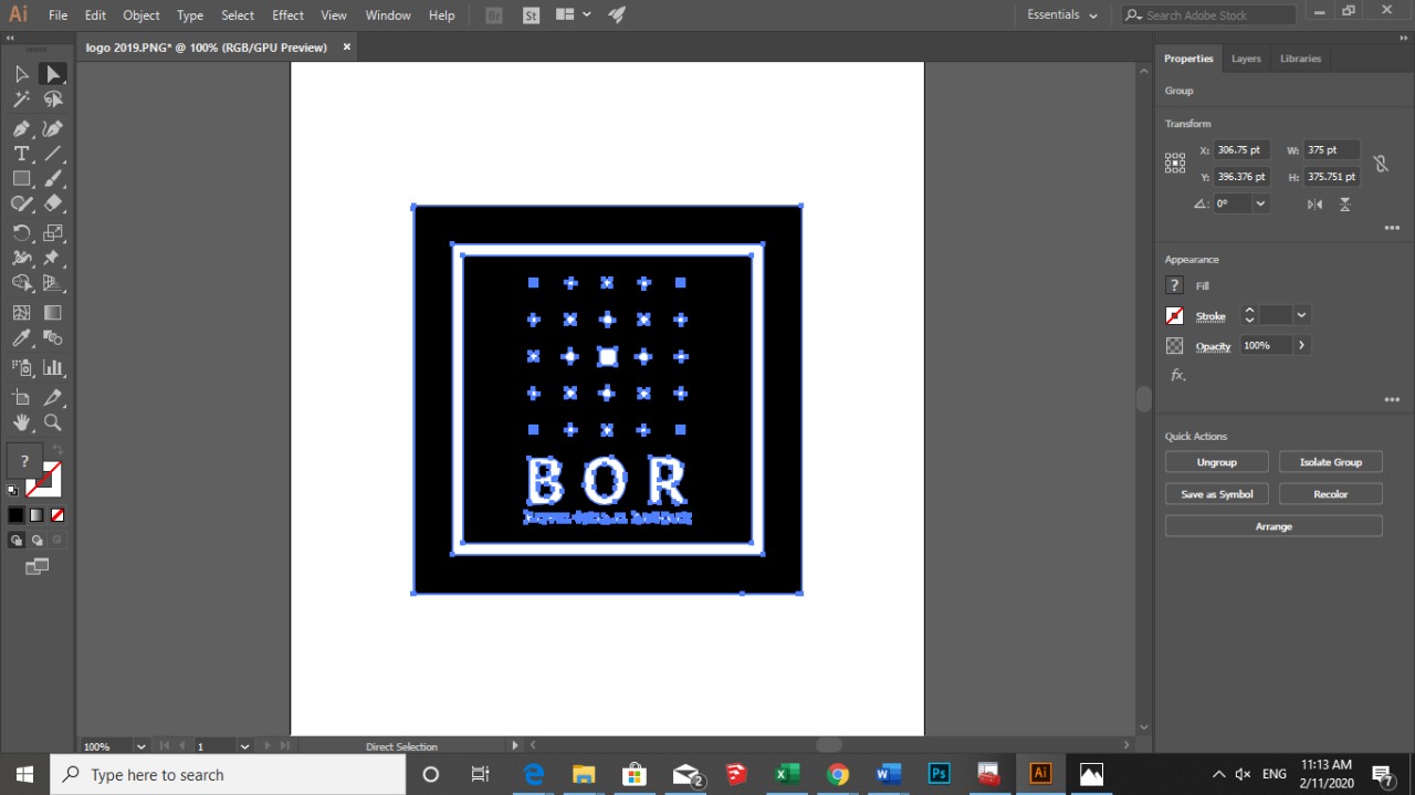
Adobe Illustrator
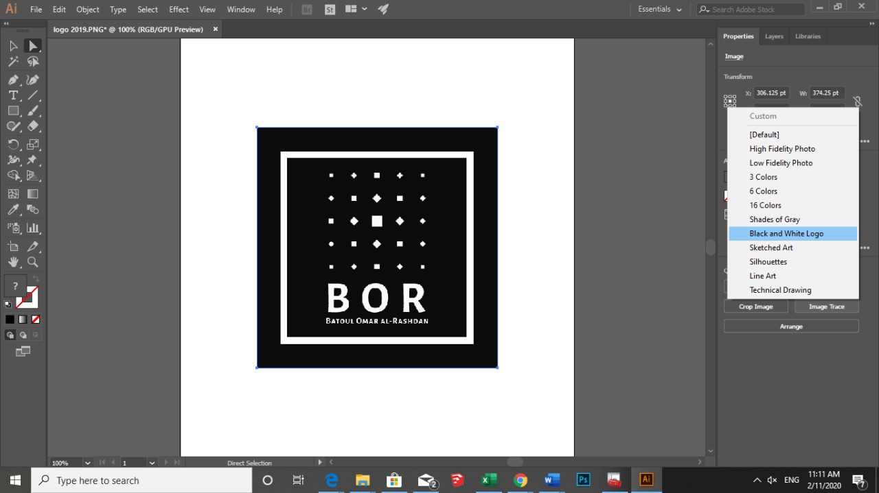
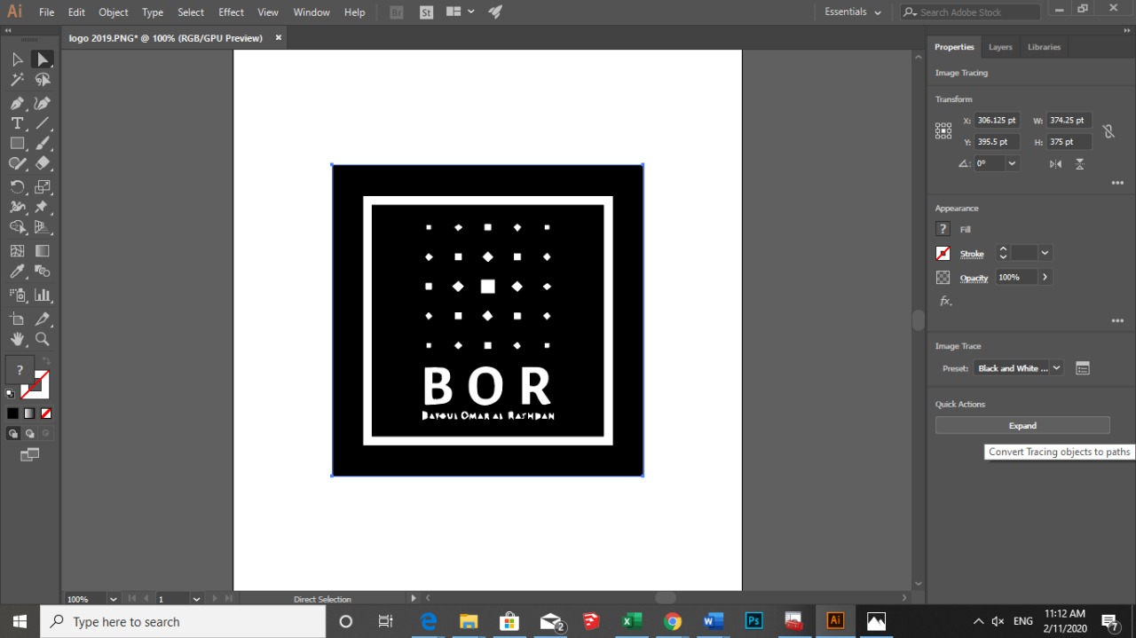
Choose Window > Image Trace or switch to the Tracing workspace to open the Image Trace panel, and do one of the following:
Choose one of the default presets by clicking the icons on top of the panel. For details, see Specify tracing options | Preset.
Choose a preset from the Preset drop-down menu.
Specify the tracing options. For details, see Specify tracing options.