8. Embedded programming
The Dassault Systemes Fablab, like many around the world, shut down after the last session due to the COVID-19 pandemic. I decided to fly down to Dallas to be with my sister during the shutdown. We were mailed two lab kits to work with at home. I tried to program my board that I made two weeks ago but to no avail. However, I did get it to blink that week. You can check it out over here.
I started off by playing around with the arduino and getting it to blink and fade some LEDs on a breadboard. Towards the end of the week I was able to use the arduino to program a keypad and a servo motor to function as a locking mechanism. Hopefully I can use this towards my final project.
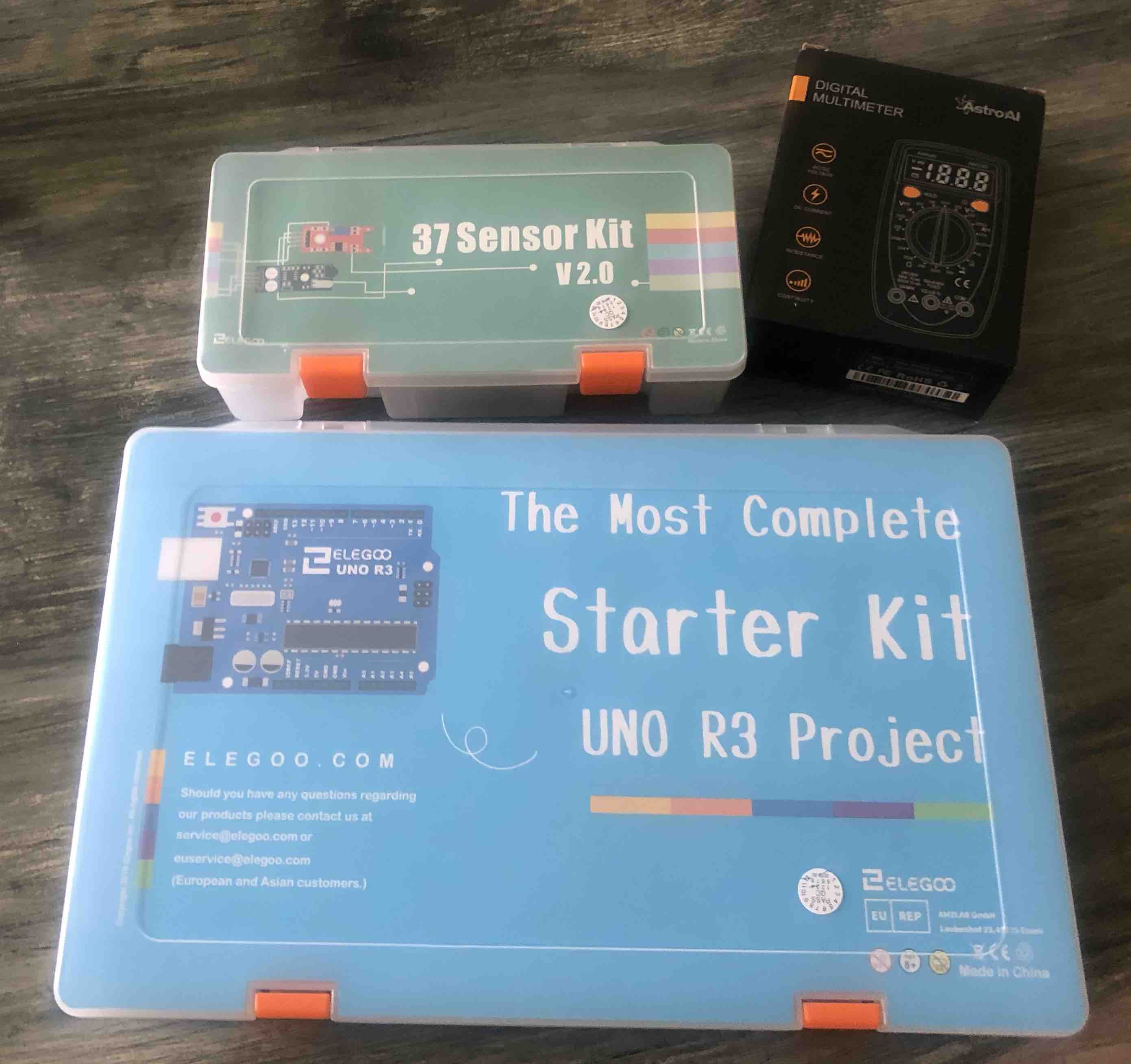
Packages are here! Lab for the next month or so:

|
|
Key Terms and Useful Knowledge
Lecture Notes
This week was very information heavy. I felt lost while listening to the lecture. I googled some of the terms after and I might have gotten even more lost. Therefore, I just typed some of the things that I thought might be useful in the future but I hadn’t fully grasped yet. After all, there is only so much information you can absorb in a week. :(
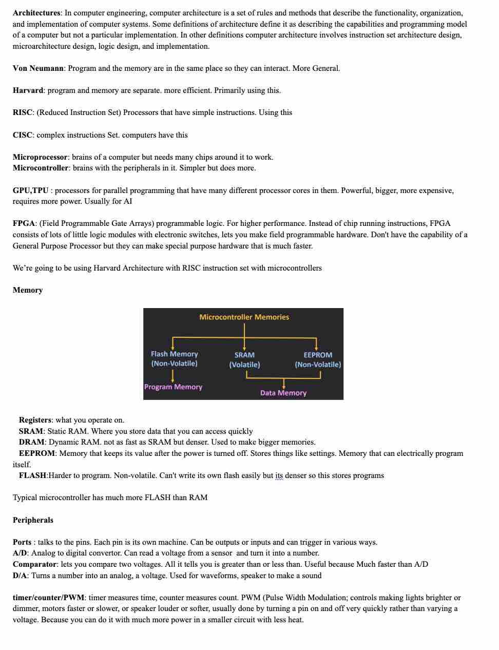
Here is an overview of my notes from lecture:

Arduino Notes
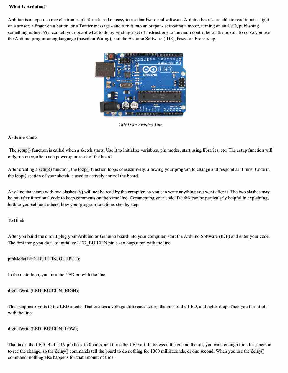
Since I will be working a lot with an Arduino board for the next few weeks, I thought I would try to get to know about it a little more. Here is some information that I got from the Arduino website:
Reading a Data sheet
Part of our individual assignment was to read the data sheet for a microcontroller. I decided to read the data sheet for a ATTiny44 here. Since it is about 500 pages long, I skimmed through it. Here are some takeaways:
- High Performance, Low Power AVR® 8-Bit Microcontroller
- 2K/4K Bytes of In-System, Self-Programmable Flash Program Memory
- 128/256 Bytes of In-System Programmable EEPROM
- 128/256 Bytes of Internal SRAM
- One 8-Bit and One 16-Bit Timer/Counter with Two PWM Channels
- 10-bit ADC
- Programmable Watchdog Timer with Separate On-chip Oscillator
- On-Chip Analog Comparator
- Universal Serial Interface
- Low Power Idle, ADC Noise Reduction, Standby and Power-Down Modes
- Enhanced Power-on Reset Circuit
- On-Chip Temperature Sensor
- Operating Voltage:1.8 – 5.5V
- Industrial Temperature Range: -40°C to +85°C
Pin configuration of ATTiny44:

ATiny44 Architecture:

Programming
Arduino as ISP
Before starting anything, I had to program the arduino board to be a programmer. I learned this after trying out the blink program and getting all these error messages:

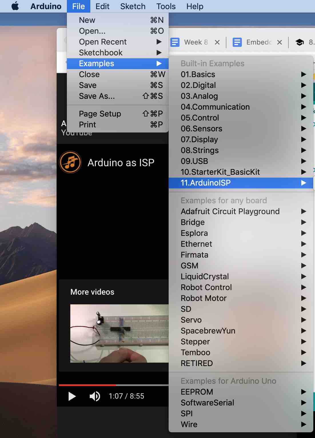
Setting it up to be a programmer was fairly easy. I followed along this tutorial. All you have to do is go to Files -> examples -> ArduinoISP and run it.
Once it says done uploading, the arduino is now a programmer.

Fade
Since I had tried out the blink program two weeks ago, I wanted to do something slightly different this week. So I tried out the built-in fade program on arduino. I followed this tutorial.
This is the breadboard set-up:
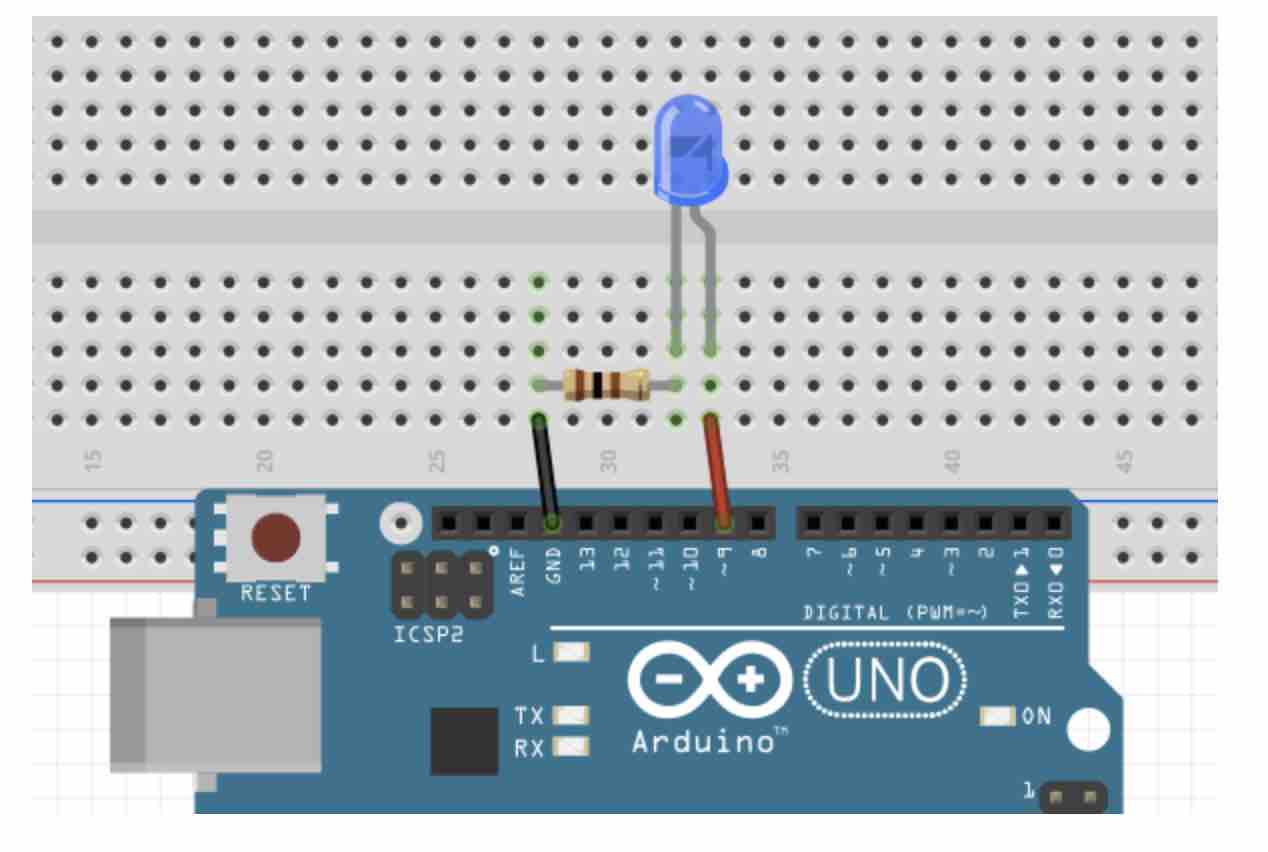
I connected it to my USB port and ran the built-in code. To fade it uses Pulse Width Modulation. This is the Fade Code:
int led = 9;           // the PWM pin the LED is attached to
int brightness = 0;    // how bright the LED is
int fadeAmount = 5;    // how many points to fade the LED by

// the setup routine runs once when you press reset:
void setup() {
  // declare pin 9 to be an output:
  pinMode(led, OUTPUT);
}

// the loop routine runs over and over again forever:
void loop() {
  // set the brightness of pin 9:
  analogWrite(led, brightness);

  // change the brightness for next time through the loop:
  brightness = brightness + fadeAmount;

  // reverse the direction of the fading at the ends of the fade:
  if (brightness <= 0 || brightness >= 255) {
    fadeAmount = -fadeAmount;
  }
  // wait for 30 milliseconds to see the dimming effect
  delay(30);
}
I ran it and it works!
Sequential Blinking
After the fade exercise, I decided to play around with multiple LED lights. I found this tutorial pretty helpful.
This is the code for the sequential blinkling:
int LED1 = 13;
int LED2 = 12;
int LED3 = 11;

void setup() {
   pinMode(LED1, OUTPUT);
   pinMode(LED2, OUTPUT);
   pinMode(LED3, OUTPUT);
}


void loop() {
  digitalWrite(LED1, HIGH);    // turn on LED1
  delay(200);                  // wait for 200ms
  digitalWrite(LED2, HIGH);    // turn on LED2
  delay(200);                  // wait for 200ms
  digitalWrite(LED3, HIGH);    // turn on LED3
  delay(200);                  // wait for 200ms
  digitalWrite(LED1, LOW);     // turn off LED1
  delay(300);                  // wait for 300ms
  digitalWrite(LED2, LOW);     // turn off LED2
  delay(300);                  // wait for 300ms
  digitalWrite(LED3, LOW);     // turn off LED3
  delay(300);                  // wait for 300ms before running program all over again
}
I ran it and it worked:
Keypad and Servo Motor
While going through several arduino projects I came across one that seemed very interesting and could work towards my final project. It was programming the keypad to control the servo motor thus simulating a locking mechanism. I tried one that askes for the passcode on the LCD screen. I didn’t get that far. I hope to tackle this next week.
This is the tutorial that I followed. It uses two LED lights, one red and one green. The red one shows that the mechanism is in locked position and the green one shows that it is open.
Components required:
- Arduino Uno
- Breadboard
- Servo Motor
- Keypad
- Two LEDs
- Two 220 ohm resistors to protect the LEDs
- Few jumper wires
Assembling
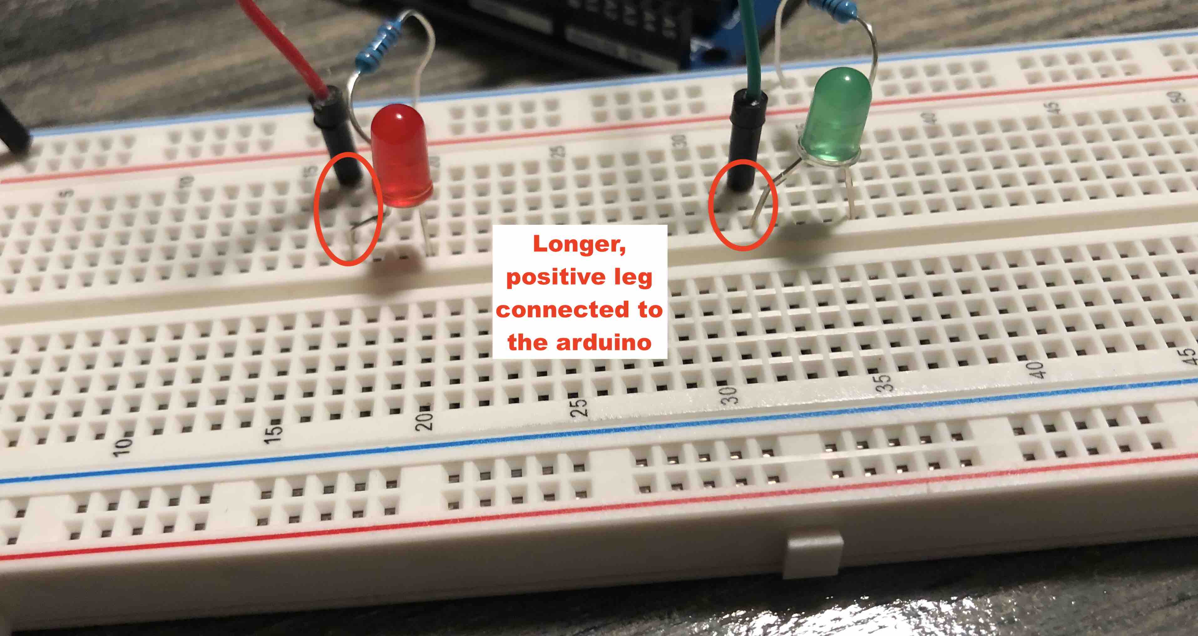
1) Put the LEDs on the breadboard. Remember that the longer leg is the postive end so make sure that the longer leg is connected to the arduino.
2) Connect the resistors to the LEDs. Insert one end of the resistor on the same connection as the shorter leg of the LED and the other end to the negative rail of the breadboard (ground).
3) Connect the negative rail of the breadboard to the GND port on the arduino.
4) Connect the LEDs to the arduino. I connected the red LED to pin no 12 and the green one to pin no 13.
5) Connect the servo motor to the arduino. The servo motor comes with 3 wires: brown, red, and orange. Brown is ground, red is the power and orange is the signal wire. Connect the brown one to GND on the arduino, the red one to 5V port, and the orange one to pin 11.
6) Connect the keypad to the arduino. Connect the first wire to pin no 2 on the arduino, second wire to pin no 3, third wire to pin no 4, fourth wire to pin no 5, fifth wire to pin no 9, sixth wire to pin no 6, seventh wire to pin no 7, and the last wire to pin no 8.
Programming
Once the breadboard and the other components are assembled, it is time to program the board. Here is the code:
#include <Servo.h>
#include <Keypad.h>
Servo ServoMotor;
char* password = "753"; // change the password here, just pick any 3 numbers
int position = 0;
const byte ROWS = 4;
const byte COLS = 4;
char keys[ROWS][COLS] = {
{'1','2','3','A'},
{'4','5','6','B'},
{'7','8','9','C'},
{'*','0','#','D'}
};
byte rowPins[ROWS] = { 8, 7, 6, 9 };
byte colPins[COLS] = { 5, 4, 3, 2 };
Keypad keypad = Keypad( makeKeymap(keys), rowPins, colPins, ROWS, COLS );
int RedpinLock = 12;
int GreenpinUnlock = 13;
void setup()
{
pinMode(RedpinLock, OUTPUT);
pinMode(GreenpinUnlock, OUTPUT);
ServoMotor.attach(11);
LockedPosition(true);
}
void loop()
{
char key = keypad.getKey();
if (key == '*' || key == '#')
{
position = 0;
LockedPosition(true);
}
if (key == password[position])
{
position ++;
}
if (position == 3)
{
LockedPosition(false);
}
delay(100);
}
void LockedPosition(int locked)
{
if (locked)
{
digitalWrite(RedpinLock, HIGH);
digitalWrite(GreenpinUnlock, LOW);
ServoMotor.write(11);
}
else
{
digitalWrite(RedpinLock, LOW);
digitalWrite(GreenpinUnlock, HIGH);
ServoMotor.write(90);
}
}
The password is set to 753. In the video below you can see the motor turn 90 degrees when the password is entered and the green LED turn on:
Conclusion
Although I learned a lot of arduino related things this week, there is still a lot to do. I need to learn to code better and add a microcontroller to the breadboard so that it remembers the program.
2022 continuation
Since I now have access to a lab and my hello world board. Suhas, our instructor, gave a virtual class on this topic that was recorded by Take. I watched the lecture and here are some key takeaways:
Two main architectures are RISC and CISC. Here is the difference between the two:
| RISC | CISC |
|---|---|
| Reduced Instrumentation Set Computing | Complex Instrumentation Set Computing |
| Under Harvard Architecture | Under Von Neuman Architecture |
| Newer model | Older Model |
Differnce between microprocessor and microcontroller
| Microprocessor | Microcontroller |
|---|---|
| Peripherals are outside the motherboard: for example in a laptop, the RAM, SRAM… are all outside. | Periopherals are inside. |
| Executes multiple instructions at the same time | Fixed operations |
| Suited for complex operations | Suited for cheper, simpler operations |
| Much more memory | Less memory |
One of the important variables in a microcontroller is memory. There are different types of memory in a microcontroller.
- Register is the memory inside a microcontroller.
- SRAM/DRAM: hold temporary data. Higher RAM means better performance. Once shut down or power switched off, all the RAM data is erased.
- EEPROM: Stands for Electronically Erasable Programmable Random Read Only Memory. This is comparable to loading a program to an Arduino board. Arduino stores it in EEPROM. Disconnecting and reconnecting the Arduino to power doesnt erase the program. However, uploading another program erases the first one.
- FLASH: Programs, strings and libraries go here.
- If you want your application to be fast, check SRAM. If you have a big program, you need to check the EEPROM and FLASH memory.
After consultation with Fran,I decided to use the Atmega328P for my final project.
### Programming hello world board with FabISP
I decided to program the Hello World board I had to first blink and then to fade. You have to be weary that the number you put into the arduino code is the arduino pin, not the pin on the microcontroller. This was the first mistake I made.
The pin that was connected to my LED is pin 6 on the microcontroller so on the arduino I had to put pin no 7 on aruduino IDE. Care also has to be taken to ensure that the connectors on the FabISP match the ones on the hello world board.
Here it is in action:
Assessment guide
Documented what you learned from reading a microcontroller datasheet.
Described the programming process/es you used
Included your source code
Programmed your board
Included a short ‘hero video’ of your board
Linked to the group assignment page