12. Interface and application programming
This was a very programming heavy week. In lecture we went over the different languages we can use and their pros and cons. Neil strongly recommended Python so I decided to go with that. The learning curve was huge but nothing beats the satisfaction of finally getting your code to work.
Individual Assignment
This week’s assignment was to write an application that interfaces a user with an input and/or output device that we made. Since we still do not have access to the lab, I got it to interface with my arduino board. Initially, I was little ambitious and tried to get the python code to control the display on a LCD screen. The GUI turned out okay but there was no communication between the GUI and the LCD. Therefore, I stepped back and decided to create a GUI that acts as a digital switch for a LED on my arduino board. This worked.
Background
I do not have much experience with coding. The closest I have come to it prior to this course is a MATLAB class that I took for a semester in college. I do not remember anything at all from that class so I consider myself new to the coding world. To start off the class I googled a few tutorials for an introduction to Python.
I found this video on how to check if python is installed on your computer. I went to my terminal and checked. This is what I got:

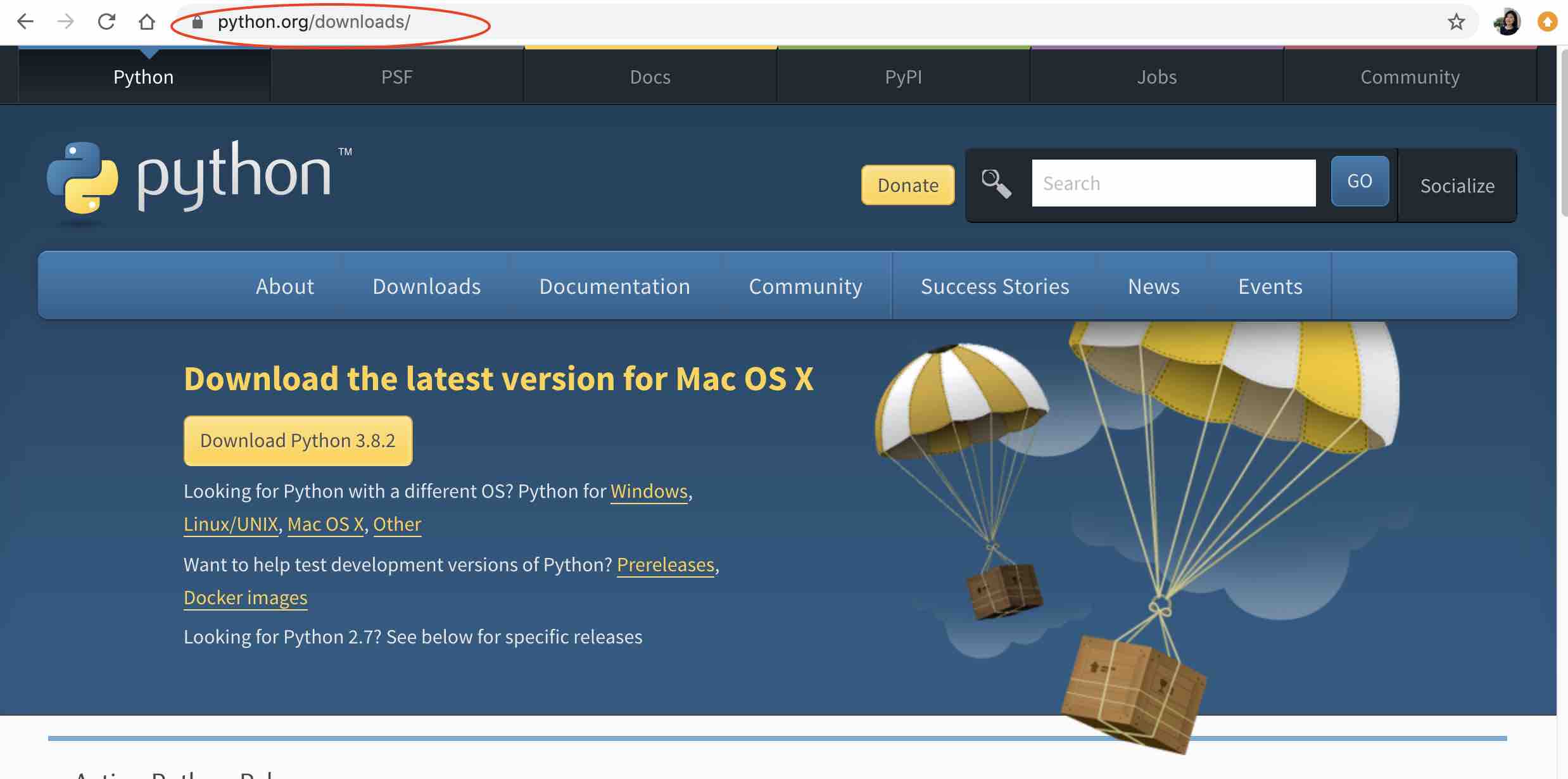
Python was already installed on my computer. I later learned that this is becuase it is native to macs. However, I still had to install Python IDLE to run code. For this I went to the Python website and downloaded the latest version. The website automatically recommends the latest version for your devices.
After IDLE got downloaded, I opened it and tried to run a basic code that I found online. However, I could not find the run button.
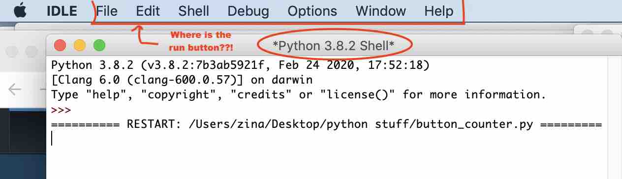
This is the first basic trouble that I ran into. I thought that it was a mac problem since all the videos that I had watched up to this point worked on windows. I googled a python tutorial on mac OS and found this video. I finally figured out that a new file has to be created for a code to run. The shell page is the program page and closing it will kill the program that is currently running. Okay, create new file and then run the code, not directly from the first page. check.

To check if codes were really running on my mac, I ran a code that creates a GUI with a button counter and it worked!
Here is a short video of the button counter.
The world of Tkinter
Now that I know my mac is okay with running Python codes, I decided to watch a lengthy tutorial on creating my own GUI. This youtube tutorial was super helpful with explaining the basics. Although the video is in Hindi, I was able to understand thanks to my many hours of watching Bollywood movies and television shows. My notes while watching the video is on this google doc.
After the tutorial was done, I was able to create entryboxes, radio buttons, comboboxes, change color on some of the texts, and store the entry in a .txt file. Here is a video of the GUI:
This is the code for it:
import tkinter as tk
from tkinter import ttk
win = tk.Tk()
win.title('Zina GUI')

name_label=ttk.Label(win, width=16,text='Enter your name here')
name_label.grid(row=0,column=0)

age_label=ttk.Label(win,width=16,text='Enter your age here')
age_label.grid(row=1,column=0)

gender_label=ttk.Label(win,width=20,text='select your gender here')
gender_label.grid(row=2,column=0)

name_var=tk.StringVar()
name_entrybox= tk.Entry(win, width= 16, textvariable = name_var)
name_entrybox.grid(row=0, column=1 )
name_entrybox.focus()

age_var=tk.StringVar()
age_entrybox= ttk.Entry(win, width= 16, textvariable = age_var)
age_entrybox.grid(row=1, column=1)

gender_var=tk.StringVar()
gender_combobox= ttk.Combobox(win,width=16, textvariable=gender_var,state='readonly')
gender_combobox['values']=('Male','Female','other')
gender_combobox.grid(row=2,column=1)
gender_combobox.current(0)

usertype=tk.StringVar()
radiobtn1=ttk.Radiobutton(win, text='Student',value='Student',variable=usertype)
radiobtn1.grid(row=3,column=0)

radiobtn2=ttk.Radiobutton(win, text='Teacher',value='Teacher',variable=usertype)
radiobtn2.grid(row=3,column=1)

checkbtn_var=tk.IntVar()
checkbtn=ttk.Checkbutton(win, text='subscribe to our newsletter', variable=checkbtn_var)
checkbtn.grid(row=4,columnspan=3)

def action():
    username=name_var.get()
    userage = age_var.get()
    print(f'{username} is {userage} years old')
    user_gender=gender_var.get()
    user_type=usertype.get()
    if checkbtn_var.get()==0:
        subscribed ='NO'
    else:
        subscribed = 'YES'
    print(user_gender,user_type,subscribed)

    with open('file.txt','a') as f:
        f.write(f'{username},{userage},{user_gender},{user_type},{subscribed},\n')

    name_entrybox.delete(0,tk.END)
    age_entrybox.delete(0,tk.END)

    name_label.configure(foreground='#991E1E')
    submit_button.configure(foreground='Blue')

submit_button = tk.Button(win, text='Submit',command=action)
submit_button.grid(row=5, column=0)

win.mainloop()
LCD with Python
After the last tutorial I felt pretty confident. Therefore, I decided to try to get python to create a GUI that controls the display on a LCD screen. I took the inspiration for this from this students page.
First, I set up my arduino board. Here are the things that you need:
- 16x2 LCD screen
- Arduino Uno
- Breadboard
- Potentiometer
- Jumper wires
This is a sketch of how the LCD is connected:

This is the code for arduino that was uploaded:
include <LiquidCrystal.h> // includes the LiquidCrystal Library
LiquidCrystal lcd(12, 11, 5, 4, 3, 2); // Creates an LC object. Parameters: (rs, enable, d4, d5, d6, d7)

String writestring = "";

void setup() {
 lcd.begin(16,2); // Initializes the interface to the LCD screen, and specifies the dimensions (width and height) of the display
 Serial.begin(9600);

 lcd.print("Hello Fabacademy");
}

void loop() {
 if (Serial.available()) {
  delay(100);
  while (Serial.available() > 0) {
    writestring += char(Serial.read());
  }
  lcd.clear();
  lcd.print(writestring);
  writestring = "";
 }
}
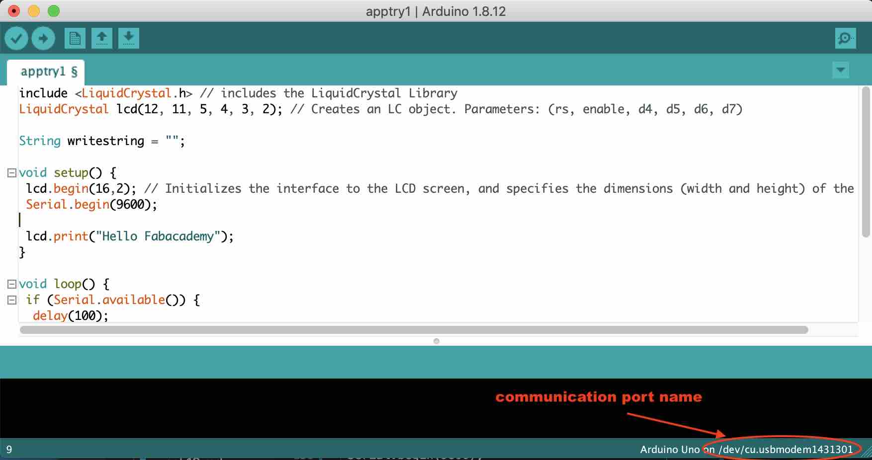
The communication port name can be found on the bottom right side of the arduino page.
This is the python code:
from tkinter import *
from time import sleep
import serial

ser=serial.Serial('/dev/cu.usbmodem1431301',9600)
sleep(2)

root = Tk()
top = Frame(root)   # Create frame to hold entrys
top.pack()          # Pack top frame
l1 = Label(top, text="Program the LCD")
l1.pack(side=TOP)

l2 = Label(top, text="Type LCD text")
l2.pack(side=LEFT)

e1 = Entry(top, bd=5)
e1.pack(side=LEFT)

l = Label(root)
def callback():
   ser.write(bytes(e1.get(),'utf-8'))

bottom = Frame(root)    # Create frame to hold button
bottom.pack()           # Pack bottom frame
b = Button(bottom, text="Click to send", command=callback)
b.pack()

root.mainloop()

ser.close()
The code was not recognizing the communication port. I thought that it might be a mac problem. Here is a picture of the error:
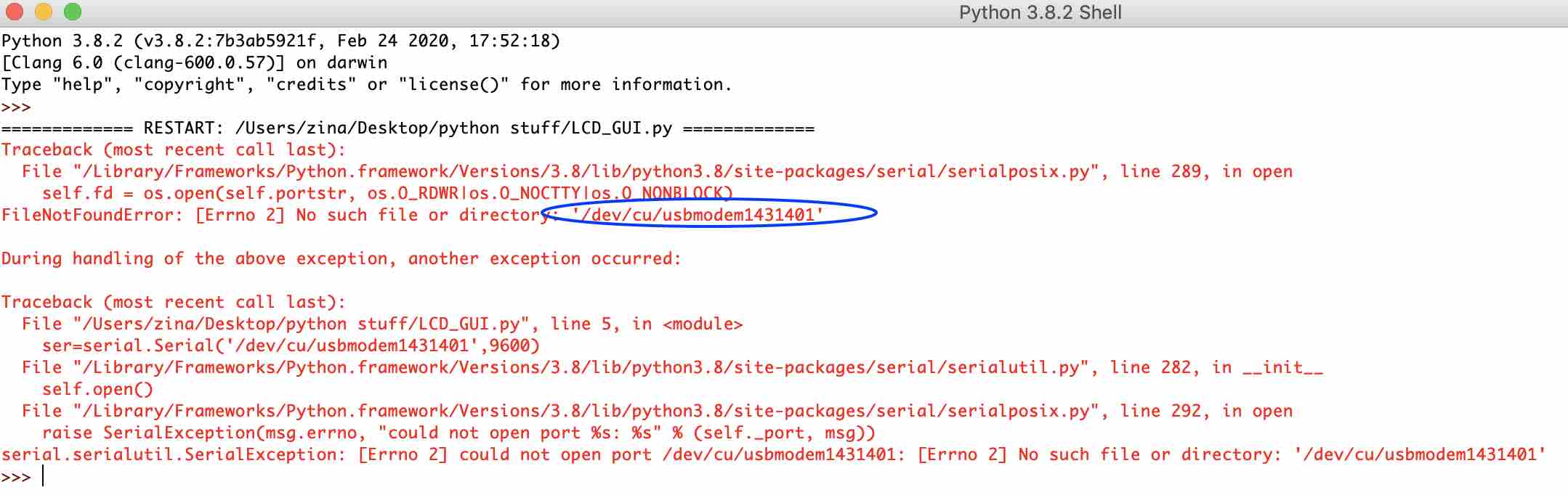
I cross checked the modem number a couple of times and even changed the USB port to make sure that was not the problem. On closer inspection, I realised that it was a typo… I had typed a back slash instead of a period. :/ Once I fixed the typo, the GUI was created but it failed to talk serially to the arduino. Here is a picture of the GUI:
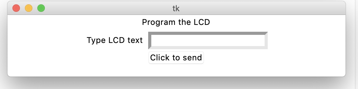
I was not able to debug this. I realised that I had been too ambitious so I decided to attempt a simple LED control GUI instead.
LED with Python
I found this video online on how to create a GUI on python that controls a LED on an arduino board. This tutorial was very simple and easy to follow along. In the tutorial, the LED is connected directly on the arduino without a breadboard. I decided to use a breadboard and pull-up resistor just to be safe.
Components required:
- Breadboard and jumper wires
- Arduino Uno
- LED
- 220 ohm resistor
This is the code for Arduino:
int led = 13;
char mydata=0;
// the setup routine runs once when you press reset:
void setup() {
  // initialize the digital pin as an output.
  pinMode(led, OUTPUT);
    Serial.begin(9600);
}


// the loop routine runs over and over again forever:
void loop() {

 mydata= int(Serial.read());


if (mydata=='1')
  digitalWrite(led, HIGH);   // turn the LED on (HIGH is the voltage level)

  if(mydata=='0')
  digitalWrite(led, LOW);    // turn the LED off by making the voltage LOW
}
This is the code for python:
import serial
import time
from tkinter import *


def led_on():
     arduinoData.write(b'1')


def led_off():
     arduinoData.write(b'0')


led_control_window= Tk()
btn=Button(led_control_window,text="led on",command=led_on)
btn2=Button(led_control_window,text="led off",command=led_off)
btn.pack()
btn2.pack()
arduinoData = serial.Serial('/dev/cu.usbmodem1431301',9600)
and it WORKS!
Hallelujah! Although this is pretty simple, I was ecstatic when it worked. It was a huge learning curve. To challenge myself, I want to try to upload a blink function next and try it out with multiple LEDs. But for now, I shall sleep.
2022
With access to a lab now, I decided to continue from where I left off in 2020. I designed a board using attiny1614 to get a start on my final project. I refered to the adrianino and made some changes to it. This is the schematic and the pcb board deisgn:

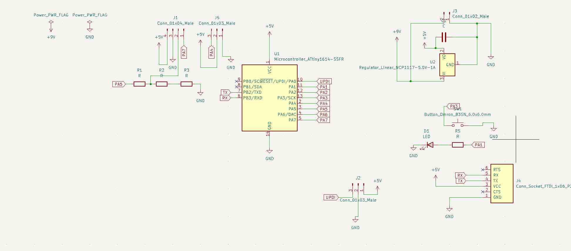
I designed the board to have a finger print sensor as the input and a servo motor as the output. It has a UPDI connectors to program the board, and FTDI connectors for data signal. I connected a LED to pin PA1 (8 on the arduino) to check programming errors. Therefore, I decided to try to control this LED with the python code.
Uploading the code
Since this is the first time that I am working with a FTDI programmer, it was a challenge but a good learning curve.
Initially I tried to program with the FTDI connector directly with to my board and it didnt work. I got this error:

I asked Suhas sir about this and he said that I need to make a board that converts the FTDI to UPDI. I milled Neils board to do this.
Neils board:

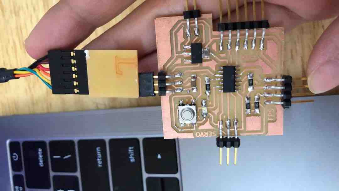
I milled and soldered the board and then tried to run the program.

Since the LED on the board is connected to PA1 on the attiny1614, this corresponds to pin 8 on the arduino.I made the changes to the code and ran it.
Arduino code:
int led = 8;
char mydata=0;
// the setup routine runs once when you press reset:
void setup() {
  // initialize the digital pin as an output.
  pinMode(led, OUTPUT);
    Serial.begin(9600
    );
}


// the loop routine runs over and over again forever:
void loop() {

 mydata= int(Serial.read());


if (mydata=='1')
  digitalWrite(led, HIGH);   // turn the LED on (HIGH is the voltage level)

  if(mydata=='0')
  digitalWrite(led, LOW);    // turn the LED off by making the voltage LOW
}
Python Code:
import serial
import time
from tkinter import *


def led_on():
     arduinoData.write(b'1')


def led_off():
     arduinoData.write(b'0')


led_control_window= Tk()
btn=Button(led_control_window,text="led on",command=led_on)
btn2=Button(led_control_window,text="led off",command=led_off)
btn.pack()
btn2.pack()
arduinoData = serial.Serial('/dev/cu.usbserial-FTC8GIBG',9600)
Programming setup:
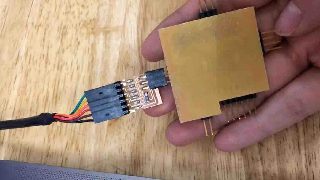
After I loaded the program it still wasnt working. Suhas sir said that after loading the program, I might had to connect the FTDI connector directly to the board and then try.

This still did not work. He told me to switch the RX and TX pins and then try. I did and it worked. Here is the video of it working: