Final Project
Brainstorm
For my final project, I had ideas that were either too ambitious or too simple. After Neil talked about the spiral development, I had a better understanding on how to approach the final project. After much contemplation and thinking, I finally decided on a bag that you can only open with a passcode or fingerprint.
Oftentimes, I find myself leaving my bag unattended in various public places, be it the gym, get-togethers, or cafes. So knowing that only I can open it, gives me a sense of peace and allows me to enjoy the moment more. I remember an acquaintance who lost all her money she was carrying in her bag while travelling when she went to use the restroom in an airplane.
Here is a VERY basic sketch of my idea. Im not the best artist out there so please bear with me:
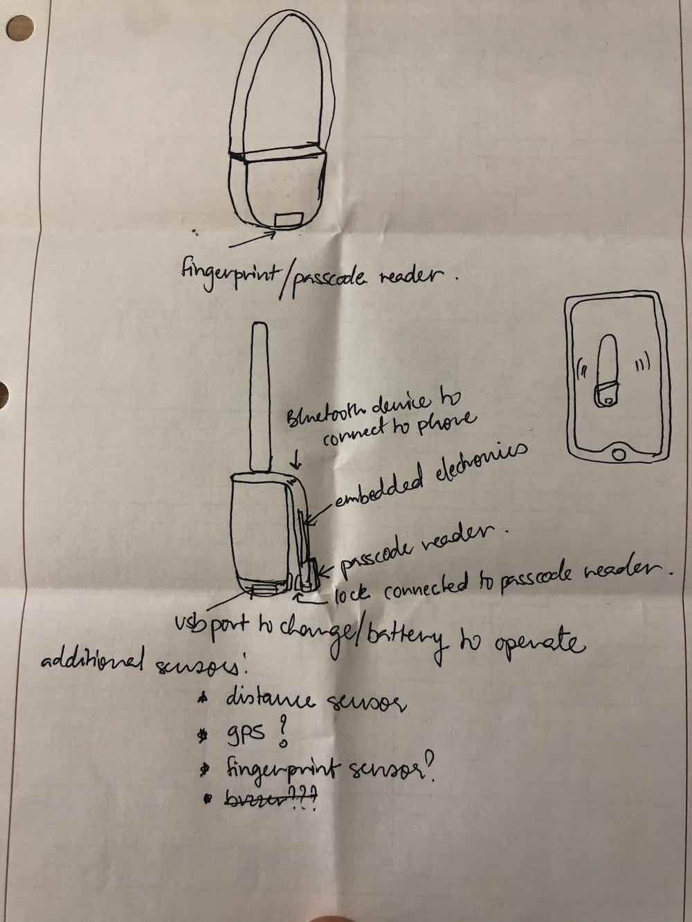
To initially use the bag, you would have to download an app that connects to your bag via bluetooth. Next, you set up your passcode on the app and then you’re ready to go! To add complexity to the project, I may explore adding gps to the bag or setting up an alert when it gets more than a certain distance away from you.
2D and 3D Modeling
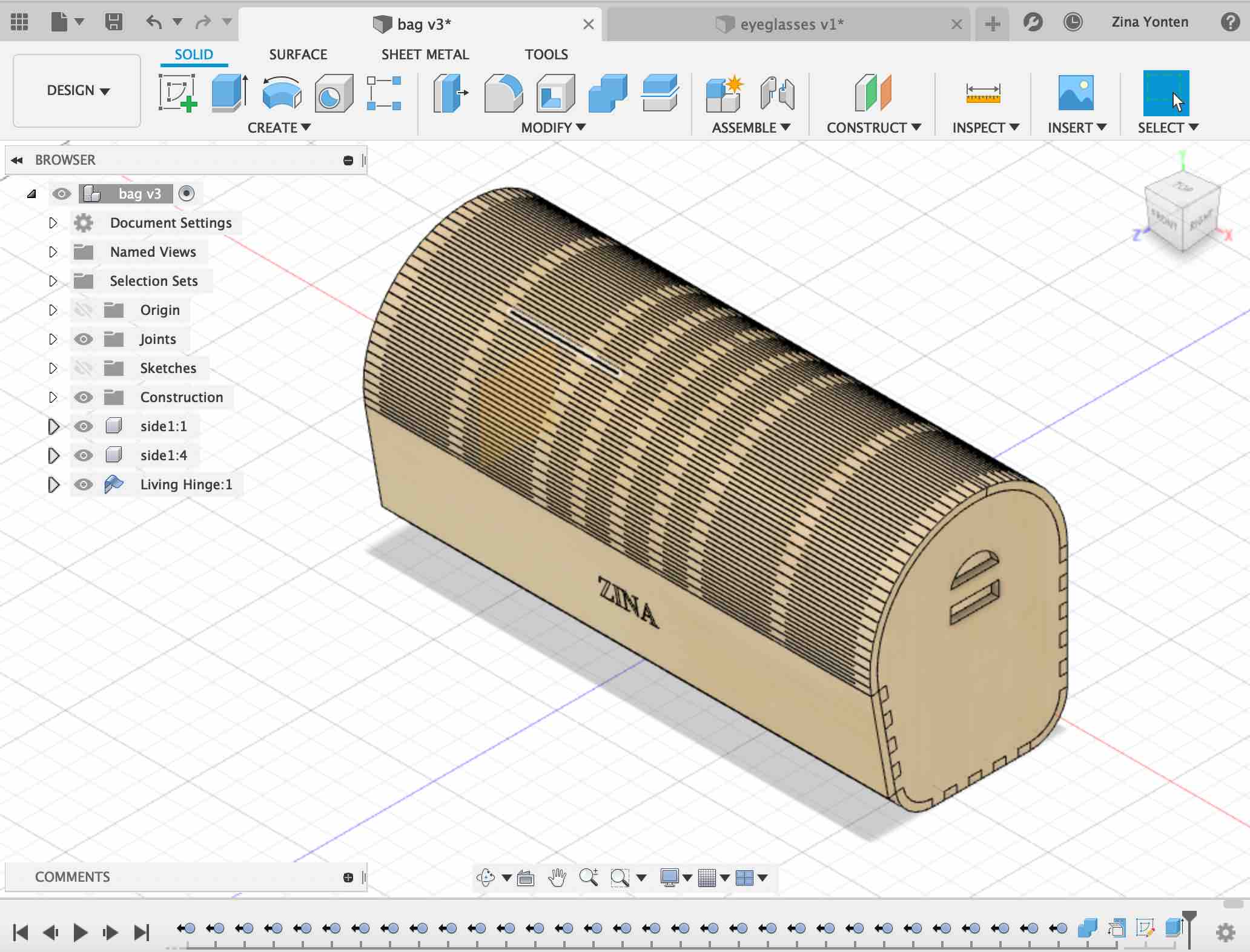
I designed an initial idea for the bag during week 3 of the course. Here is an overview of the design on Fusion360:
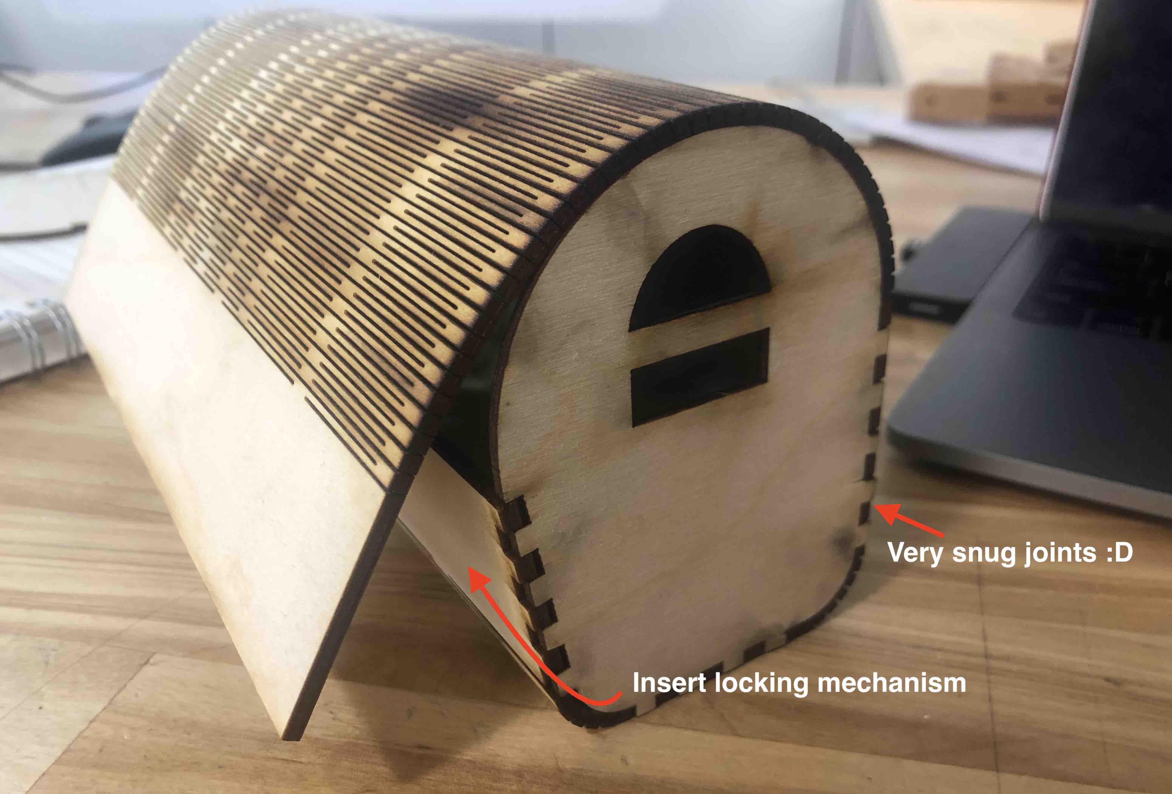
Here it is lasercut and assembled:
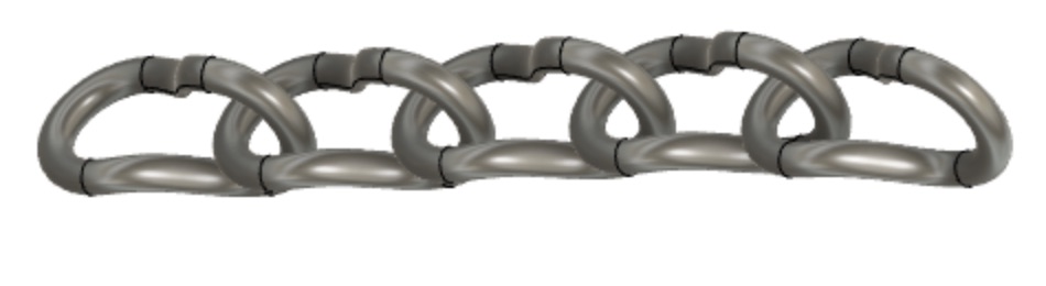
 This is the chainlink that I designed for the bag in week 5:
Here it is 3D-printed:
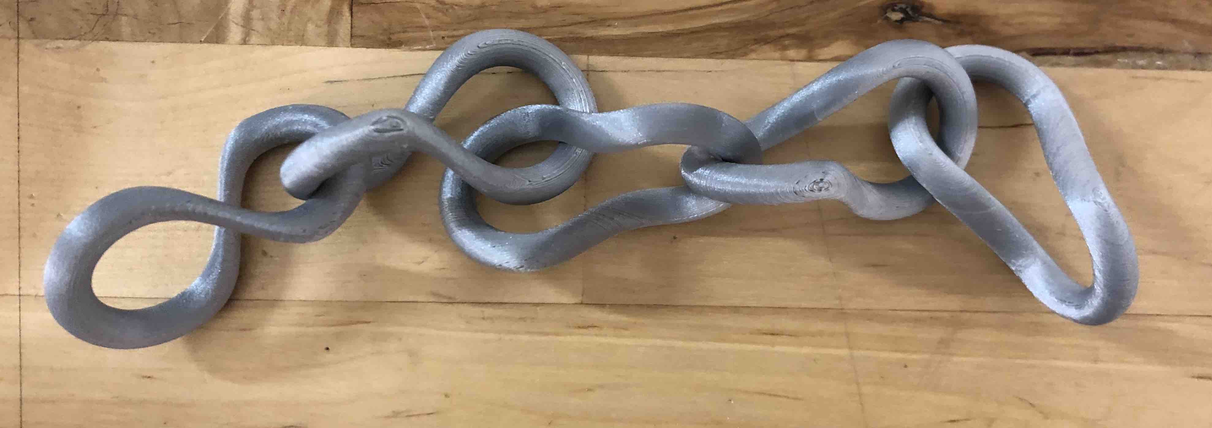
The chain links are bigger than I’d like them to be so I do need to scale them down. I also need to figure out how to attach them to the bag.
2022
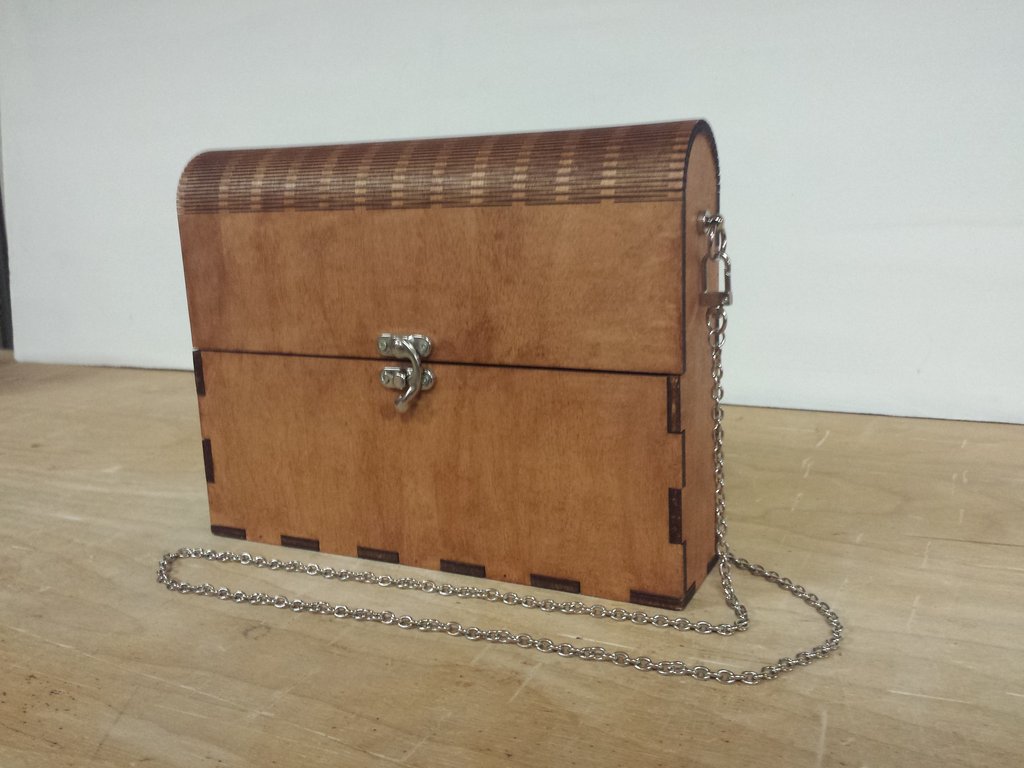
In 2022, I decided to redo the bag design. I looked up some laser cut bag designs for inspiration and found this really nice:
The design file for the bag is downloadable here.
I opened the .dxf file on inkscape and then made some change to design. This is the original file:
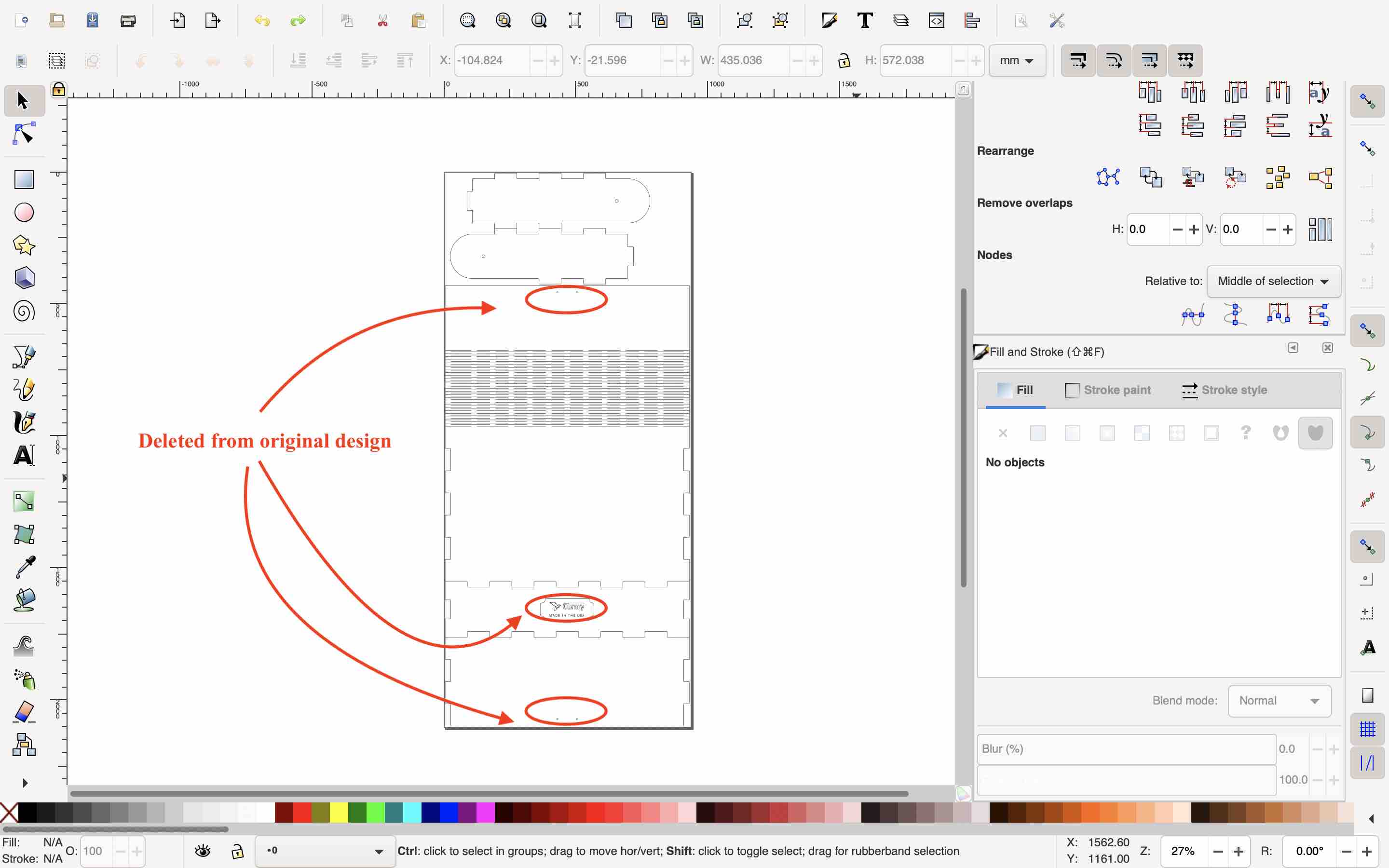
This is the edited design:
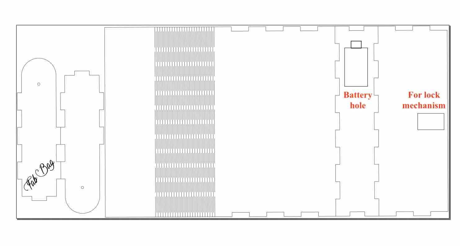
This is the bag cut:
Next I had a couple of things to design and 3D print. This is the list:
- Strap holder
- Battery holder and cover
- Lock mechanism
Strap Holder
I started with the strap holder since it is the simplest one. I measured the hole of on the side of the bag on inkscape. It comes to 3.437mm.
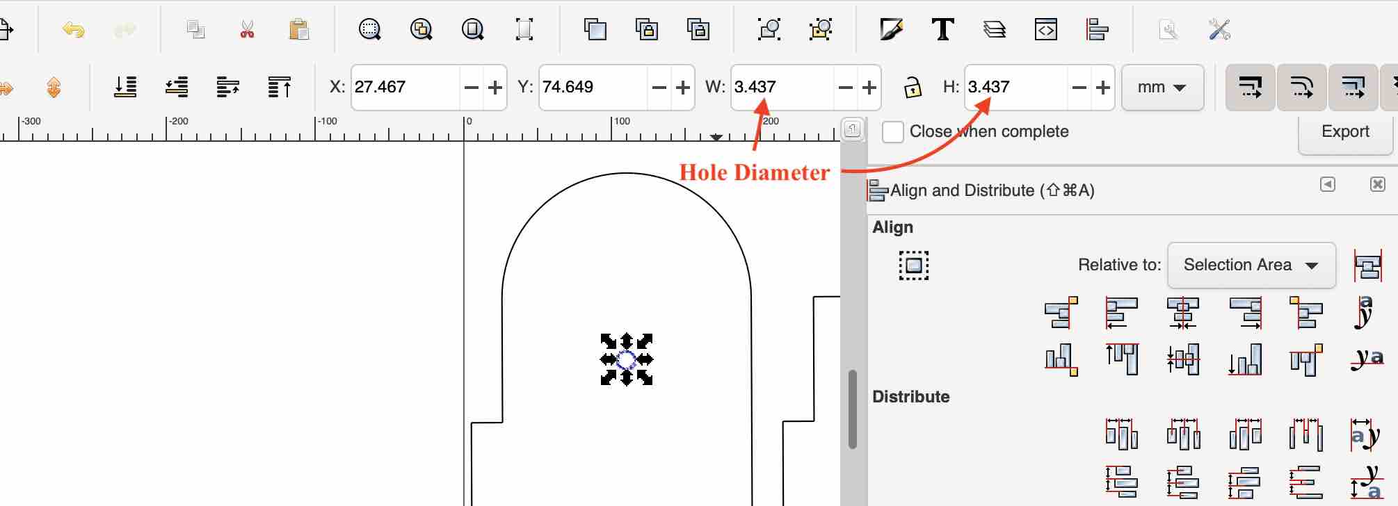
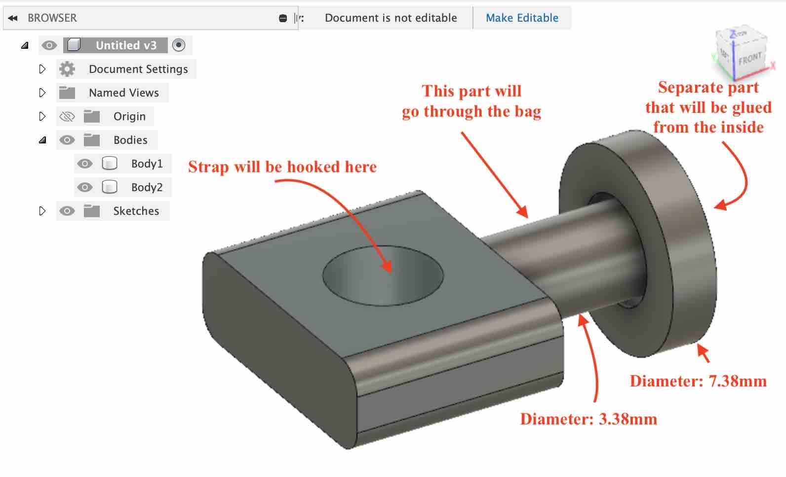
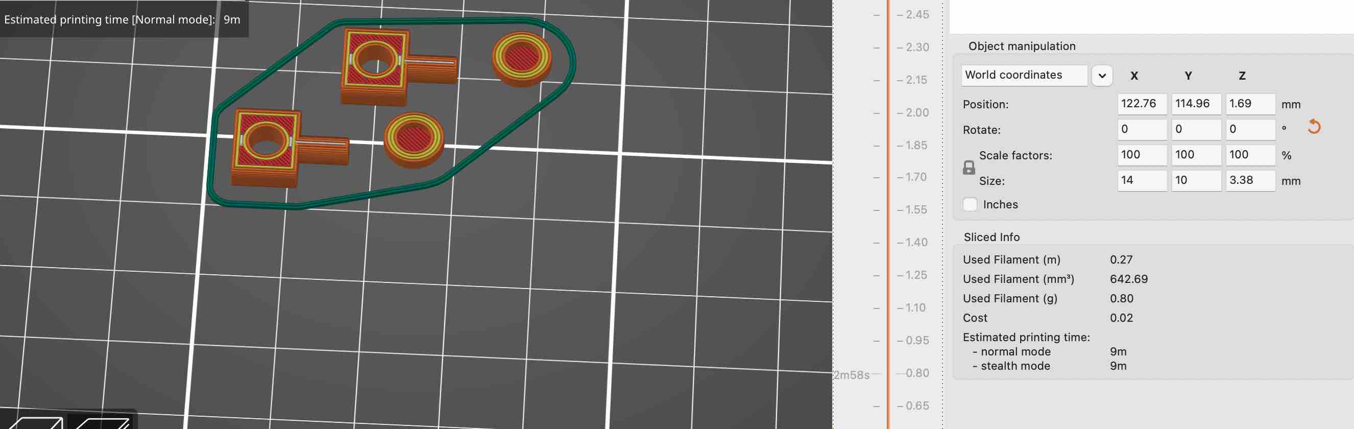
I wanted the strap holder to be snug in the hole but also be able to rotate around. So I made the diameter 3.38. I then designed a part with a hole where the strap can be hooked on. Finally there is a separate part that will glued on from inside the bag to hold it all in place. This is the design:
It took just 10 minutes to print:
It fit pretty well and I think it looks nice.

Battery Holder
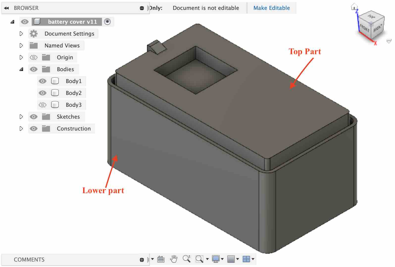
There is a 9V battery holder in the lab but it doesnt have a cover so I designed a full one for a more integrated look. I measured the width, breadth and height of the battery and then designed the holder with an offset of about 1mm. I designed the lower part to snap fit with the top one so that it will be fitted.
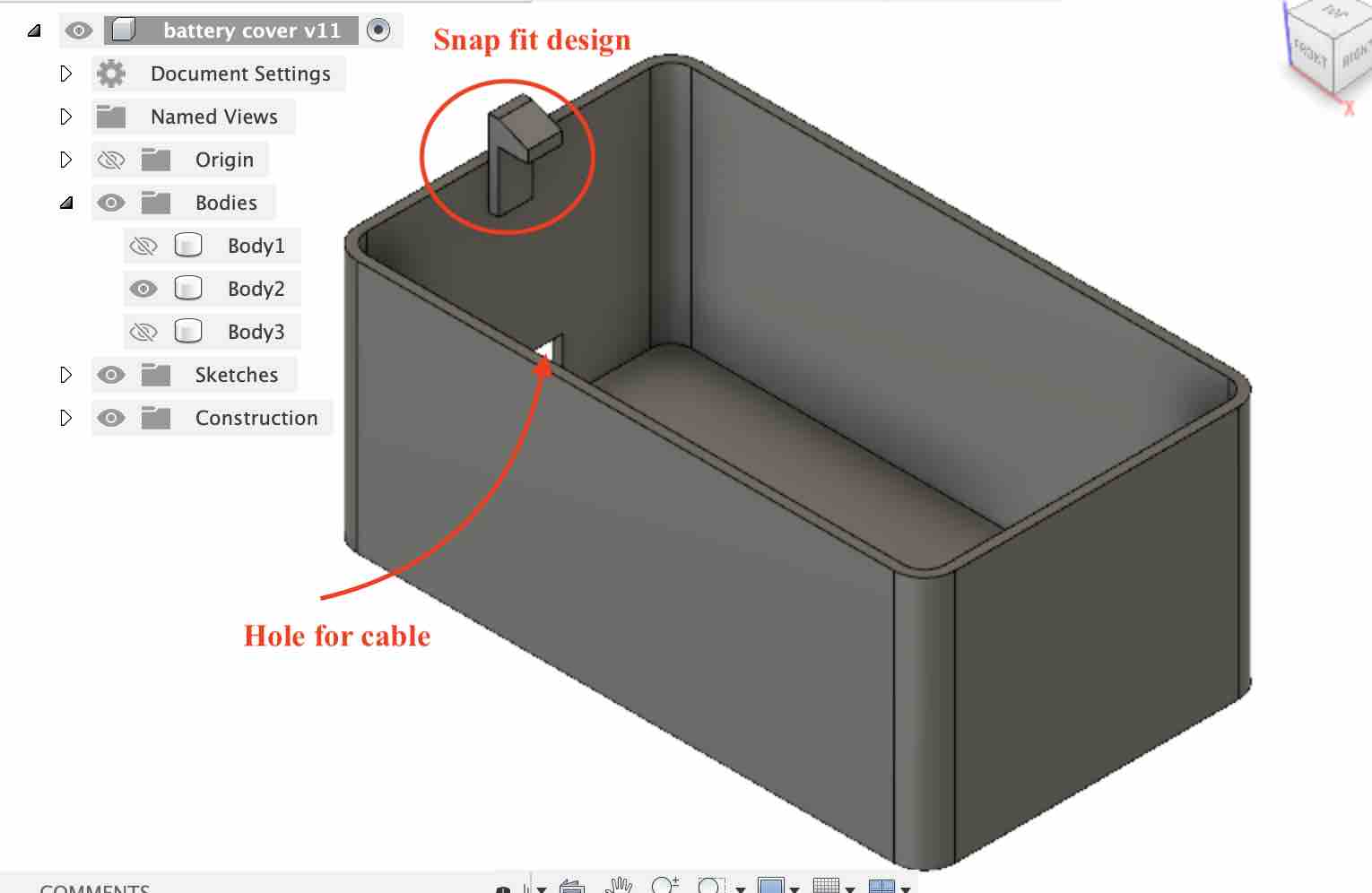
The top one is slightly smaller than the lower part since the lower part will be stuck on the laser cut wood and the top one will be slid through a hole in the wood. I designed a holder on the top part for grip while removing and putting it back.
I printed it out and it works pretty well:
Lock Mechanism
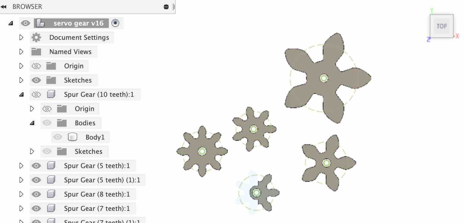
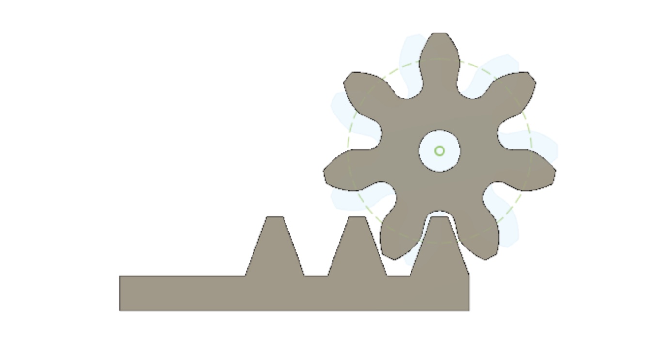
I had the toughest time with this design. I decided to go with a rack and pinion method. The pinion will be attached to the servo motor and the rack will act as the lock. I started on the pinion design using the spur gear add-in in Fusion360. I experimented with different settings and printed a few gears to see which one will work best.
Finally, this is the setting that worked the best for the servo:
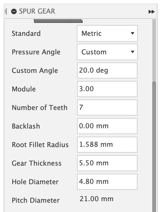
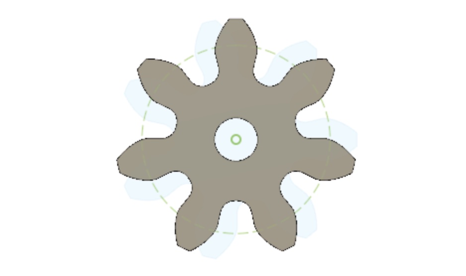
This is the gear:
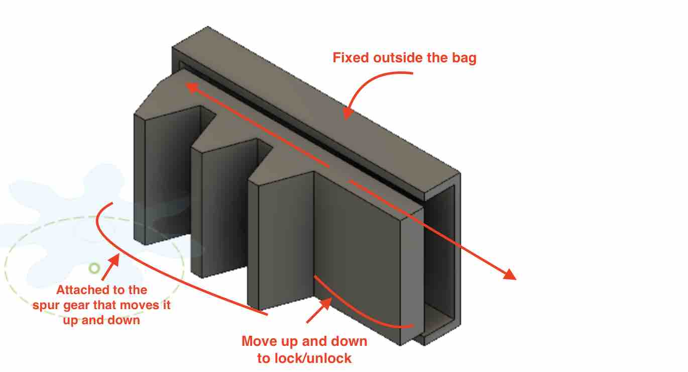
To design the rack, I checked some youtube video and found this one really useful. This is the finished product:
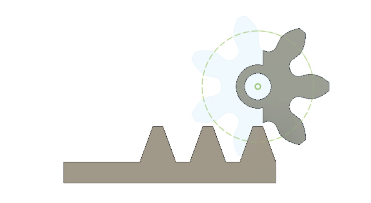
Finally, I trimmed the spur gear to make it less bulky on the inside of the bag. Since only 3 teeth will be used for, I trimmed the rest.
Finally, I designed a cover for the mechanism. The rack will be inside this cover and attached to the servo motor as well.
I printed the parts and assembled it. It works pretty well.
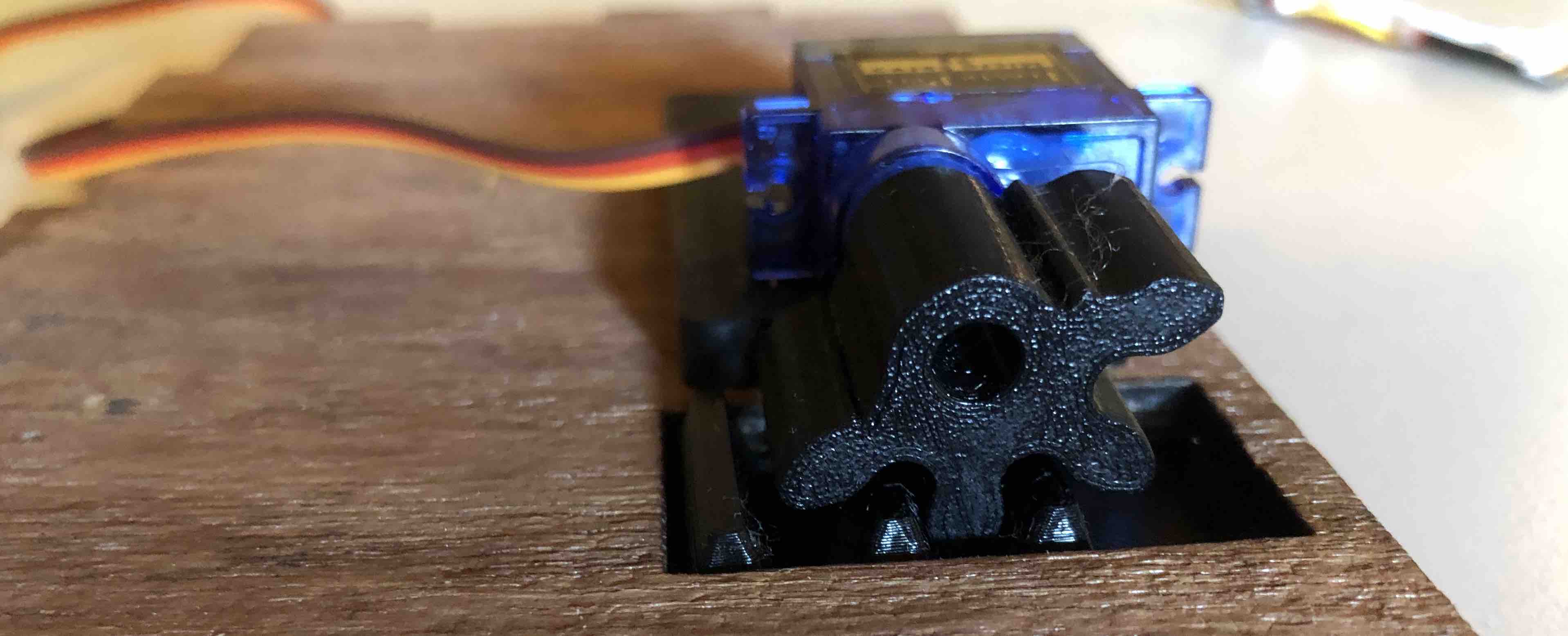
This is how the servo is attached on the bag:
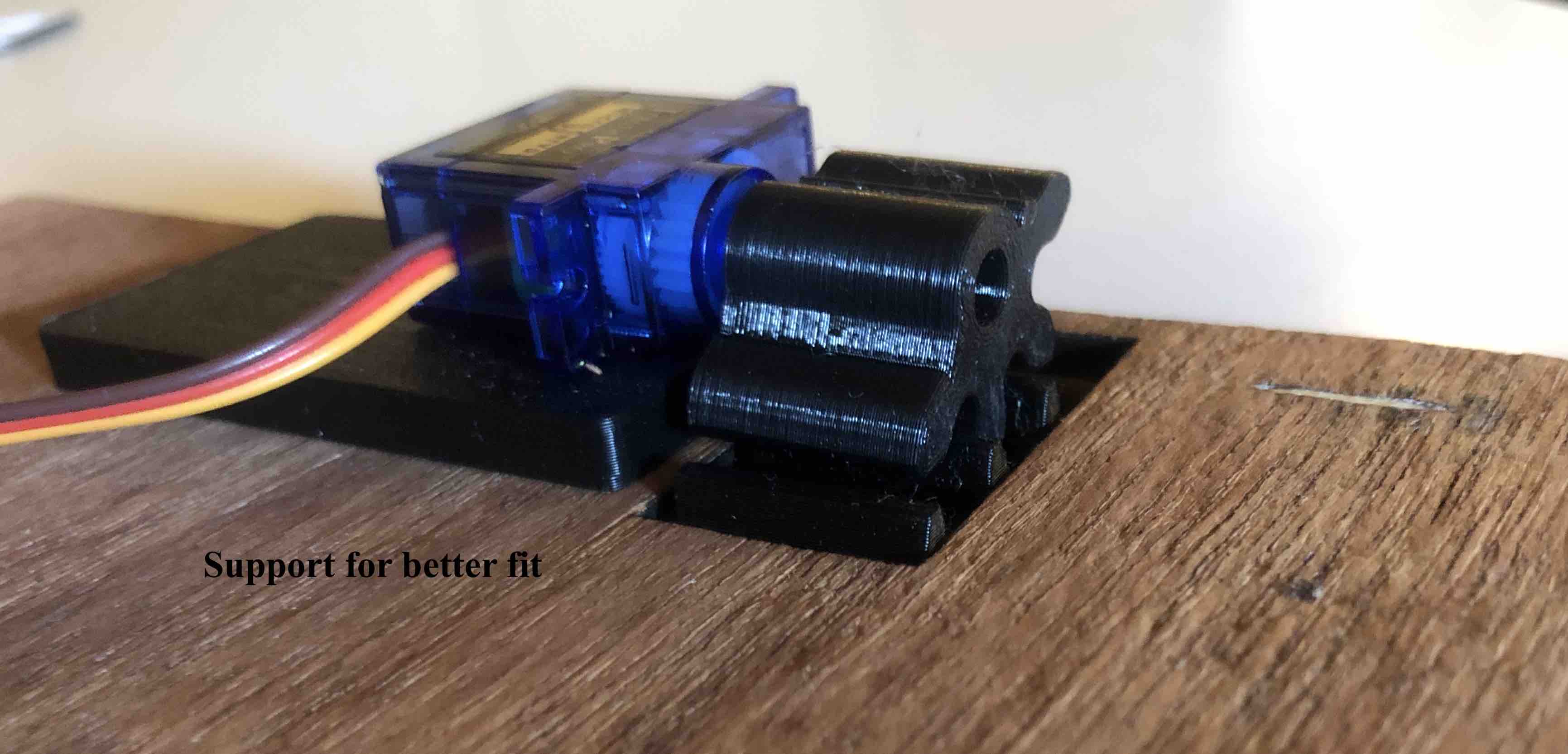
HOw it works:
Electronic Programming
During the embedded programming week I was able to get the kaypad to control the servo motor. This is pretty close to what I want my final project to look like. I do want to add an LCD screen and maybe change out the keypad for a fingerprint sensor.
I wanted to add a LCD screen to the assembly above but I was unable to find some good tutorials on how to do that. I did find one with the LCD screen and keypad. I attempted it during the input devices week. Here is the result:
Fingerprint sensor
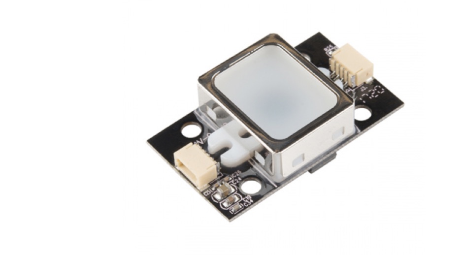
To get a head start with the electronics, I decided to go ahead and order a fingerprint sensor. Abhishek Bali, the co-ordinator for Fabacademy at Dassault Systemes, was kind enough to get one shipped to me. The sensor that I decided to go with is the GT-521FX2 Fingerprint Scanner from Digi-Key. I decided to go with this one since it is small and compact, while highly efficient.
The Datasheet is linked here.
The Programming Guide is linked here
The hookup guide is linked here.
I sat down ready to play around with my new toy when I realized that I needed some balance plug extension leads. Abhishek ordered some for me once again and they should be here next week.
This is a tutorial that I want to attempt soon.
6/10/2020
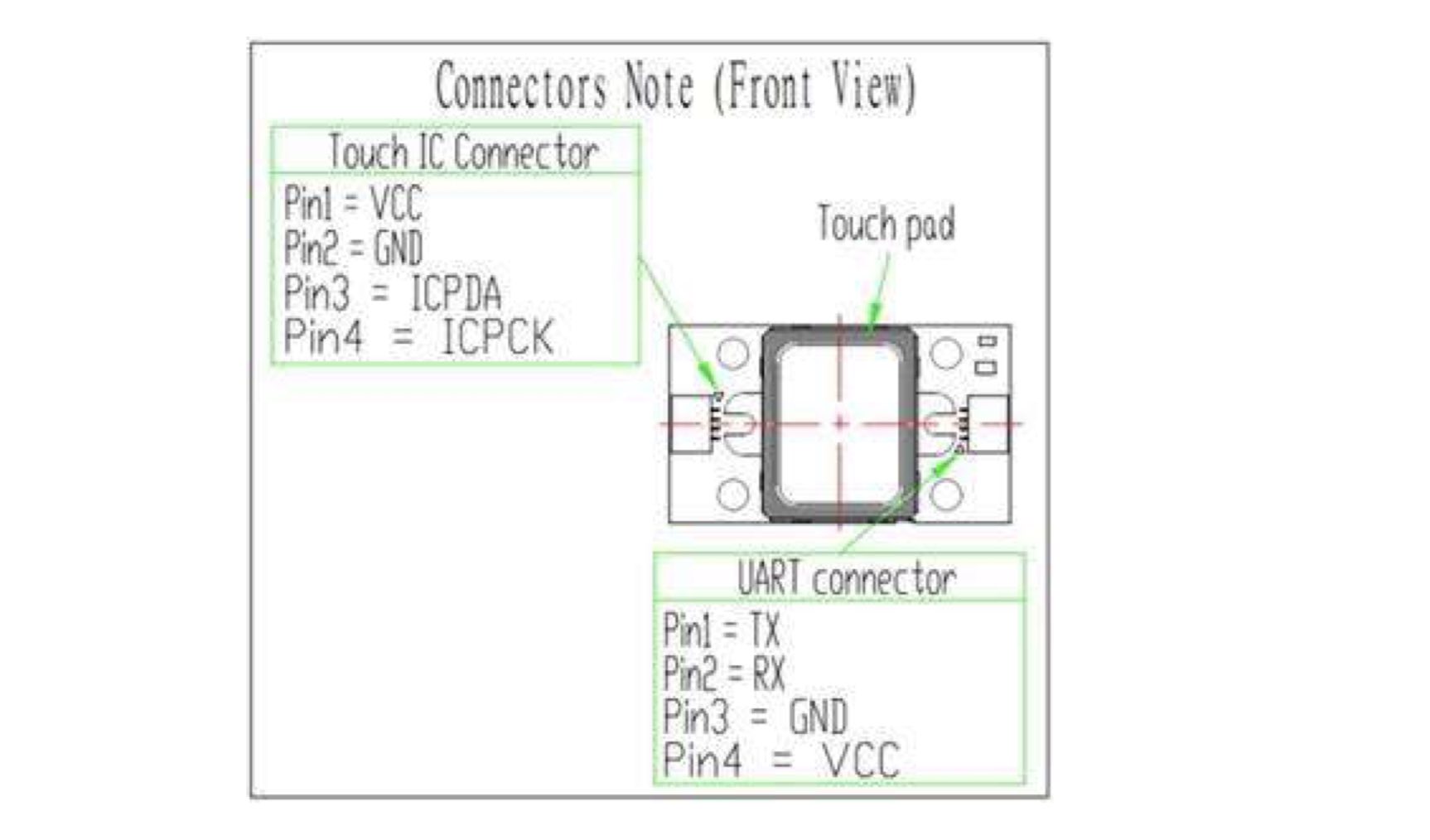
I ordered some Qwiic cables online and they arrived this week so I was able to start experimenting with the sensor. I scoured the internet for a good video tutorial with the sensor but couldn’t find any. Projects done for Fabacademy used the earlier version of the sensor so it was hard to follow along. I finally realized that the product page had a hookup guide. I followed along closely. This is the a useful guide on how the pins connect:
With polarity labelled:
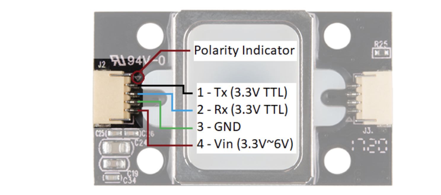
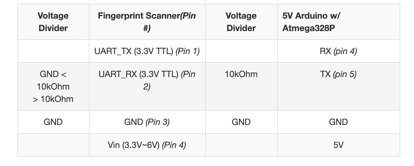
There is a marking next to the JST-SH connector that indicates polarity. The JST-SH connector breaks out the pins for serial UART and power. While the input voltage is between 3.3V and 6V, the UART’s logic level is only 3.3V. You will need a logic level converter or voltage divider to safely communicate with a 5V device.
Hardware Hookup
The hookup guide has a few options on how to hookup the sensor. I went with the second option: connecting with a 5V Arduino. Here are the things required:
- Fingerprint Scanner
- Qwiic cable
- Breadboard
- Arduino uno
- Bi-Directional Logic Level Converter or 3x 10kOhm Resistors
- Jumper wires
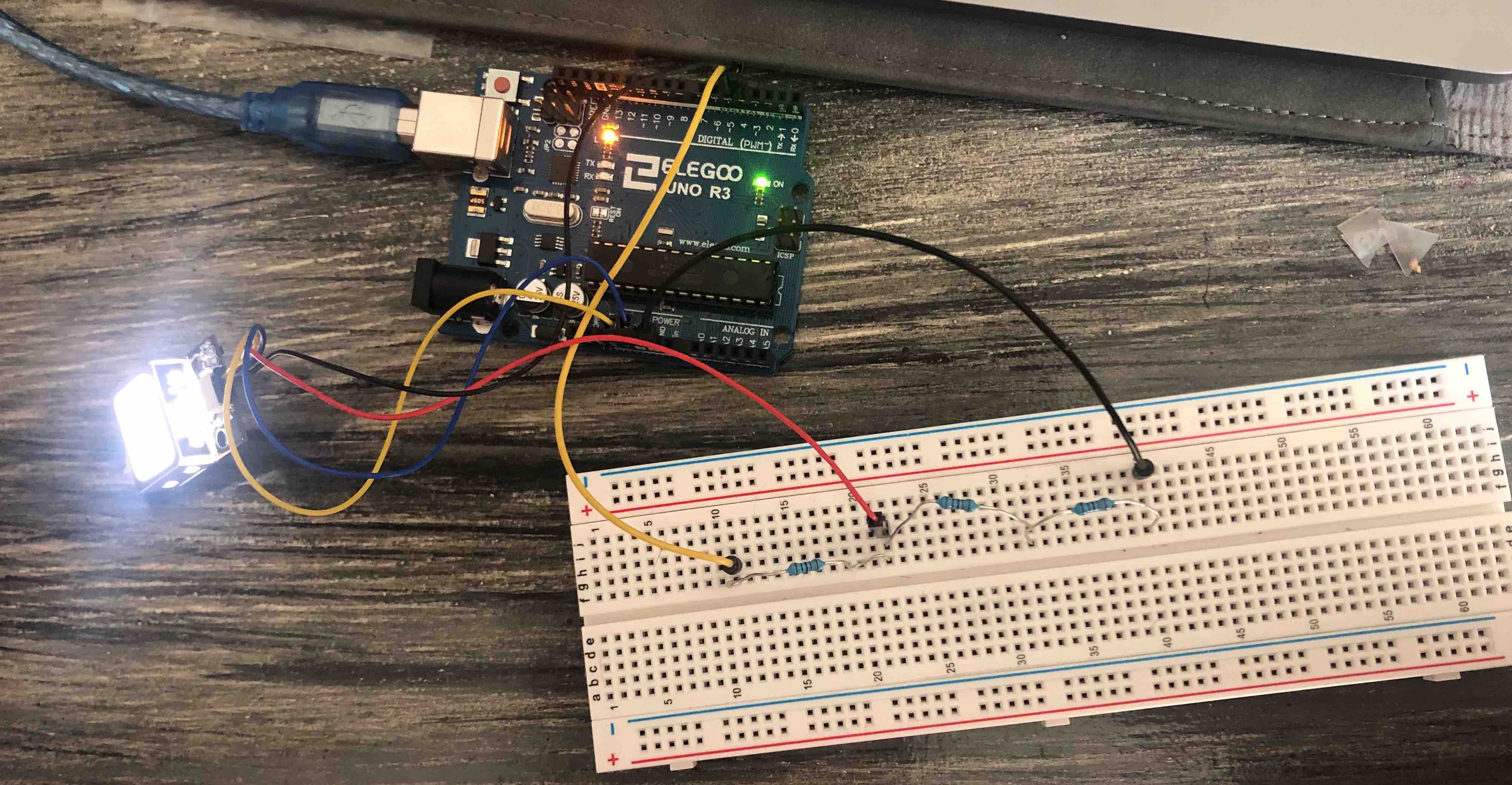
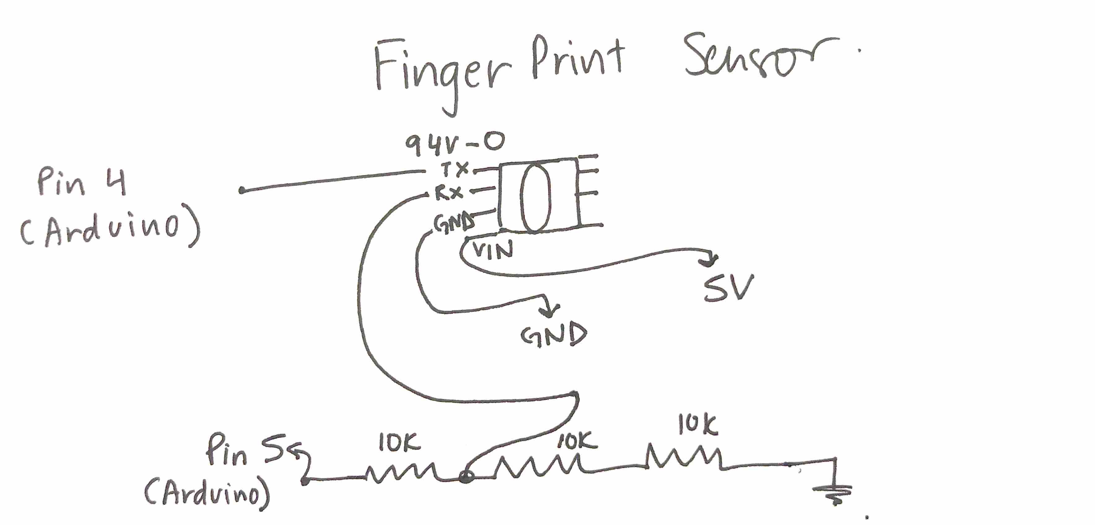
Since I don’t have a Bi-Directional Logic Level Converter, I decided to use 3x 10kOhm resistors to divide the voltage from a 5V Arduino down to 3.3V for the fingerprint scanner. This is the how I connected the wires:
This is what it looks like:
Coding
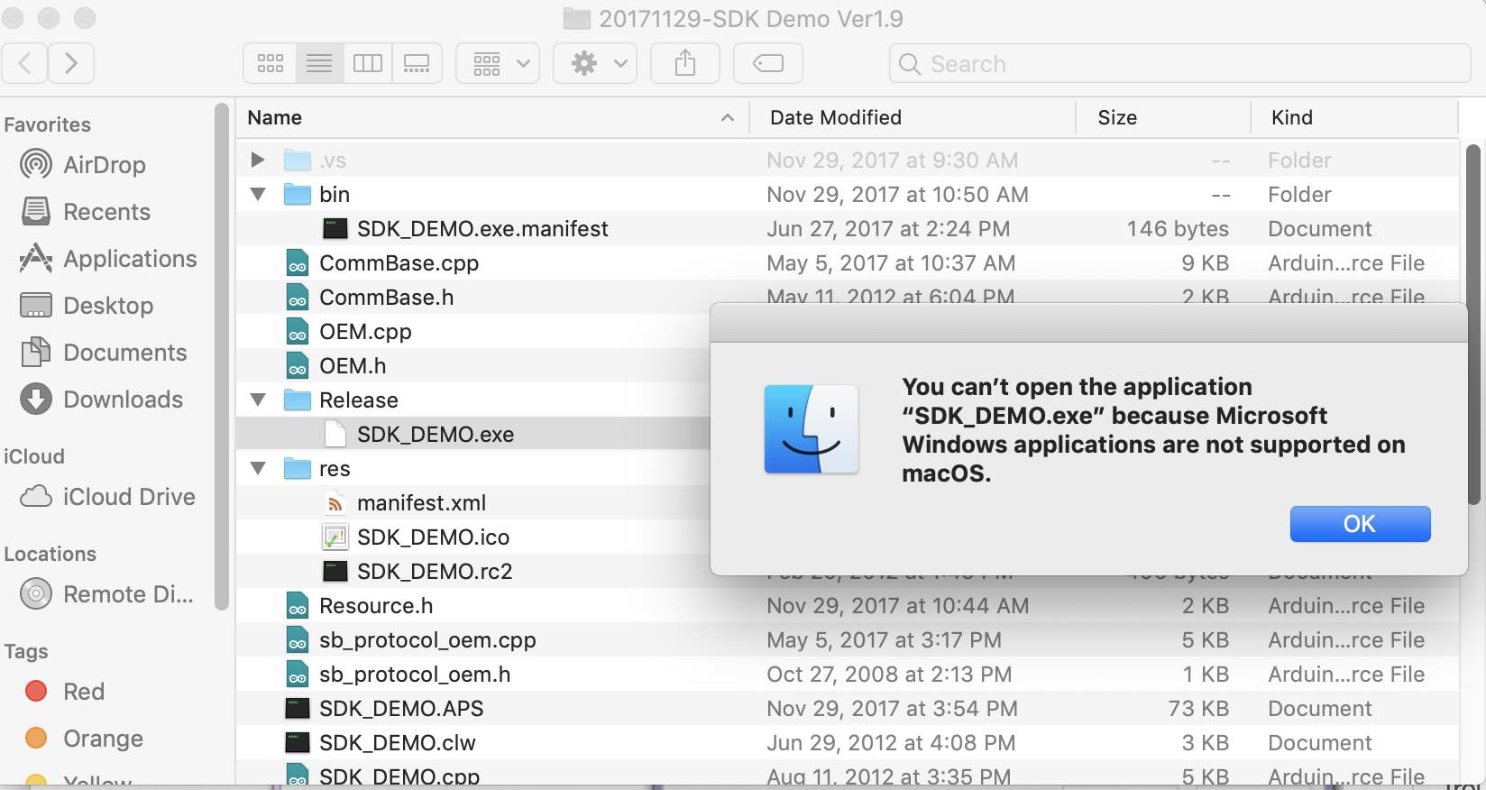
The next step in the hookup guide was to download the SDK software. The link to download is availible on the product page. I downloaded it and followed the instructions on the guide but was unable to open the app. This is probably because I am using a Mac.
I looked online on how to use the SDK software on a mac but didn’t find anything helpful. I thought I was going to be stuck here for a long time. However, I scrolled through that section on the guide and there is actually a way to replicate what the demo software does in Arduino code. Luckily there is a fingerprint scanner Arduino library written by jhawley. The code does most of the leg work for you and handles a lot of the complicated protocol commands. You can download it on the GitHub repo.
The library has three examples. Each one performs a different task with the fingerprint scanner:
- Blink the white LED.
- Enroll a fingerprint.
- Attempt to identify the fingerprint against the local database.
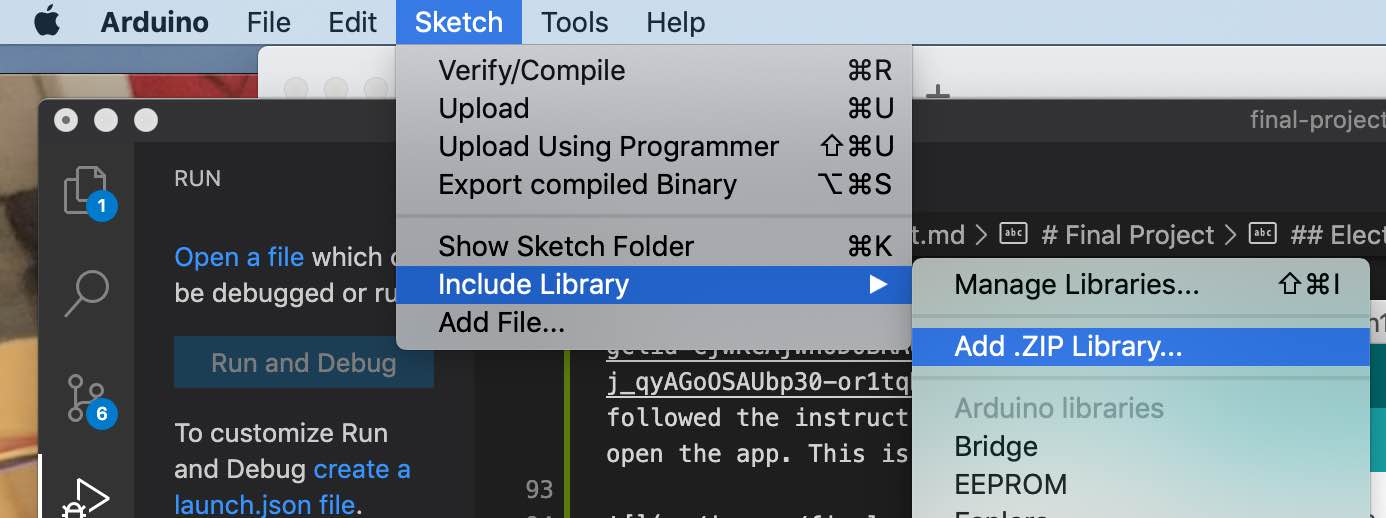
I tried the first example to make sure everything is hooked up properly. I ran the blink code from the library but it didn’t work because the FPS_GT511C3.h library was not added. I added this by going to include library and then selecting the zip folder downloaded from Gitlab.
After this was done, the rest of the process was pretty straightforward. This is the output from the blink function:
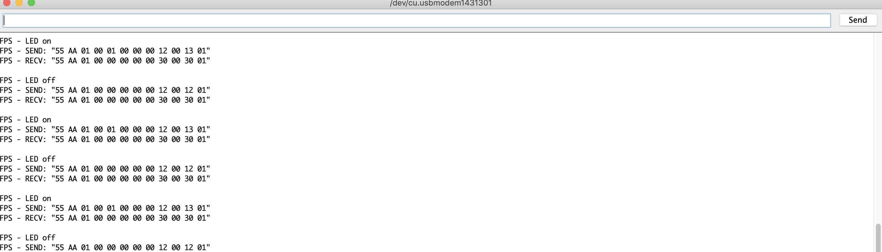
Fingerprint scanner blinking:


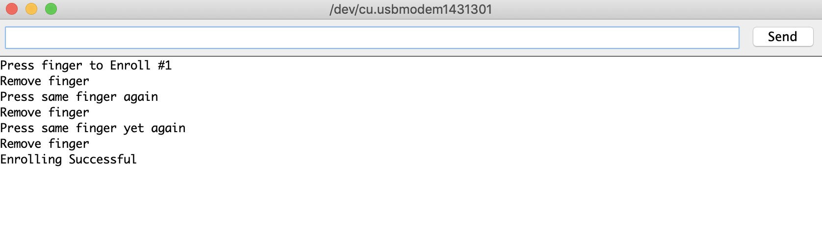
I ran the next example code, which was to enroll a fingerprint. Here is the result on the serial monitor:
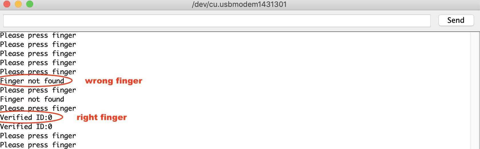
Finally, I checked the verification code. Here is the output on the serial monitor:
OLED
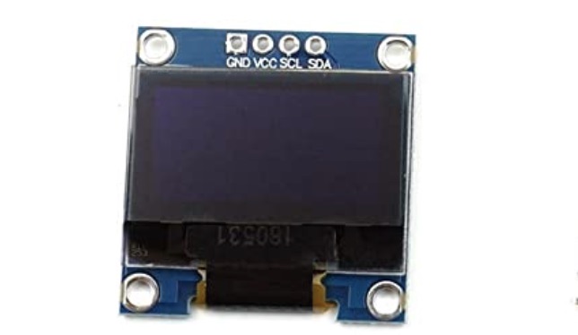
Initially, I thought I was going to use a LCD screen for the display. However, during one of the lectures, Neil introduced OLEDs and it just seemed like a less-bulky, better looking, sleeker option. Therefore, I asked Abhishek to order one. This is the one that I ordered from Amazon:
I looked online for some tutorials and found this one very helpful.
What are OLEDS?
OLED is an abbreviation for “Organic Light Emitting Diode.”The “organic” in OLED refers to the organic molecules used in creating these devices. Organic molecules are simply molecules that are based around lines or rings of carbon atoms. As with a standard LED, an OLED emits light photons of a specific frequency when an electrical current is passed through it.
Some advantages of OLEDs include being lighter, thinner, flexible, brighter, and more versatile than LEDs and LCDs. However, they are usually more expensive and and can be damaged by water.
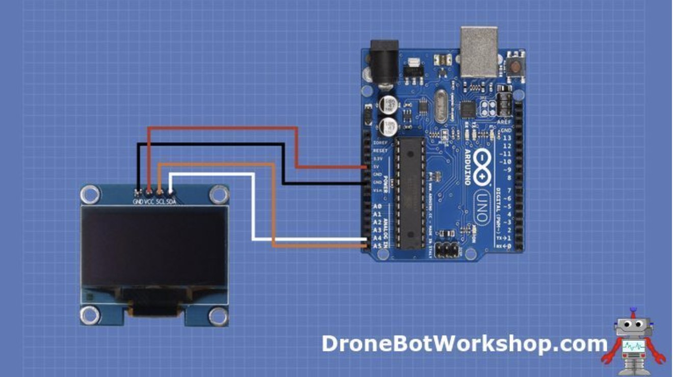
Electrical Connections
The OLED has 4 connection pins: - GND: connected to ground on the arduino. - VCC: the power supply connected to 5V on arduino. - SCL: The I2C clock. Connected to A5. - SDK: The I2C data line. Connected to A4.
Coding
To start off, I had to install two arduino libraries: - Adafruit SSD1306 - Adafruit GFX
The SSD1306 library had some example codes that I could run. This is accessed by going to Files -> examples -> adafruit SSD1306 and then selecting the right type of OLED> I selected the 128X32 I2C. I ran it and it worked.
This is where I stopped in 2020.
2022
In 2022, I checked that the components were still working. Then I combined the fingerprint sensor code with the servo motor code. This was the most time consuming part. Next, I designed a board with Attiny1614 as the microcontroller on kiCAD and then uploaded it. In the process, I lost 2 fingerprint sensors, and made 3 different boards. But it finally worked! Here is the process.
Checking components
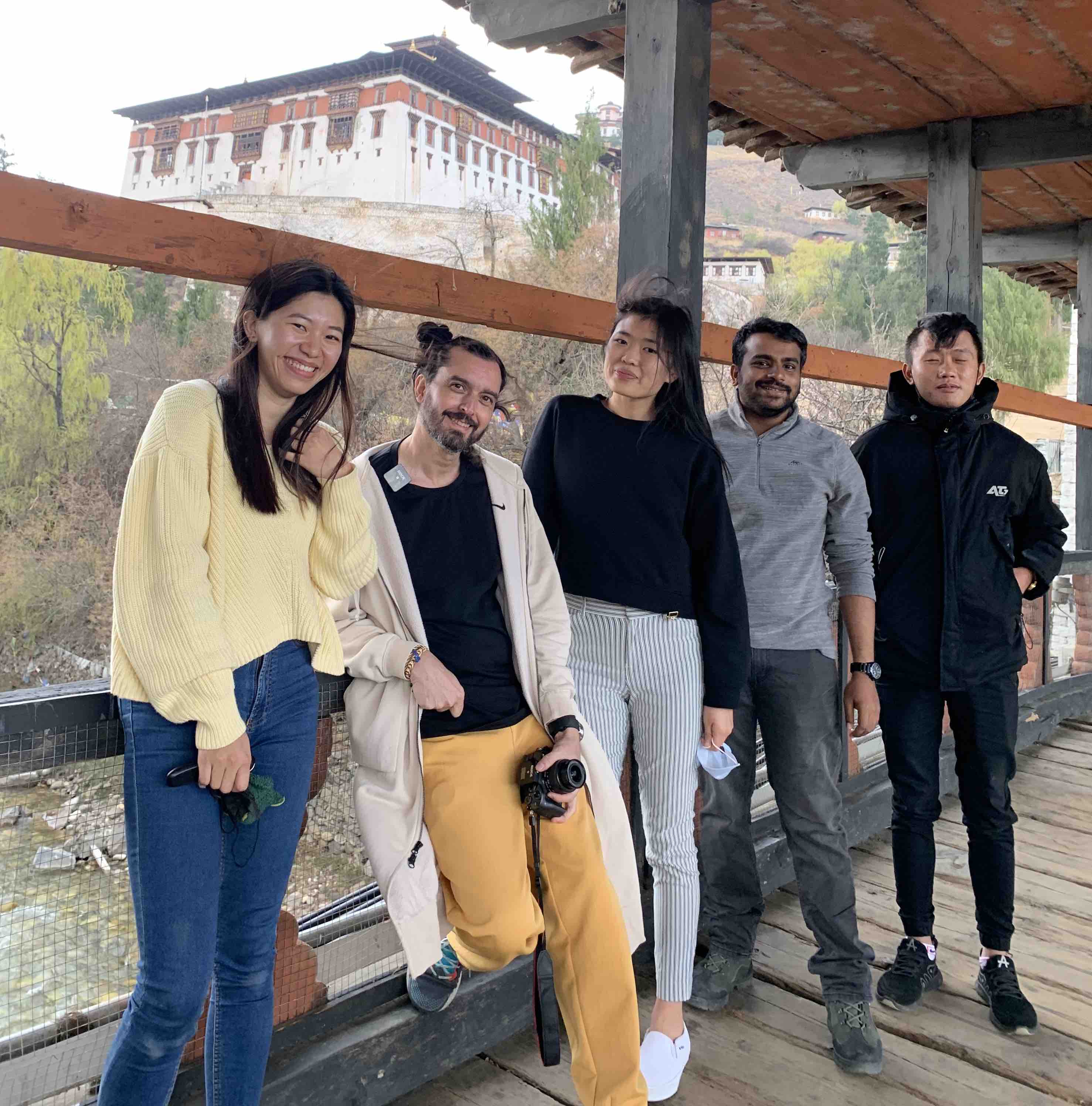
I picked up where I left off the project in 2020. I brought the fingerprint sensor with me to Bhutan along with the rest of the arduino kit. I also had the help of Fran and Sibu while working with them to set up the Fab Labs and Super Fab Lab in Bhutan.
The first thing I did is to make sure that the fingerprint sensor is working since it is quite fragile. I refered back to the documentation and ran the sample code.
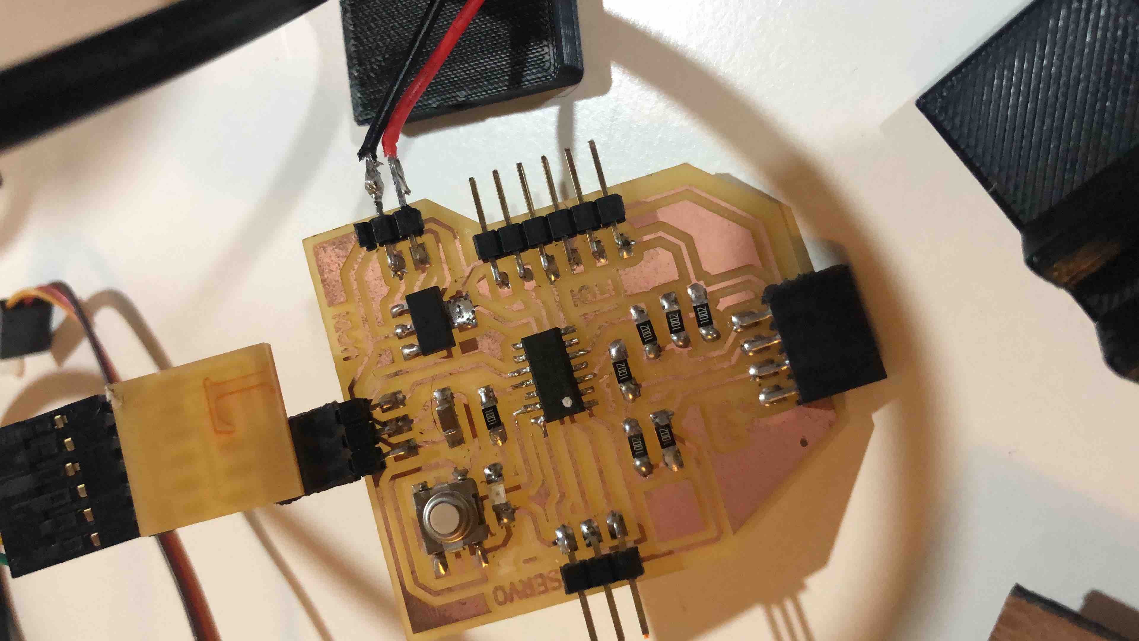
This is how the fingerprint sensor is connected:
It worked!
I then tried the servo motor code and that worked as well. Now the real challenge was integrating the code. Fran helped me with this.
I wanted to integrate 3 components:
- Fingerprint sensor
- Servo Motor
- OLED
However, the OLED library was taking up too much memory so I decided to combine the Finger Print Sensor and servo motor first.
Fran first said that I needed to make a diagram for my code and how i wanted it to flow. This is the chart that I drew:
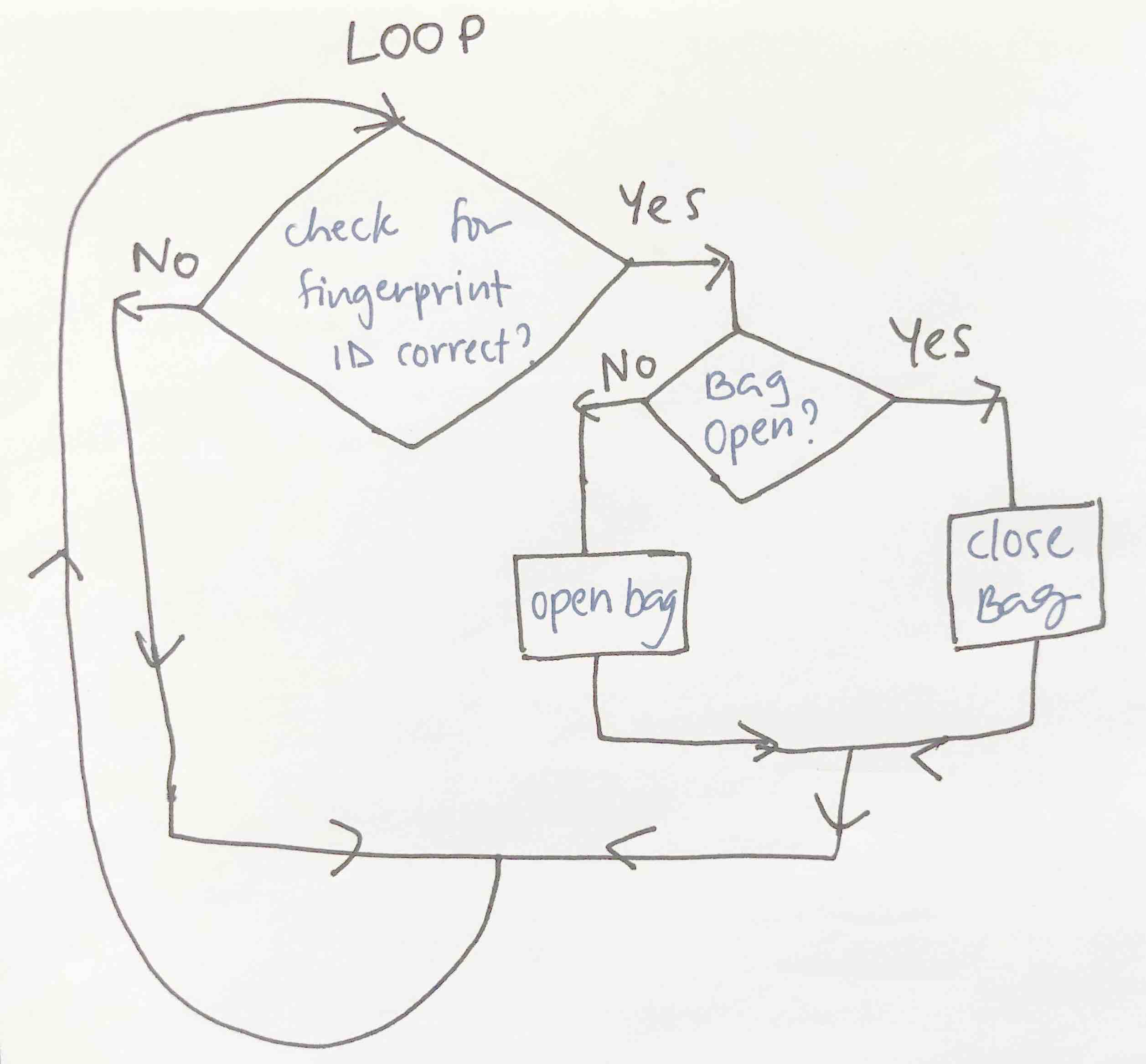
I combined the servo code and the FPS (Fingerprint sensor) code and the servo code by first opening up the FPS code (the longer more complicated one) and then adding the servo code in between one by one.
I complied the code for the servo and the FPS and finally got it to do this:
The servo jitters in between when its in idle state and I’m not sure how to fix that problem. Fran suggested that I look into connecting the other side of the FPS since that is where the “Interrupt” is connected. It stops the main program and runs another program. When it detects a finger is placed on the FPS and then executes the main program. This saves battery and I think this would stop the jittering as well. This is on my list of “To-do.”
Electronics Production
Designing my board
Suhas suggested that I work with the Attiny1614 as my micro controller. I designed my board on Kicad and milled it. This is version 1 of my final project board:
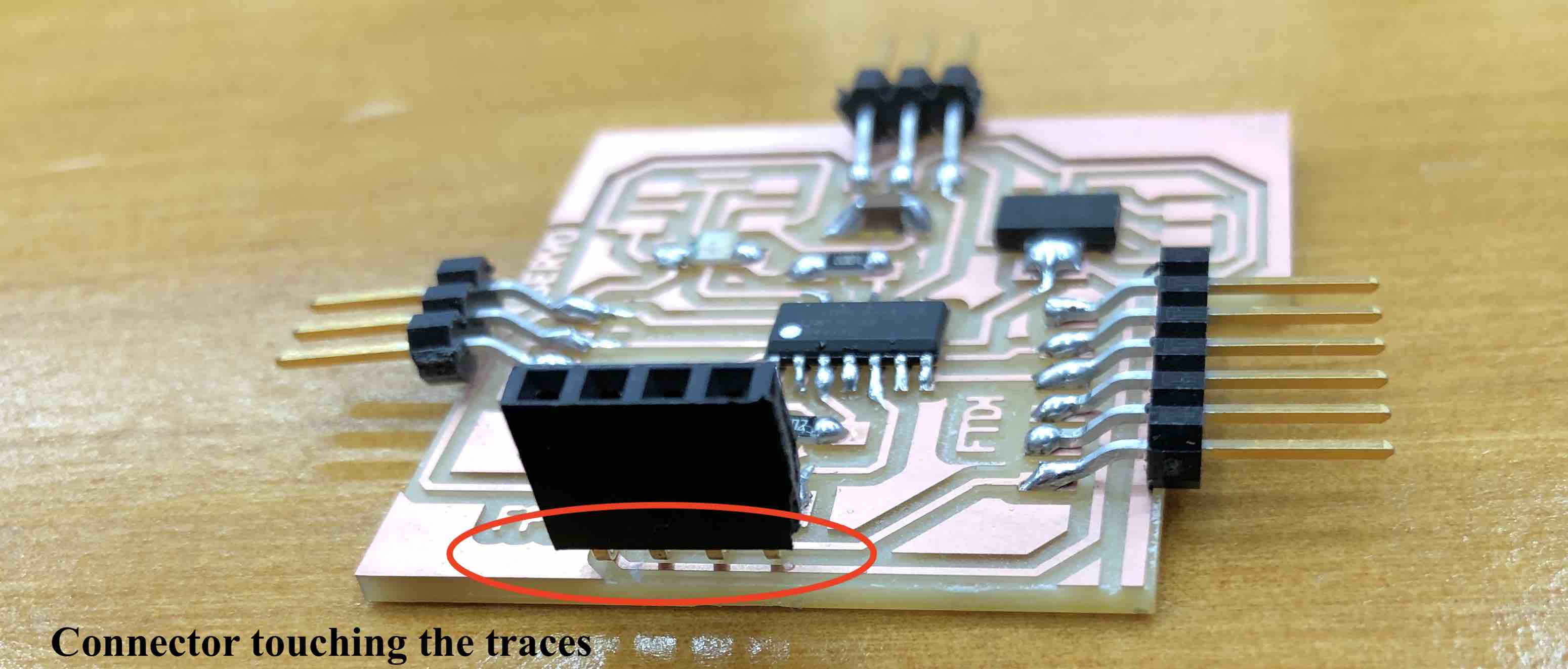
I did not notice before I connected everything but as you can see in the picture above, the connector for the fingerprint sensor is touching the traces which shorts the connection. I connected my fingerprint sensor to this and it didn’t work. I was wondering why and I suddenly noticed that the sensor was heating up. I immediately knew that it was shorted. I was hoping that the board was fried and not the sensor. I connected the fingerprint sensor to the arduino and it started heating up. 1 Finger print sensor down.
I milled and soldered another board and I prayed to god that this time around it would work. I managed to get a similar Finger print sensor from Amazon india fron the Bhutanese black market amist the lockdown. I asked Suhas to check my board design once again and he said that it should work if the connectors were not shorted.
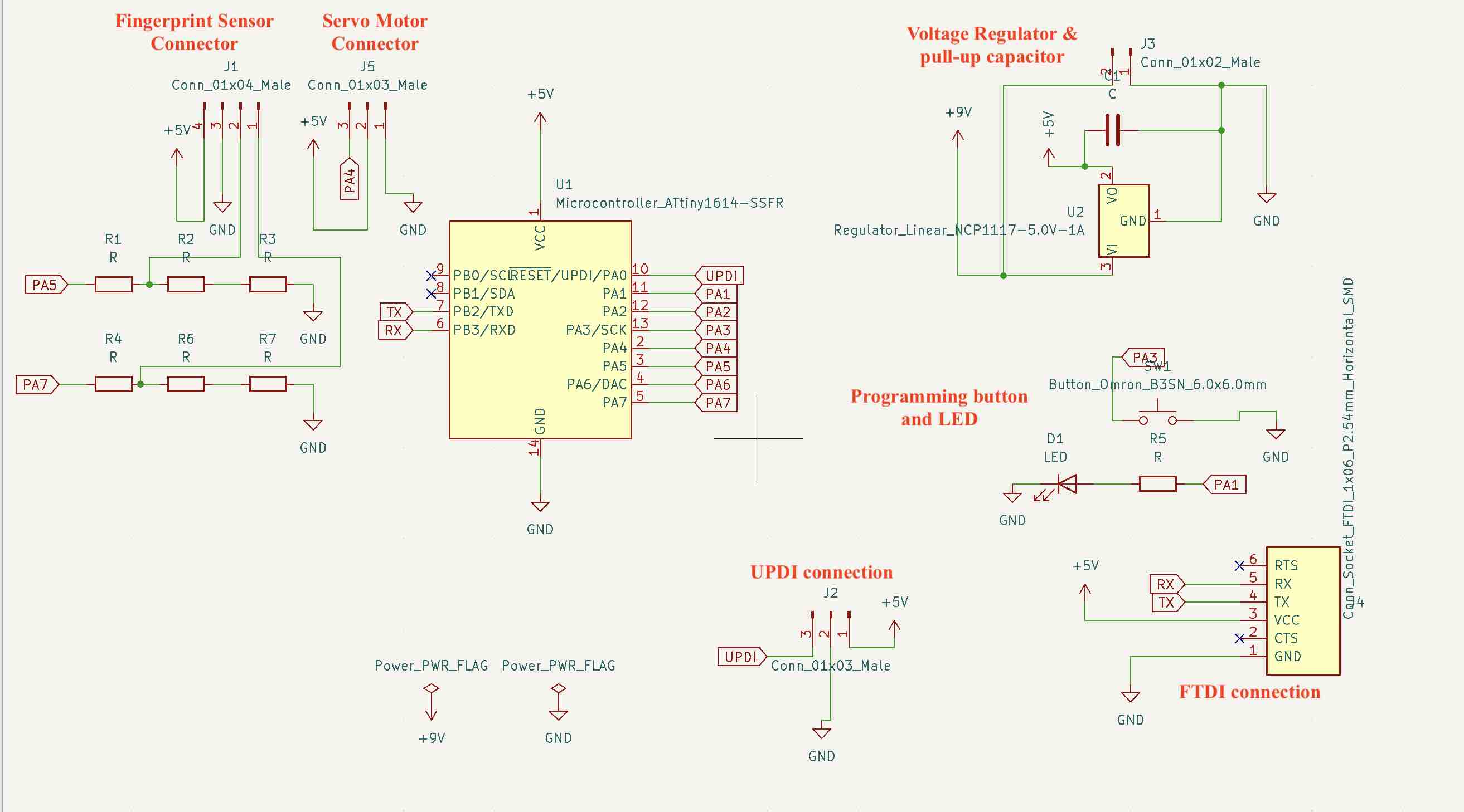
This is the schematic for design 1:
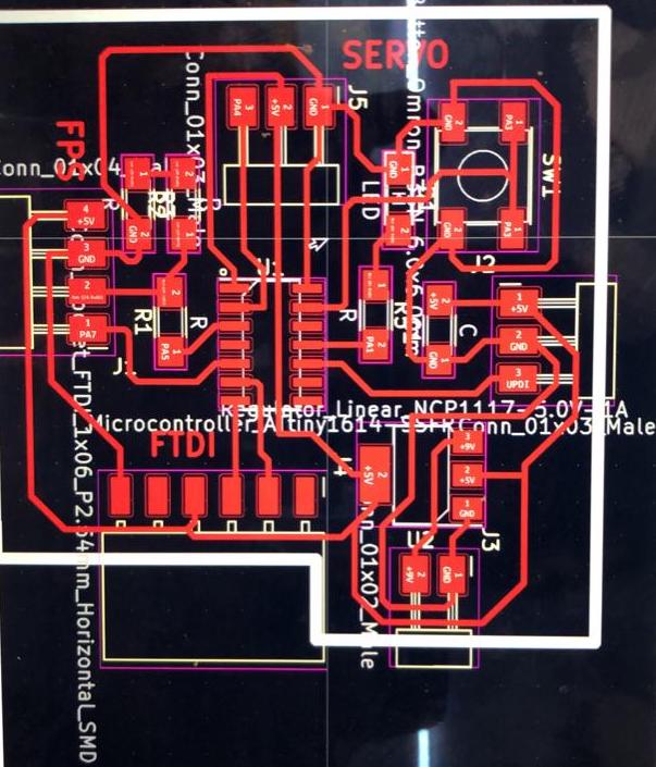
PCB deisgn:
To first check if the board is working I uploaded a simple LED blink command. This is the settings on arduino.
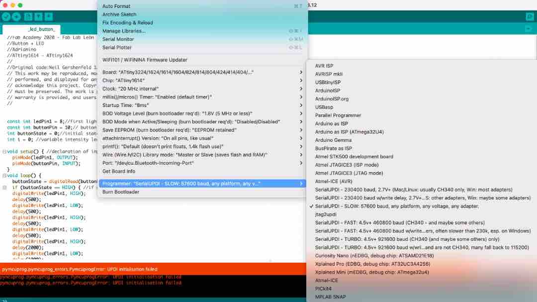
At first I tried to program it directly through the FTDI cable. It didn’t work and I got this error:
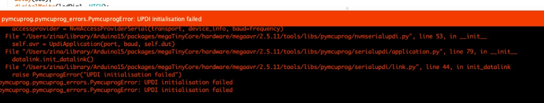
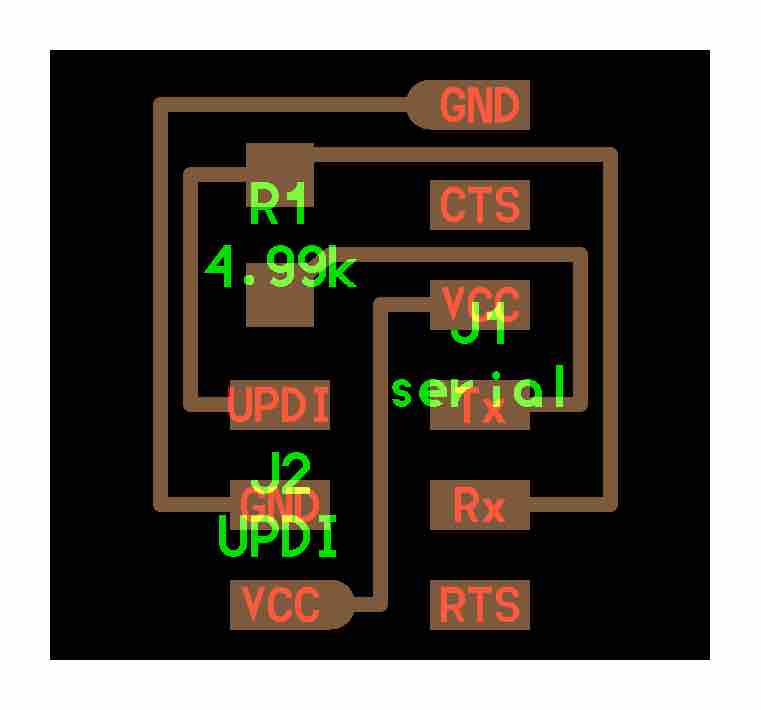
I asked Suhas sir and he said that it needs to be programmed through the UPDI port and I need to mill a UPDI programmer board availible in the embedded programming week. This is the link.
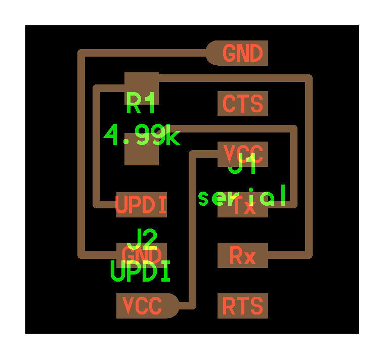
The board:
With a FTDI connector, I connected it to the UPDI programmer board and that to my board.
I uploaded the program and it worked! and I was happy for a whole 10 minutes. I managed to make this video while it was working:
However, while connecting the Finger print sensor once again, I accidentally switched the RX and TX pins. This means that 5V was provided to the TX pin and it was burnt.
As you can see in the table above, it specifies that RX and TX pins are 3.3V. However, it suggests a volatage divider through 3 10K resisitors only for the TX pin. I followed this while testing on arduino and it worked so I thought it was OK. Anyway, 2nd fingerprint sensor down. :(
I ordered one more fingerprint sensor and really hoped that this one will not get damaged. I added a voltage divider for the RX pin as well.
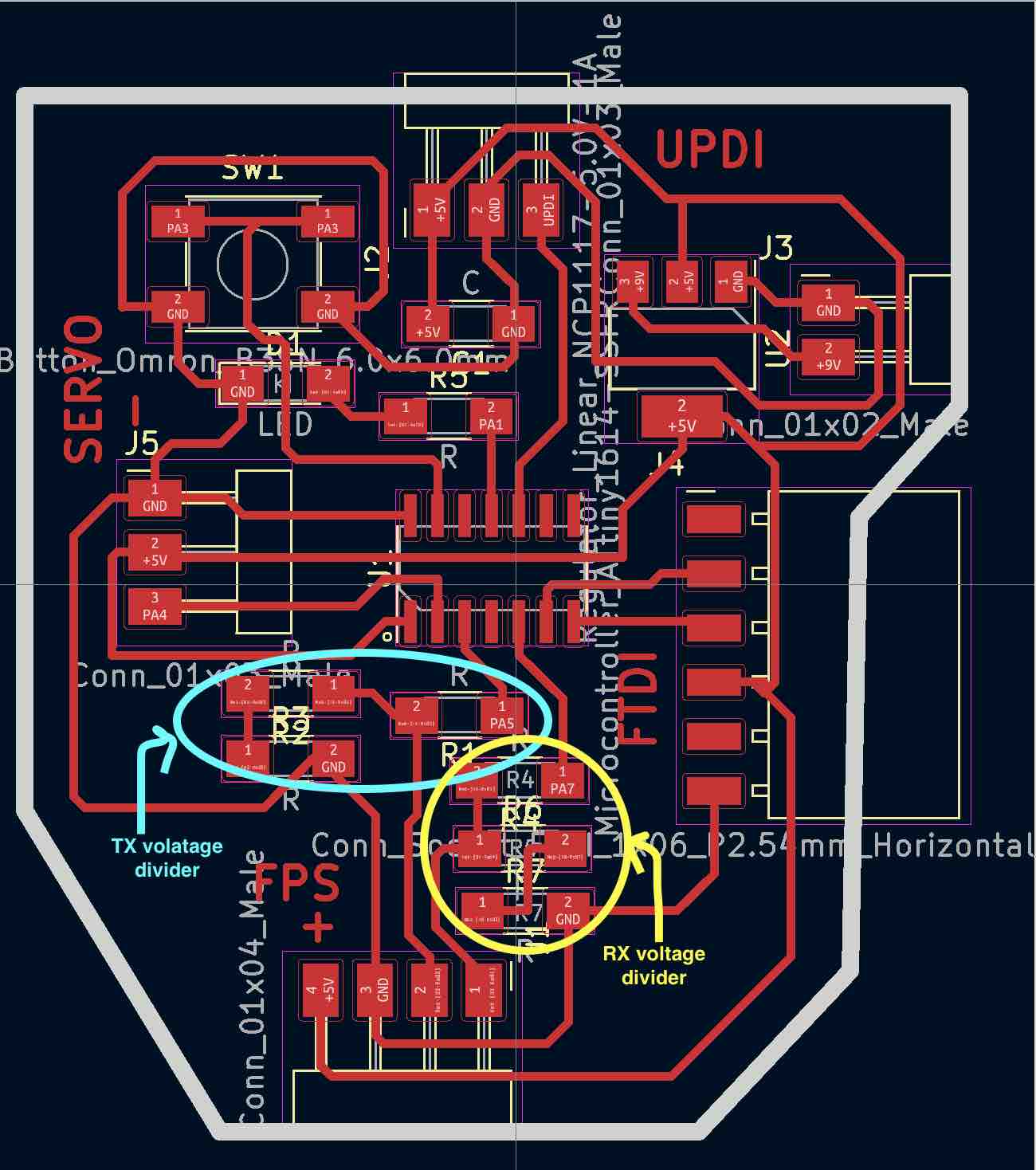
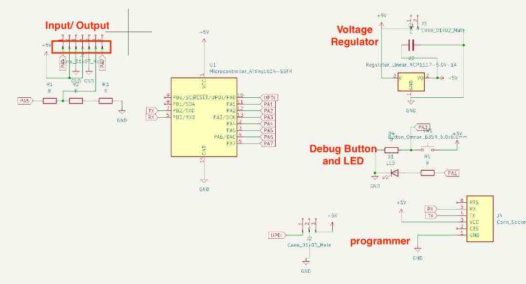
This is the updated schematic:
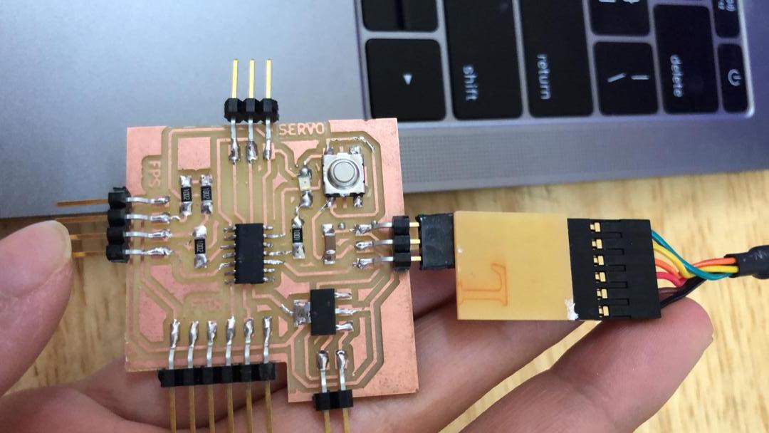
This is the second board soldered and milled:
I uploaded the program through the UPDI programmer and it worked!
Assembly
I first assembled the bag and stuck it with super glue to give it extra reinforcement. Then I integrated the electronics. I found a scrap piece of wood that fit perfectly to fit the electronics underneath.
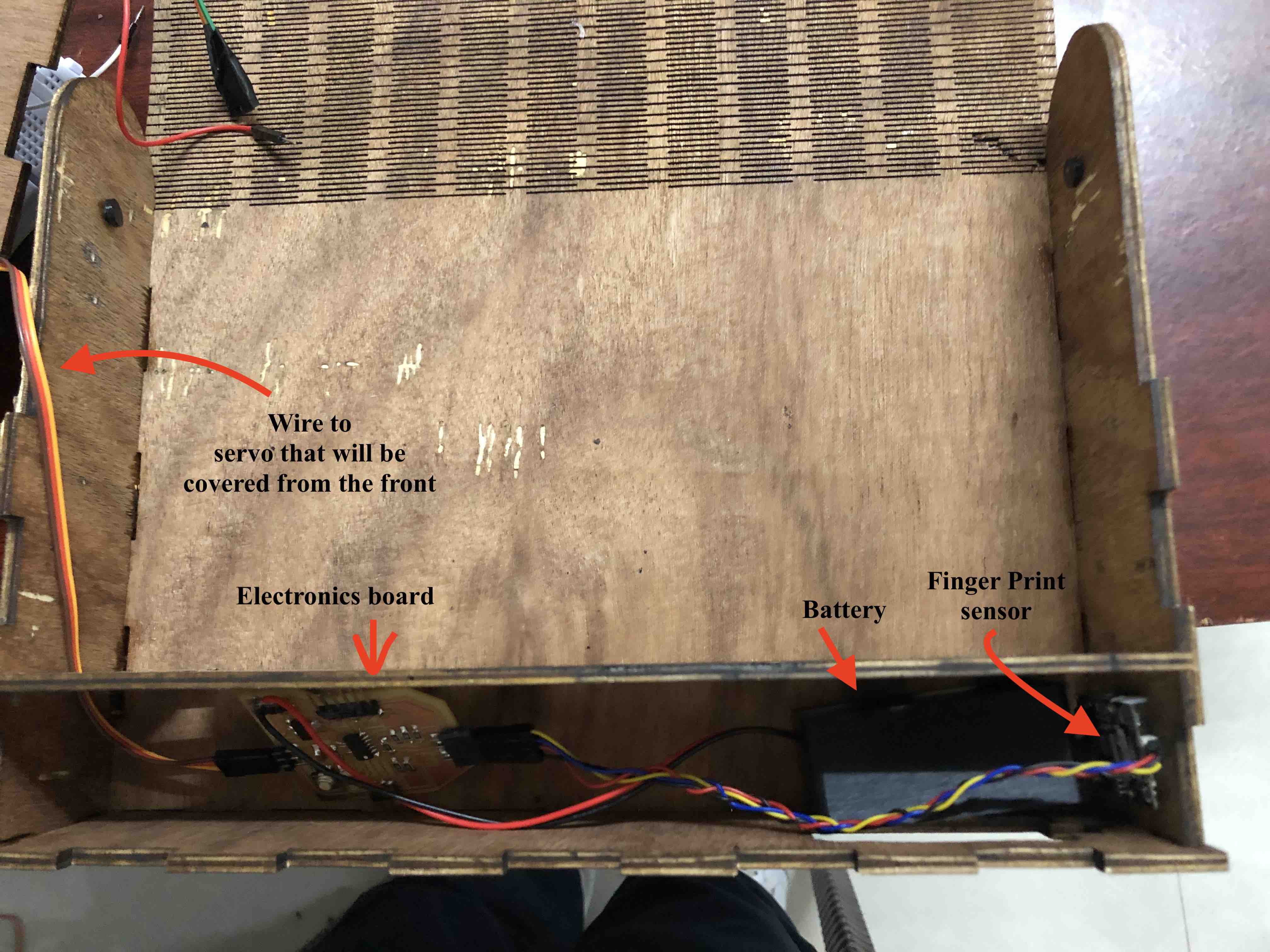
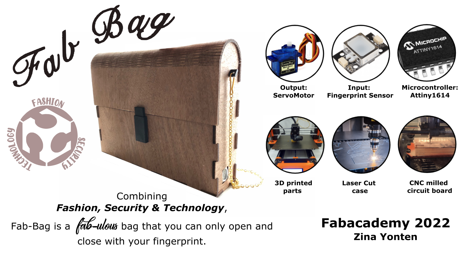
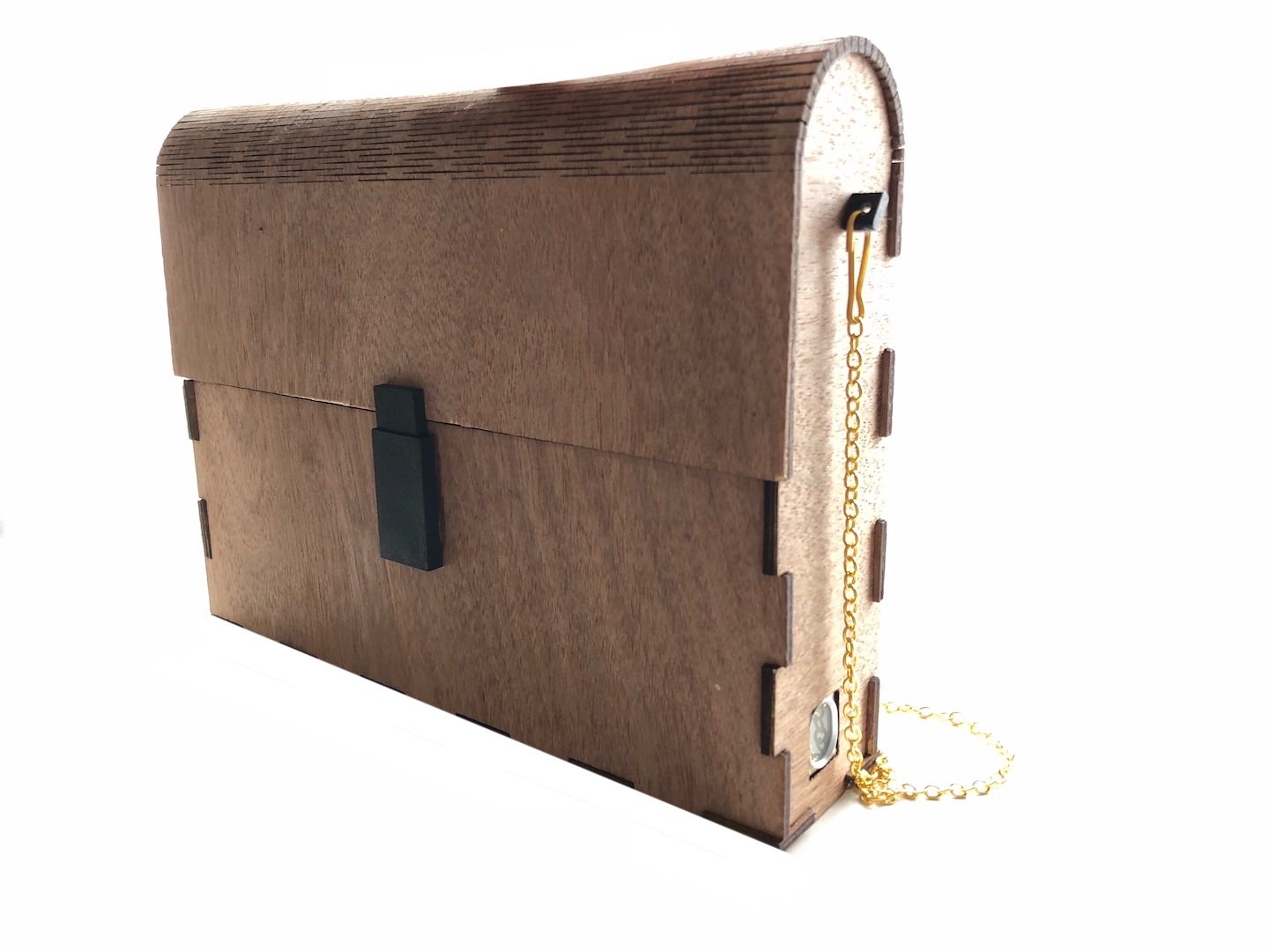
With everything assembled, this is the final product:
Q and A
What will it do?
A locking mechanism for bags that will open with a keypad or fingerprint sensor. Additionally, I hope to add a bluetooth chip to connect to an app to set the passcode. Another spiral is to add a GPS unit to track the bag.
Who’s done what beforehand?
There have been a couple of locking mechanisms done before for final projects. I listed a few below.
- Aaditi Kharade from the Fabacademy class of 2019 did a key security system that uses similar components that I have in mind.
- Andres Alnor from the graduate class of Fabacademy 2018, did a Facial Recognition Safe Box that unlocks a box through facial detection.
- Jasim Bourseli did a smart jewelery box that opens via an app.
- This cool fingersensor lock at Walmart.
What will you design?
- Design a laser cut bag as the outside shell on Fusion360
- Design a 3D printed box for the electronics on Fusion360
- Design 3D printed strap for the bag on Fusion360
- Design a PCB for the electronics on EAGLE
What materials and components will be used?
- Wood for the laser-cutting the shell
- Filament for 3D printing
- Materials for cutting out my PCB
- Keypad/ Fingerprint sensor
- Servo motor with the latch attached
- Bluetooth module ?
Where will it come from?
Most of the parts are available in the Fablab inventory. The fingerprint sensor and the servo motor will be ordered from Digikey.
How much will they cost?
The fingerprint sensor is around $45-$60. The servo motor is around $10.
What parts and systems will be made?
I plan on buying the electronic components like the fingerprint sensor, servo motor and the microcontroller. Everything else will be made in the lab.
What processes will be used?
Laser-cutting 3D-printing PCB production
What questions need to be answered?
- Use the keypad or the fingerprint sensor?
- Need to figure out the code
- How to power it?
- How will the electronics be placed inside the bag?
- PCB still needs to be designed on EAGLE
How will it be evaluated?
My project should be successful if it can incorporate 2D and 3D design, additive and subtractive fabrication processes, electronics design and production, embedded microcontroller interfacing and programming, system integration and packaging. The design and production of the bag should cover the 2D and 3D design aspect. 3D printing of the strap and the casing for the electronics should cover the additive fabrication process. Design and production of the PCB will cover the electronics. In this project, the input will be the passcode and the output will the motor turning to unlock the bag.
Bill of Materials
| Part | Provider | Quantity | Price | Total |
|---|---|---|---|---|
| Plywood Sheet 600x300x3mm | Fab Lab Mandela | 1 | $ 10 | $10 |
| PLA Filament (grams) | Fab Lab Mandela | 200 | $ 0.1 | $ 20 |
| Gold chain straps | Amazon | 1 | $ 2 | $ 2 |
| Finger print sensor | Amazon | 1 | $ 27 | $ 27 |
| Servo Motor | Fab Lab Mandela | 1 | $ 2 | $ 2 |
| 9V battery holder | Fab Lab Mandela | 1 | $ 1 | $ 1 |
| 9V rechargeable battery | Amazon | 1 | $ 7 | $ 7 |
| PCB - Copper Board | Fab Lab Mandela | 1 | $ 0.2 | $ 0.2 |
| PCB - Attiny1614 SMD | Fab Lab Mandela | 1 | $ 1 | $ 1 |
| PCB - R10k SMD | Fab Lab Mandela | 6 | $ 0.05 | $ 0.3 |
| PCB - R1k SMD | Fab Lab Mandela | 1 | $ 0.05 | $ 0.05 |
| PCB - C0.1uF SMD | Fab Lab Mandela | 1 | $ 0.3 | $ 0.3 |
| PCB - Led SMD | Fab Lab Mandela | 1 | $ 0.2 | $ 0.2 |
| PCB - Connector strips SMD | Fab Lab Mandela | 1 | $ 1 | $ 1 |
| Total | $ 72.05 |
License
This project is licensed under Creative Commons Attribution-NonCommercial-ShareAlike 4.0 International License.
This means you are free to:
- Share — copy and redistribute the material in any medium or format;
- Adapt — remix, transform, and build upon the material.
Under the following terms:
- Attribution — You must give appropriate credit, provide a link to the license, and indicate if changes were made. You may do so in any reasonable manner, but not in any way that suggests the licensor endorses you or your use;
- NonCommercial — You may not use the material for commercial purposes; ShareAlike — If you remix, transform, or build upon the material, you must distribute your contributions under the same license as the original.