7. Computer controlled machining
This was by far the craziest week of the course owing to COVID-19. Between shutdowns, social distancing, travel bans, my sister’s visit over her spring break, and no rice at the grocery store, I managed to design a mini storage drawer for my vanity desk at home. I wanted to design something small since I don’t have a car here and wanted to be able to carry it home. I used Fusion360 to design it and Vcarve to set the toolpath before sending it over to Shopbot to cut.
Group Assignment
The CNC Router that we have at the Dassault Systemes Fablab is the 3-axis Shopbot.

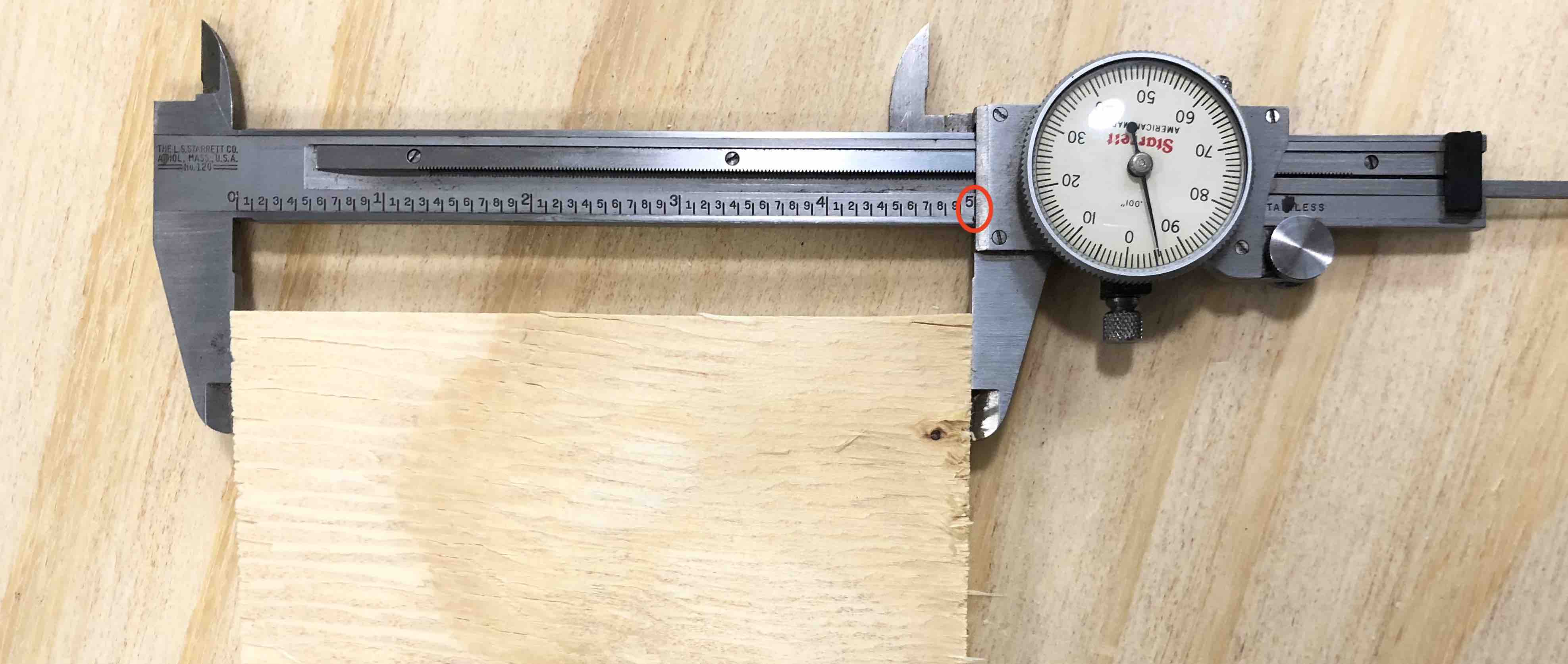
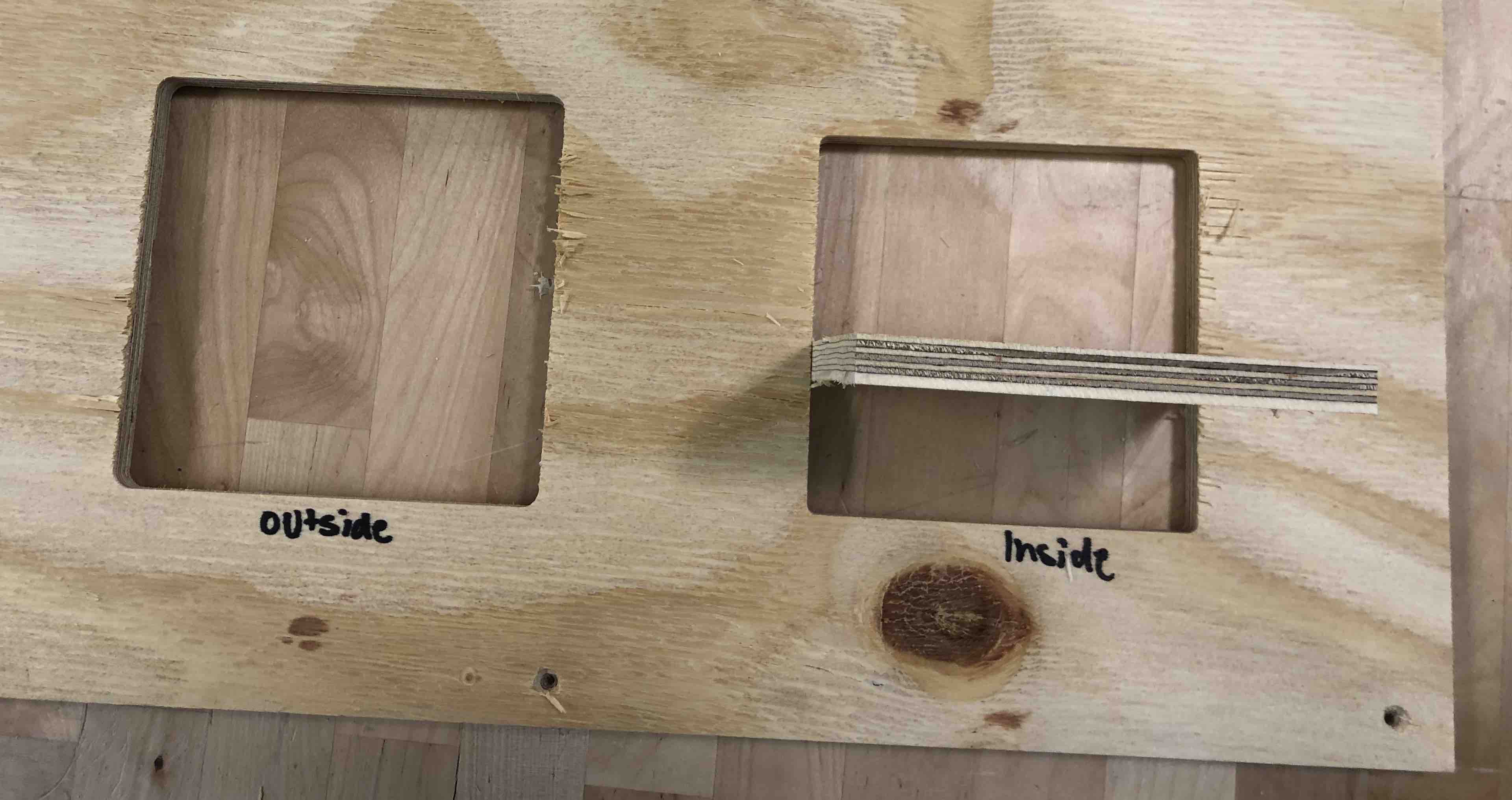
For the group assignment we had to test the runout, alignment, speeds, feeds, and toolpaths for our machine. First, we decided to mill out two 5” by 5” squares. We cut one square with the inside toolpath and the other with the outside toolpath. We did this so that we could compare the accuracy of the two toolpaths and also see if the cut out square would fit in the square hole.

As you can see from the picture above, the outside toolpath cuts the stock from the outside of the sketch. This is what is usually chosen for cutting things out. The inside toolpath cuts the part from the inside. This is used for milling holes and pockets. There is another toolpath that mills on the line. We did not test this out. However, this is usually used for engraving. We measured the sides of the square cut out from the outside cut and it was pretty accurate.
Before you cut, you also have to be sure to add tabs in. This will leave a little bit of the cut part joining it to the main stock. This is to prevent the cut part from jumping up and possibly ruining the machine or injuring someone.

Next, we tested if it would press fit. It did after some hammering and chiselling. We had not added dogbone fillets to the toolpath so it was very snug. Unlike the laser-cutter, which requires that you add material to account for the kerf, the CNC router requires you to add dogbone fillets. With the lasercutter, if the sketch is not edited, it will be too loose, whereas with the CNC router, it will be too tight.
3D Design
I deisgned the mini storage drawer on Fusion360. Here is a look at my work flow:
Here is my parameters table:

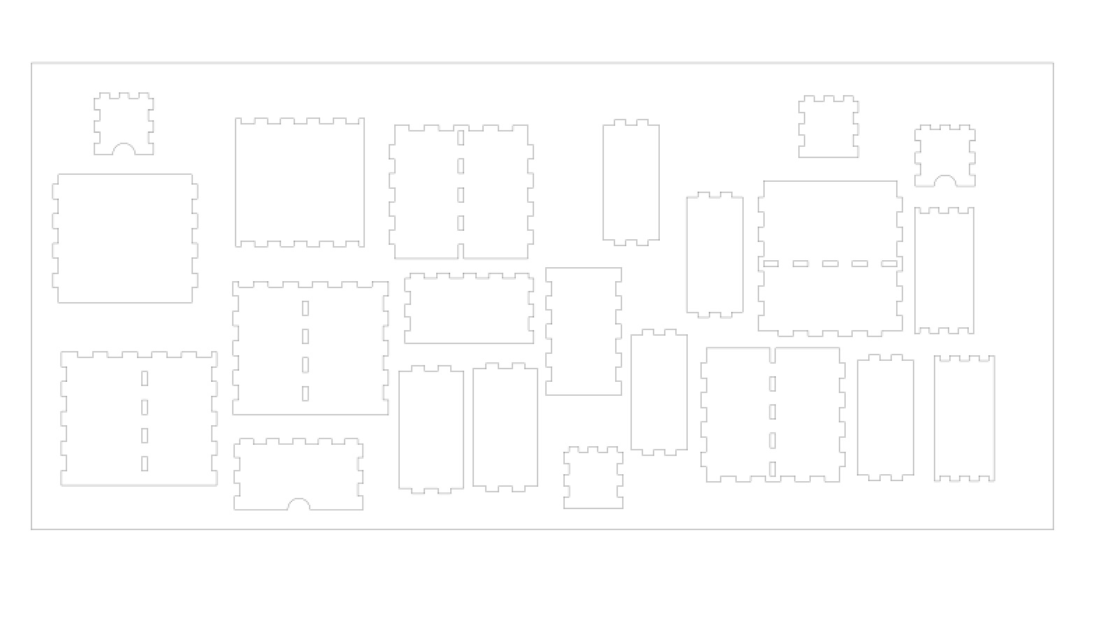
Something that I discovered while working on Fusion this week is how to lay all the parts flat and then create a sketch to export as a dxf. I first made a box that was about the size of the stock. Next, I created components from all the bodies and then made a planar assembly joint between the stock and all the components so that it laid flat. This made exporting much easier.

Exported DXF file:
When I got to the lab, I realized that we had some 0.25 inch stock. I thought about using this since my storage drawer is pretty small. So I changed the ply thickness on fusion to the thickness of the stock which was about 0.24 inch.

I decided to go with the 0.25 inch stock and screwed it to the bed of the mill.
Vcarve and Shopbot
I opened my dxf file on V carve and started setting up my toolpath. The first thing you do is set the job position and zero. NExt you enter the thickness of your stock, select the correct zero, and put in the right cut depth. You make the appropriate selections for the toolpaths and then save the it. Since the smallest tool diameter that we have is 0.25” and the stock is thinner than that, the toolbit couldn’t cut out some of the pockets. Fixing this issue took a chunk of my time. I was constantly going back and changing dimenisons. Finally, I decided to change the thickness of the stock to 0.25 on Fusion. That was the only way that the machine would create a toolpath through some of the holes.
Before opening the file on shopbot, make sure to preview it. I caught a scaling issue thanks to preview.
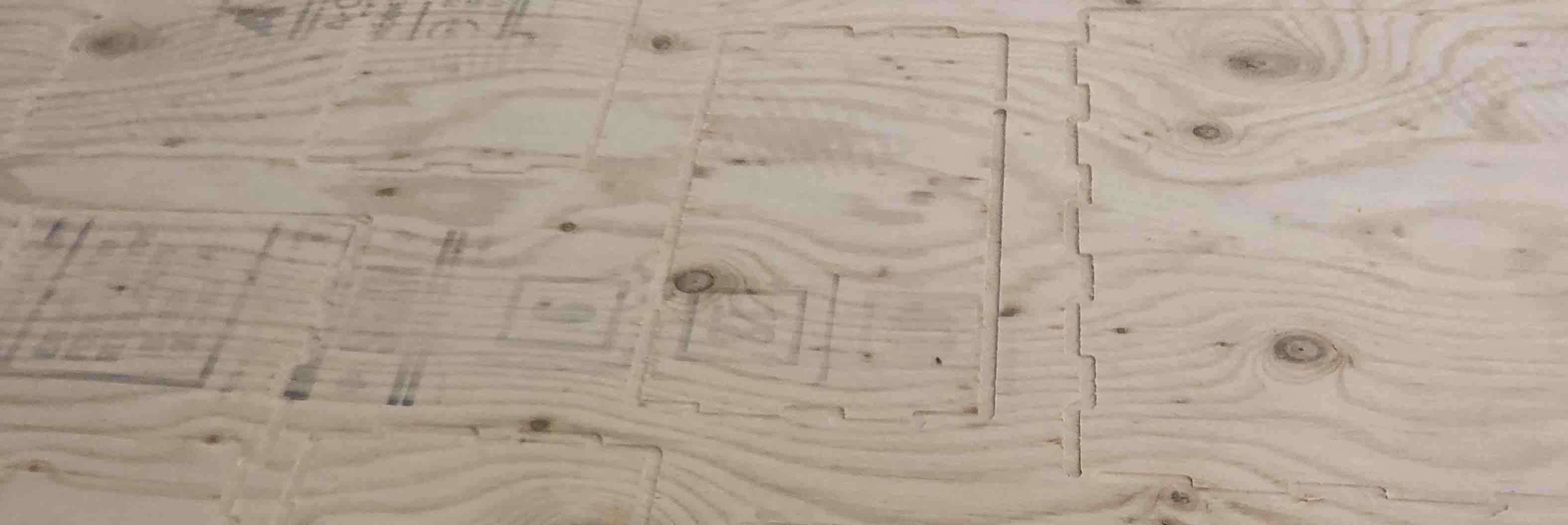
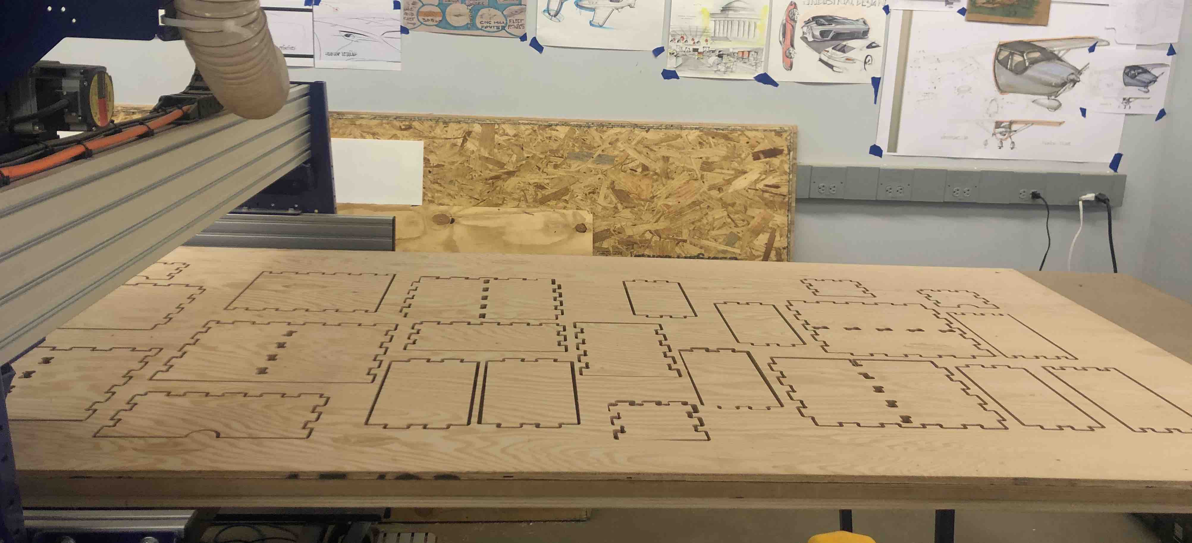
Next, open up shopbot and zero the axes. Load your toolpath and run it. Since the stock that I used was flimsy, I decided to trace my cut first by setting the cut depth to 0.1” and then put screws in the spaces.
Since the material is pretty thin, I decided to skip adding dogbone fillets. BAD decision.
Anyhow, the job ran successfully and I had my cut pieces.

Time to sit down and put the pieces together:
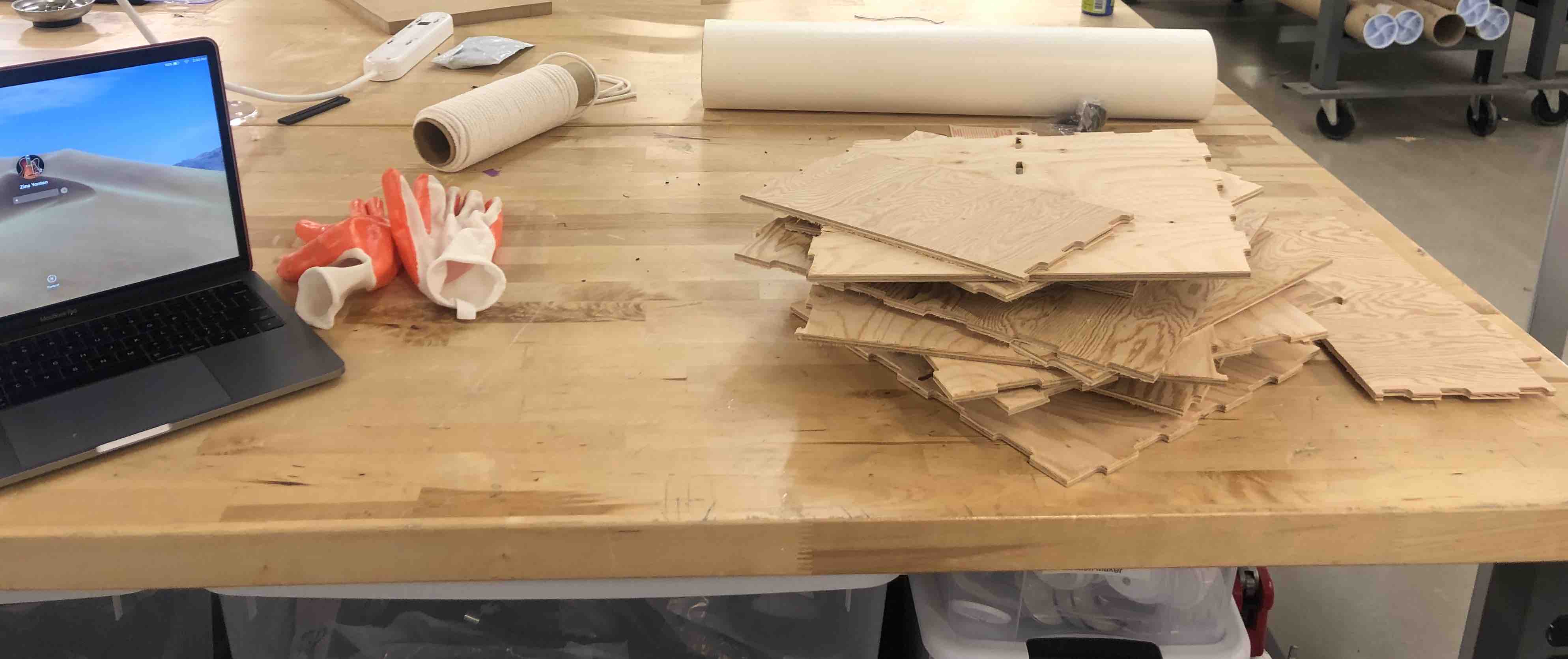
I was ready to assemble everything except everythinbg refused to get assembled. This try had multiple problems: 1) Very thin material, didn’t really stay together. Better suited for laser-cutting. 2) No dogbone fillets so things didn’t fit right.
At this point I wondered why I hadn’t just done a simple bookshelf. Anyway, I decided to do another try with the 0.5” stock and things ran much smoother. First up, I changed the thickness on Fusion. Next, I took the updated DXF file to Vcarve and made the appropriate toolpaths. Remember to put in tabs and DOGBONE FILLETS. The stock was MUCH sturdier and I did not have to put any addtional screws in the middle of the stock to hold it down.
The cut was very clean. This is probably because I used the downcut bit.
Time to assemble! I already had a good feeling about this:
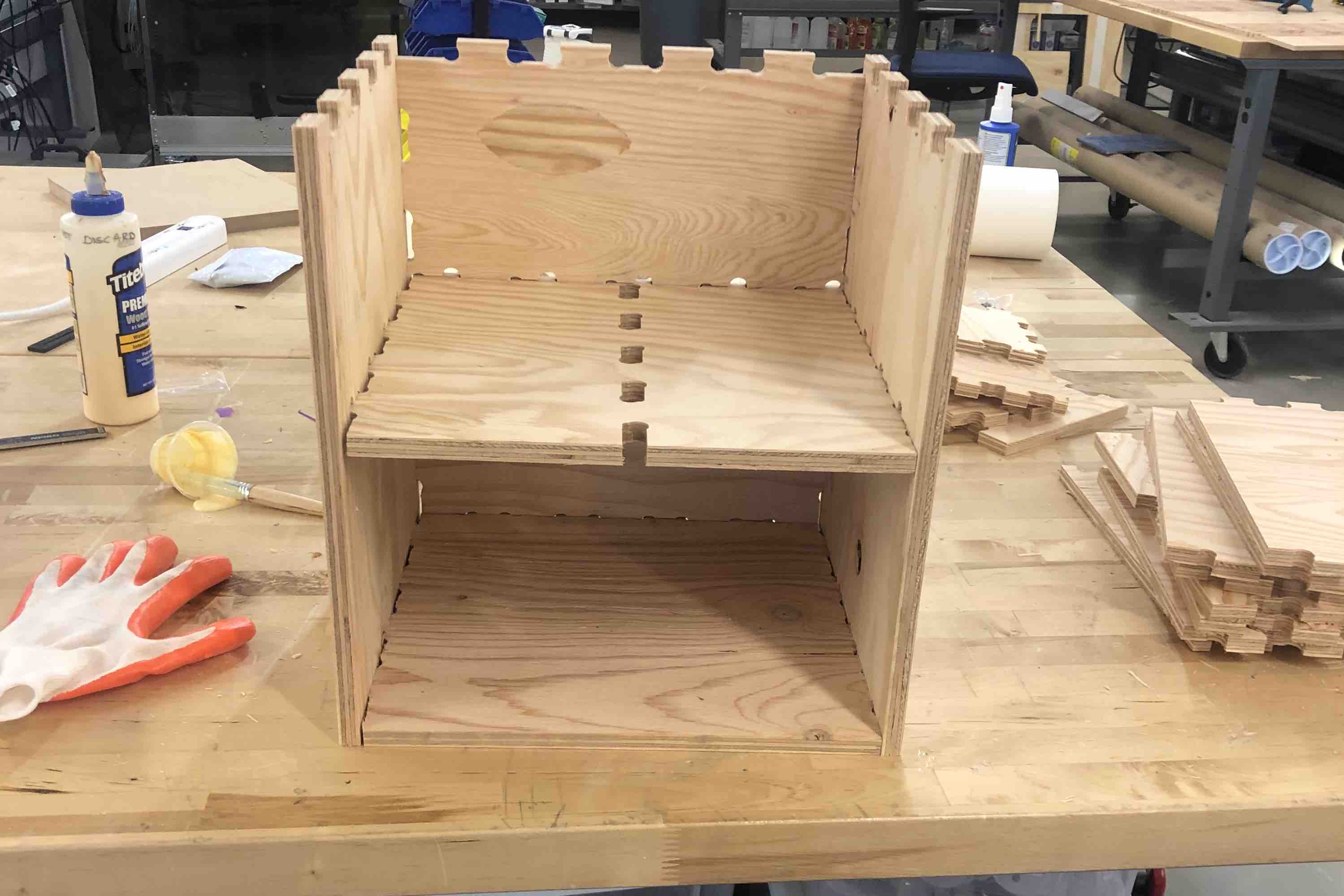
It was going well until I realized that I had forgotten to add dogbone fillets to the pockets on one of the wood panels.

Aboudy, one of the Fablab interns, told me that we could either make the pockets bigger or file the corners. I decided to file and it worked.
The rest of assembling went pretty well.

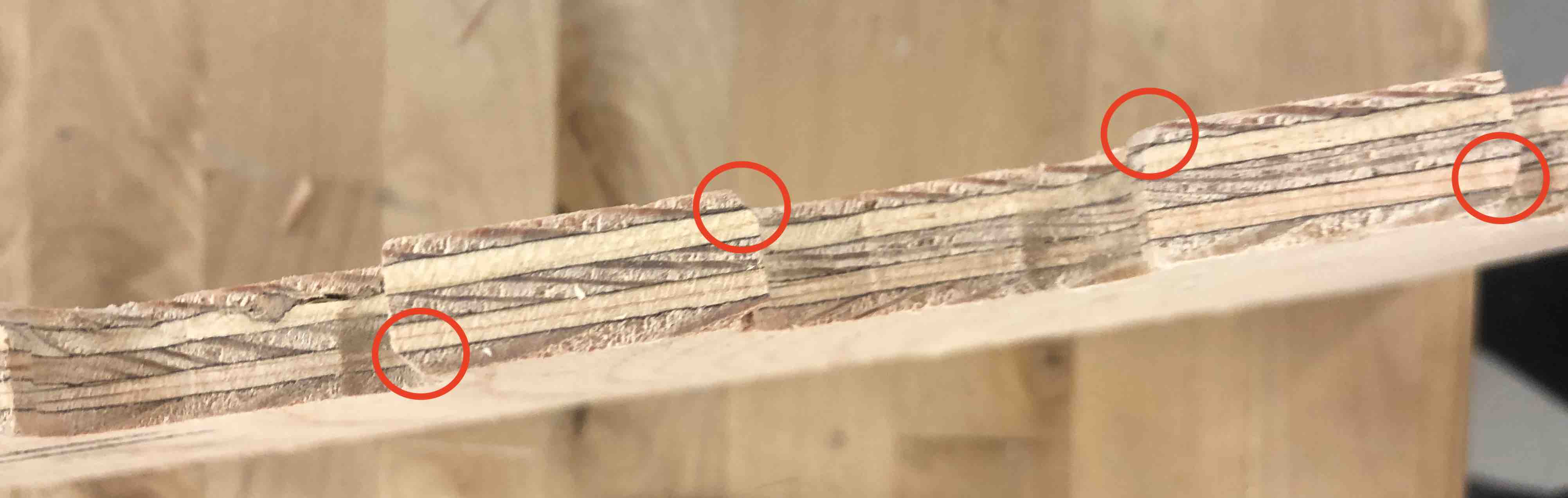
Although everything assembled without the use of any addtional material (screws, nails, glue), some of the joints were loose.

Download Files
Useful links
Assessment Guide
Linked to the group assignment page
Documented how you designed your object (something big)
Documented how you made your CAM-toolpath
Documented how you made something BIG (setting up the machine, using fixings, testing joints, adjusting feeds and speeds, depth of cut etc.)
Described problems and how you fixed them
Included your design files and ‘hero shot’ photos of final object