6. Electronics Design
This week started with a short introduction to the various components that go in our circuit boards. We redesigned the echo hello-world board and added a LED and button to it. The goal was to get the LED light to blink in an infinite loop. I used Eagle to design the circuit. Once my circuit was designed, I exported the traces as a PNG file so that mods can read it to cut it. Once this was done, I stuffed the board and programmed it on Arduino using a USBtinyISP and IT WORKED!
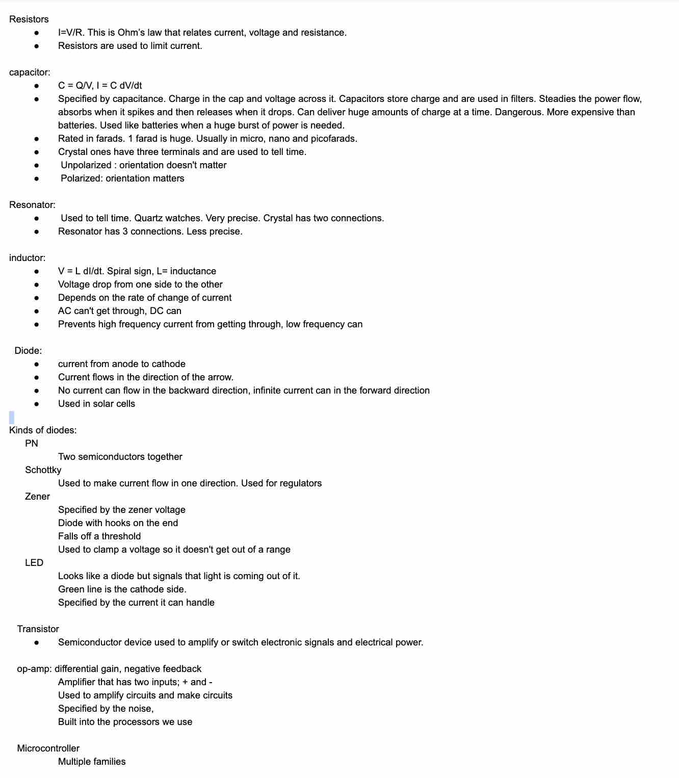
Board Components
EAGLE
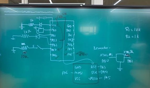
This picture is helpful while making the connections:
EAGLE (Easily Applicable Graphical Layout Editor) is a flexible and expandable EDA schematic capture, PCB layout, autorouter and CAM program. It is popular among hobbyists because of its freeware license and rich availability of component libraries on the web. I started off the week by attempting a tutorial on EAGLE. I tried tutorial 7.1 on the Fabacademy website.
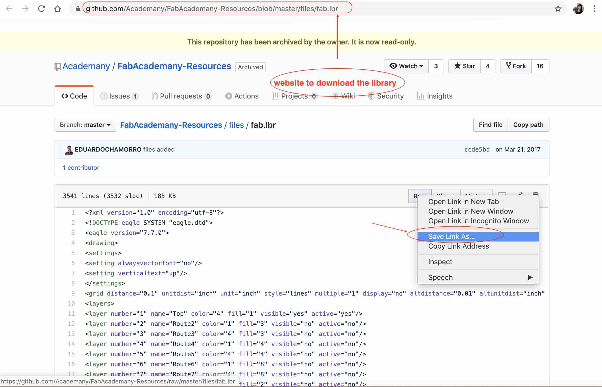
After downloading EAGLE, we need to download the fab library of components so that we can include the components we have in the lab in our design. To download it, go to the appropriate link and then right click on “RAW” and click “save link as.” Ensure that the location is in the Library folder in the EAGLE file and that the file extension is .lbr.
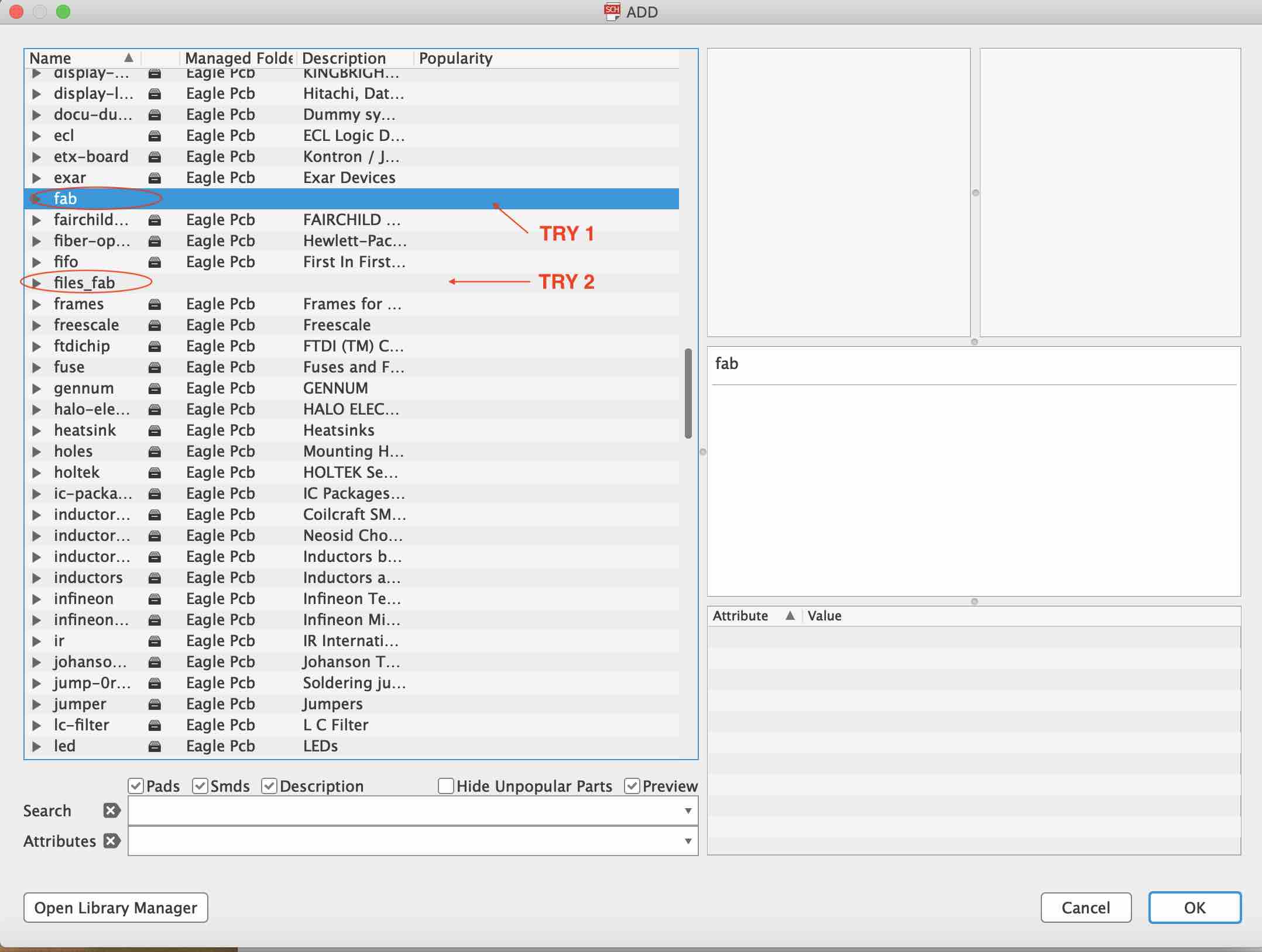
Once downloaded I tried to add components to my design. This is where I ran into Hurdle #1. Although I had downloaded the .lbr file and added it to my EAGLE folder, I couldn’t find the library at all when I wanted to add components. I finally figured that you had to add the fab.lbr to the library on EAGLE.
Go to Library -> Open Library Manager -> Availible tab -> select fab.lib -> click Use
This will add fab.lbr to the library. Finally, when adding components, make sure to scroll down and look for “fab”. Since there are a lot of default components, it is easy to get lost (like me) and think that the folder did not add. Because of this, I ended up downloading and adding the library twice.
Now, you can start designing the circuit. Open a new project, and a new schematic. Start by adding components. Here is the list of components I used:
- 01 X ATTiny 44;
- 01 X FTDI Header;
- 01 X AVRISP (2X3 Header);
- 01 X Ceramic Resonator;
- 02 X 10k Resistors;
- 02 X 0 ohm Resistors (as jumpers);
- 01 X 100 ohm Resistor;
- 01 X 1uF Capacitor;
- 01 X LED;
- 01 X Button/ Swtich;
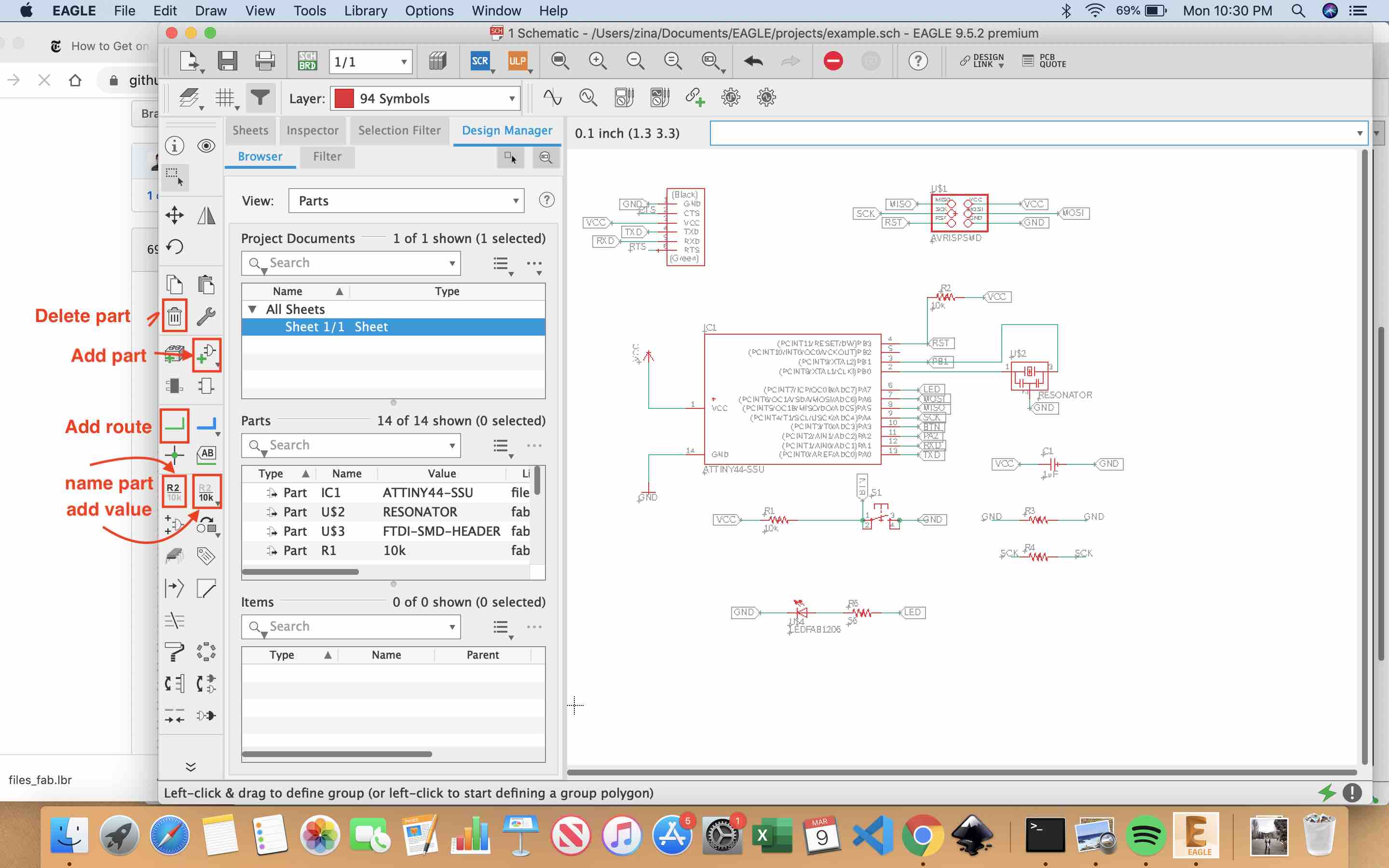
Next, route the connections. Something that is really nice with EAGLE is that you can name the connections and it will connect like-named connections. This makes the circuits so much cleaner. Here is a picture of my schematic with the four most used buttons:
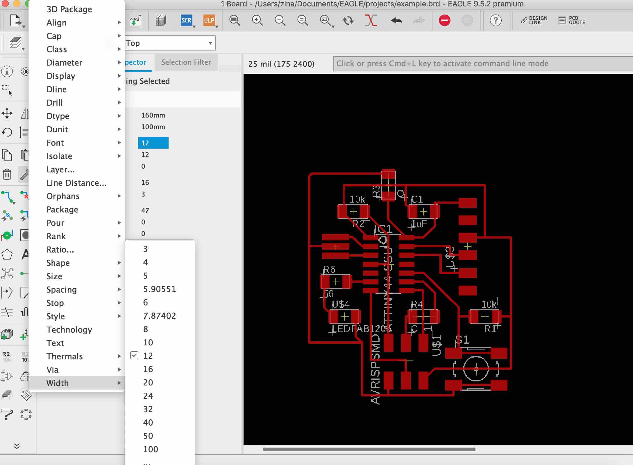
Once you are done with the schematic, you can switch to the board view. The board view changes as you change the schematic. When you first open it, it will be a giant mess.
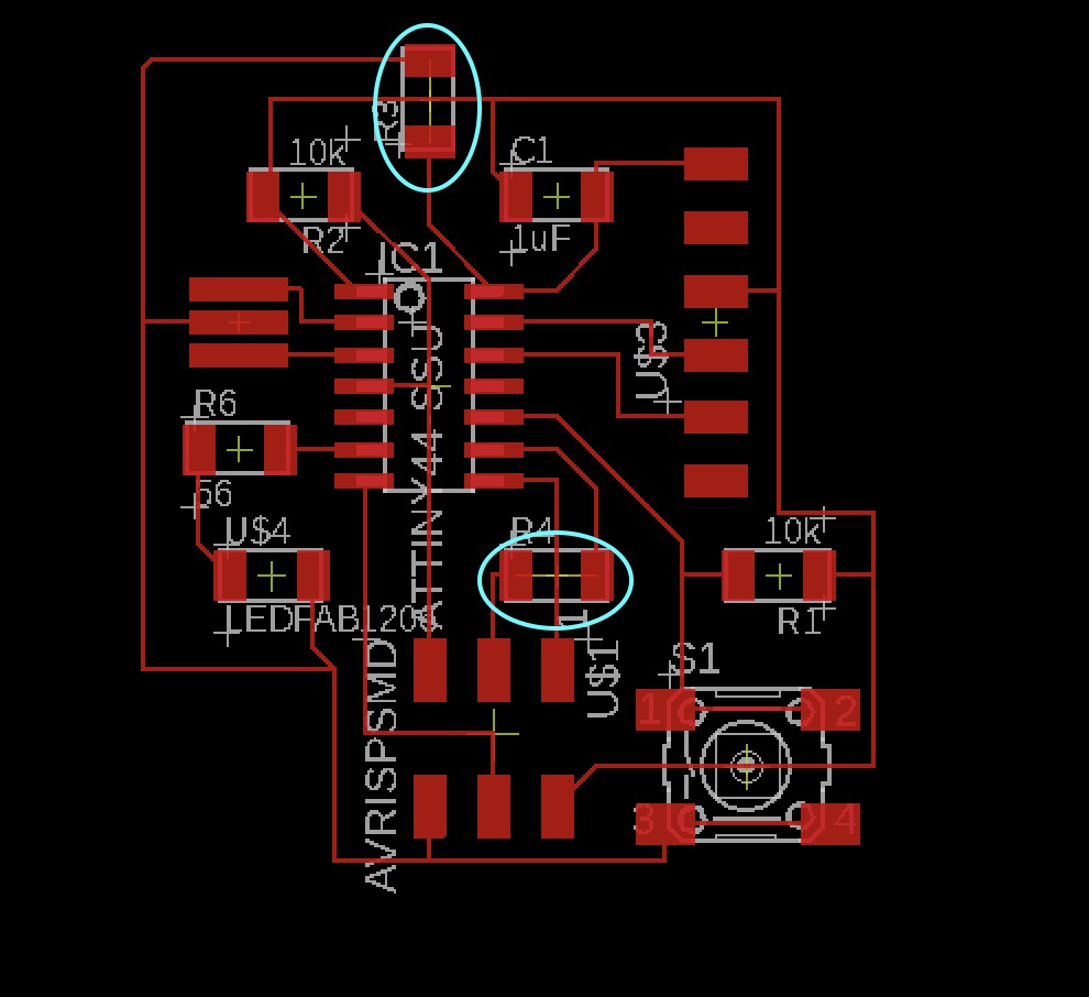
BEFORE you start routing anything, be sure to change the width of the route from 6 to 12. This is ensure that the traces are thick enough. Here is a picture of my final board with the width set to 12:
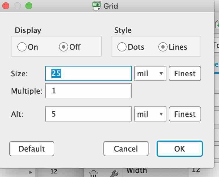
Also be sure to change the grid to 25 from 50. This will give you more freedom to place the traces.
IF there are certain connections that you cannot make without crossing another trace, you can add 0 ohm resistors that act as “jumpers.” These essentially “jump” over a trace. I have two in my connection:
Once the board is ready, we need to check that the endmill we are using (1/64 usually) is able to go between all the traces so the machine is able to cut the board successfully. For that we use Design Rules Check (script) that checks that there is enought space everywhere.
After downloading the script here, we run the check on EAGLE:

|

|
From the picture above, you can see that I had 3 airwire errors. This means that there are three connections that I have not made on the board. On checking my board, I realised that this was because the board wanted me to connect the two ends of the 0 ohm resistors. I know that this is not needed so I decided to ignore the errors.
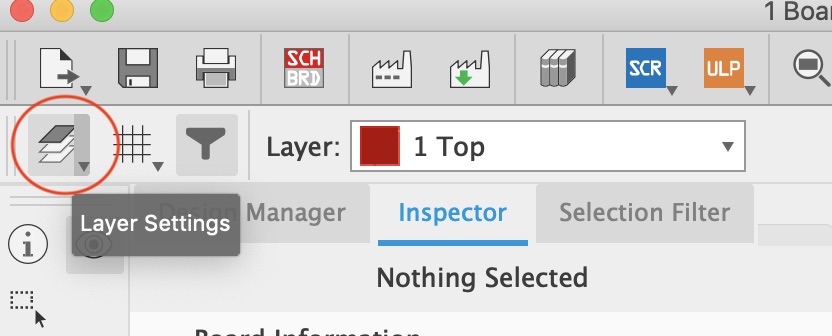
The board is now ready to be exported as a PNG image. To do this, we have to make only the top layer visible. Go to layer settings and deselect every except the top layer:

Once you have the desired image to export, follow these steps:
Files -> export -> image -> select location, set resolution to 500 DPI and check monochrome.
Mac has a bug that exports the wrong size image from eagle so I opened my board on a windows computer and exported the image.
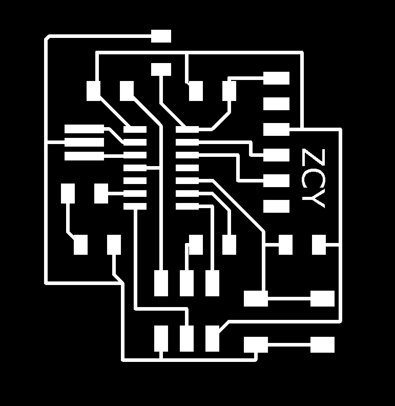
Open the saved image on a image editing software and crop it. You can also add some customized text here. I added my initials. Next, make an outline and fill it to create the cut image. Save as a PNG file.
|

|
The board is now ready to mill.
Milling and Soldering
This part went pretty well. I followed what we learned in week 5. Here is my milled board:

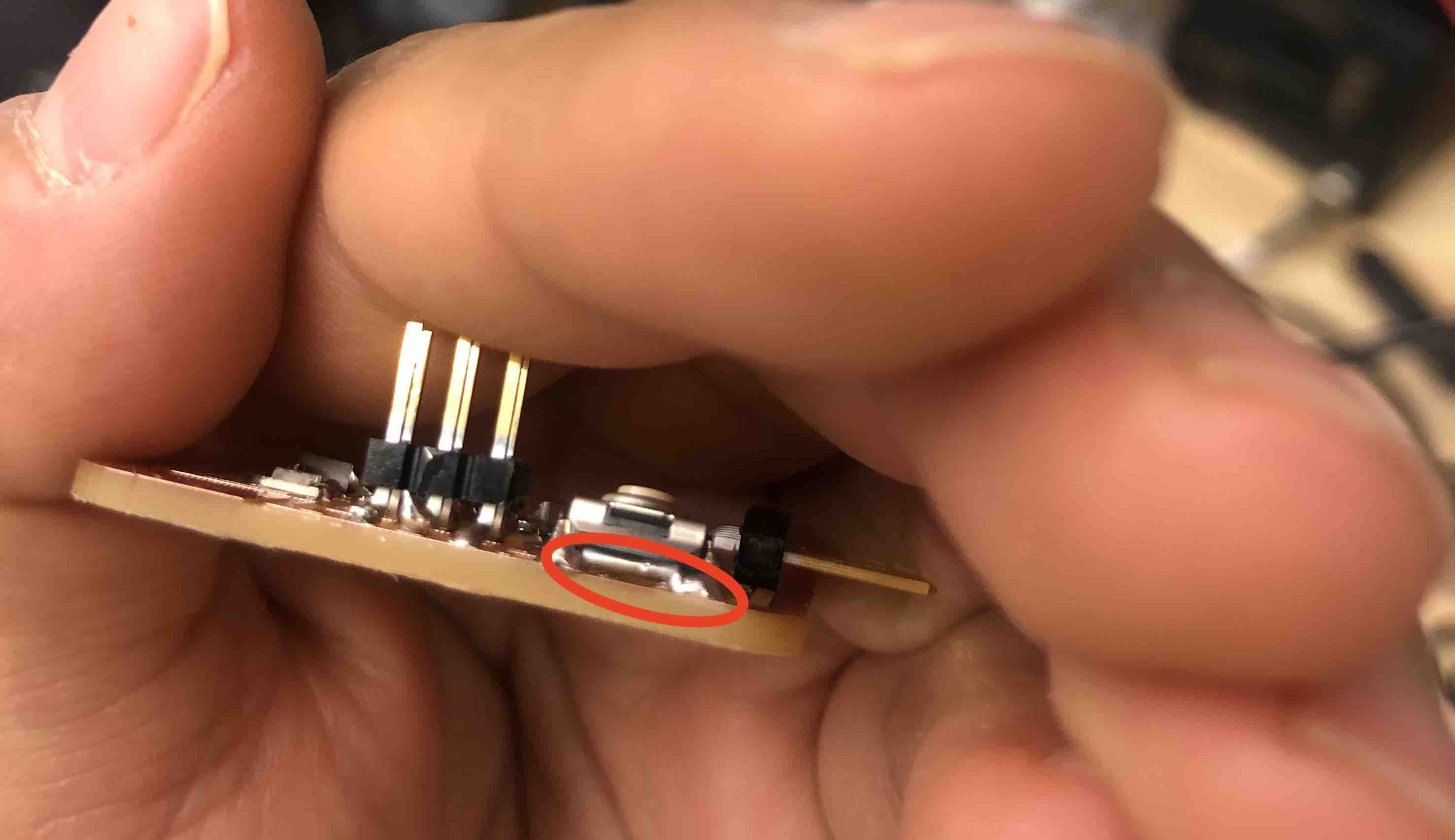
However, while soldering, I accidentally ripped up the trace that runs under the buttons. It was pretty late in the day and I knew that there was not enough time to mill another one. So I tried to solder on a connection. This did not work because the oil on the board made it impossible to solder on the cut part. Experiment time. I cut a piece of solder wire about the length of the trace that I ripeed up and soldered the ends on.

I hoped that the button would solder on, and it did, even though it was a little lopsided.
Here is my completed board:
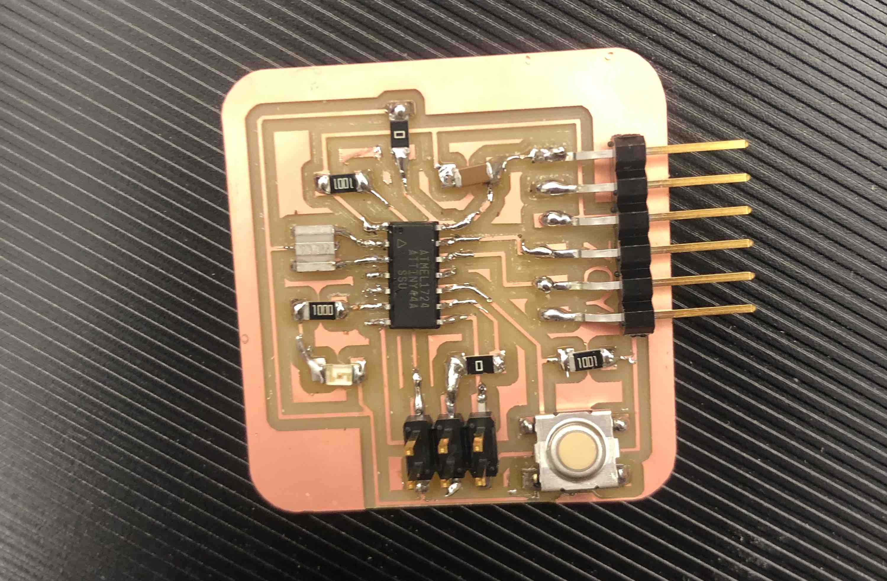
I realised while soldering that I had forgotten to wash my milled board. There was still some oil on the board and this made it hard to solder. ALWAYS REMEMBER TO WASH THE BOARD BEFORE SOLDERING.
Programming
With the finished board, it is now time to program it and check if it works. I was almost sure it was not going to becuase of my solder trace, but I continued since there was nothing to lose.
The first step is to download Arduino on your laptop. Next, install ATTiny support on Arduino. Details are explained on this website. Using the built in board manager paste the following link:
https://raw.githubusercontent.com/damellis/attiny/ide-1.6.x-boards-manager/package_damellis_attiny_index.json


Provide power to the ATtiny and connect it to the Programmer (FabISP). Make sure that the MISO, MOSI, SCK, RESET, VCC, and GND of the Programmer is connected correctly to the corresponding pins on the ATtiny. Next, connect the FabISP to the ATtiny using the ISP header. Finally connect the FabISP to the computer’s USB port and power the ATtiny using an FTDI cable.
I used my instructor Greg’s USBtinyISP since mine got damaged.

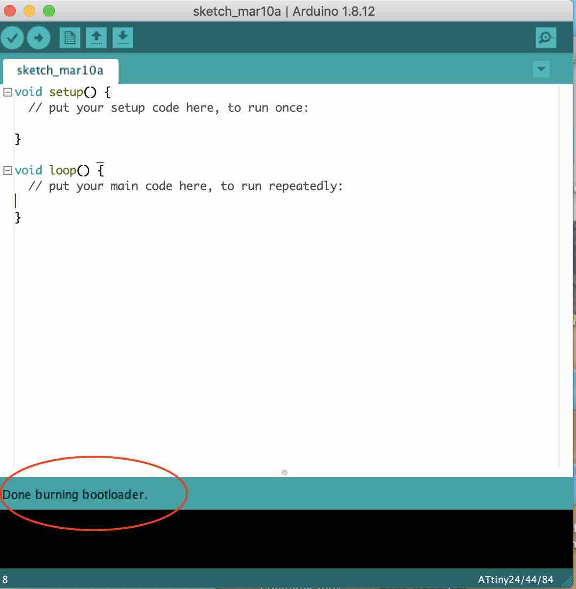
Under the tools menu, update the Programmer (USBtinyISP), Board (ATtiny24/44/84), Processor (ATtiny44), and Clock (External 20 MHz) and run the Burn Bootloader command which configures the fuse bits of the microcontroller. You only need to do this step once for the microcontroller. This doesn’t actually burn a program code onto the board; you’ll still need to upload new programs using an external programmer in the future.

I was happy the bootloader actually worked on the first try. :)
Finally, I programmed my board to blink on Arduino. Remember that the pins in ATtiny44 are not the same as in an Arduino, we have to use a chart to convert the pins:

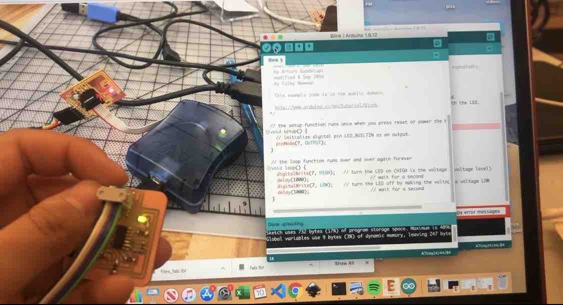
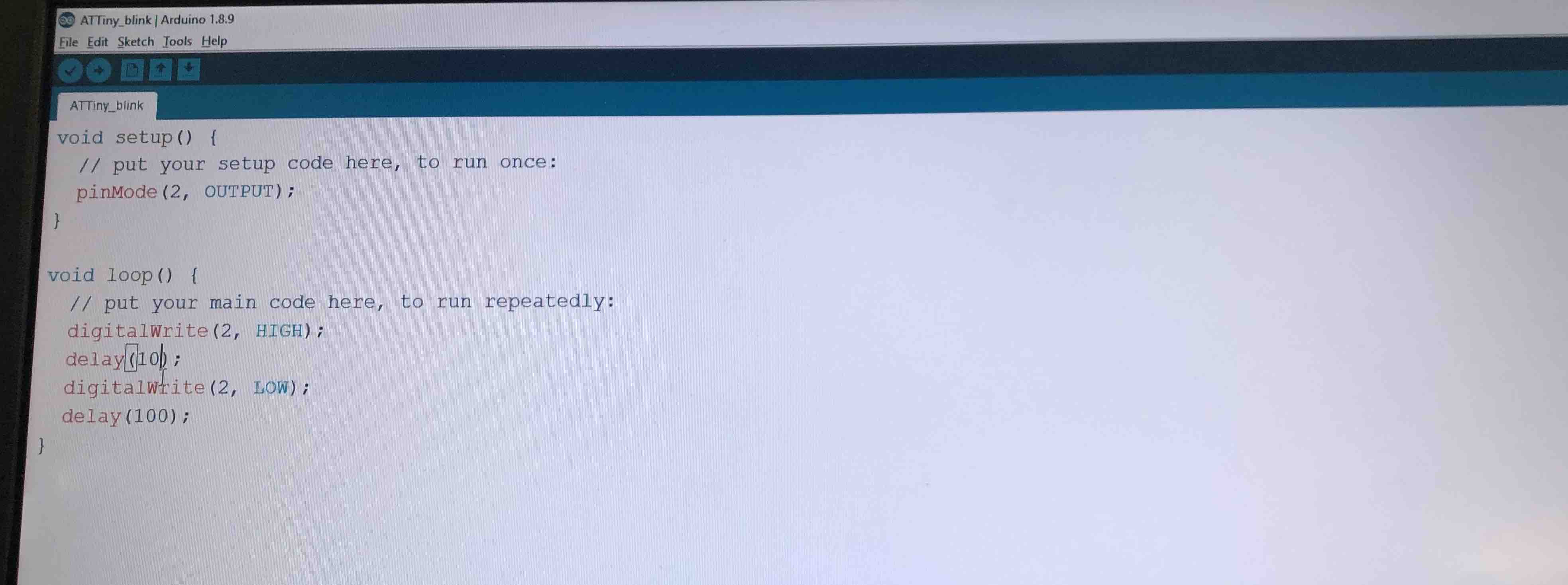
In the arduino command space, click open and select blink.

Change the “LEDBUILTIN” to “7”

|

|
Run the code and viola! The LED blinks! I wasn’t able to code the button though.
Useful links
- Felipe Santos Gomes, 2019 Fabacademy
- Saba Ghole, 2018 Fabacademy
- Fabacademy tutorial 7.1
- Youtube eagle tutorial
Group Assignment
For the group project, Nicholas, Spencer and I ran a code on a board Nicholas had and and measured the voltage across it using an oscilloscope.

Nicholas ran a blink code across it.
The results were as expected:
Download Files
Assessment guide
RLinked to the group assignment page (Done on this page)
Documented what you have learned in electronics design
Explained problems and how you fixed them, if you make a board and it doesn’t work; fix the board (with jumper wires etc) until it does work.
Included a ‘hero shot’ of your board
Loaded a program and tested if your board works
Included original design files (Eagle, KiCad, - whatever)