3. Computer controlled cutting
This was a very intense and interesting week. It was the first week with hands-on learning. We started with the vinyl cutter. It was great to learn how to make my own stickers. Next, we moved on to laser cutting which took up the biggest chunk of time and energy. I used Fusion360 to create my 3D models and then converted it to dxf for the laser cutter. I had fun learning the different settings of the laser cutter and how each color cuts or engraves differently. The highlight of my week was being able to make a 3D model of a bag using living hinges for my final project.
Vinyl Cutting
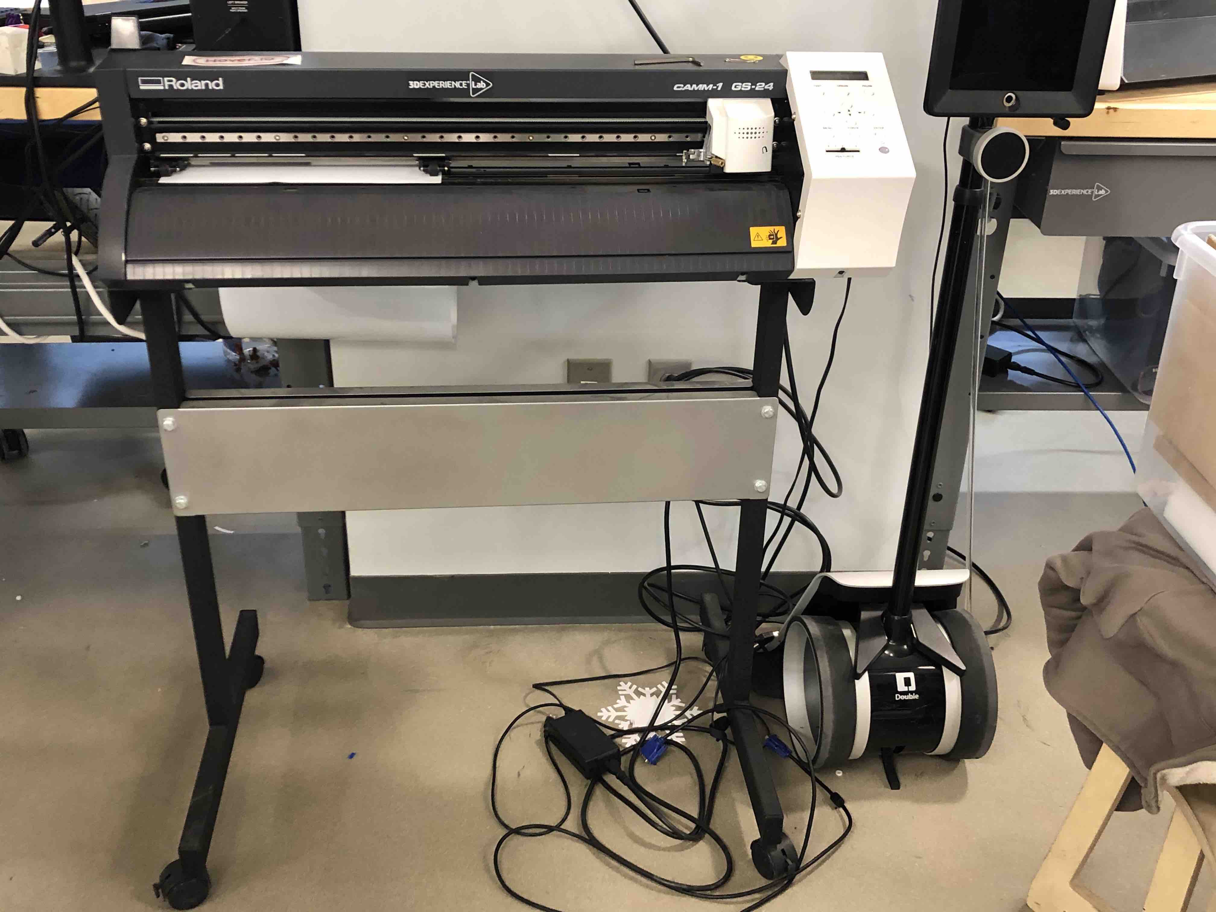
Part of the assignment for this week was to cut something on the vinyl cutter. Neil mentioned that cut-out stickers is a very popular option. Our mentor Greg demonstrated how to use the vinyl cutter. The one that we have in the Dassault Systemes Fablab is a Roland CAMM-1 GS-24:
To set up the machine for cutting:
-
Open cutstudio. This is the sofware that is connected to the cutter
-
Go to file -> cutting setup. Set the setting to “from machine”
-
Download your image and drop it on Cutstudio
-
Right click on image and select image outline
-
Check machine settings
-
Go to file and click cut
Loading the vinyl sheet:
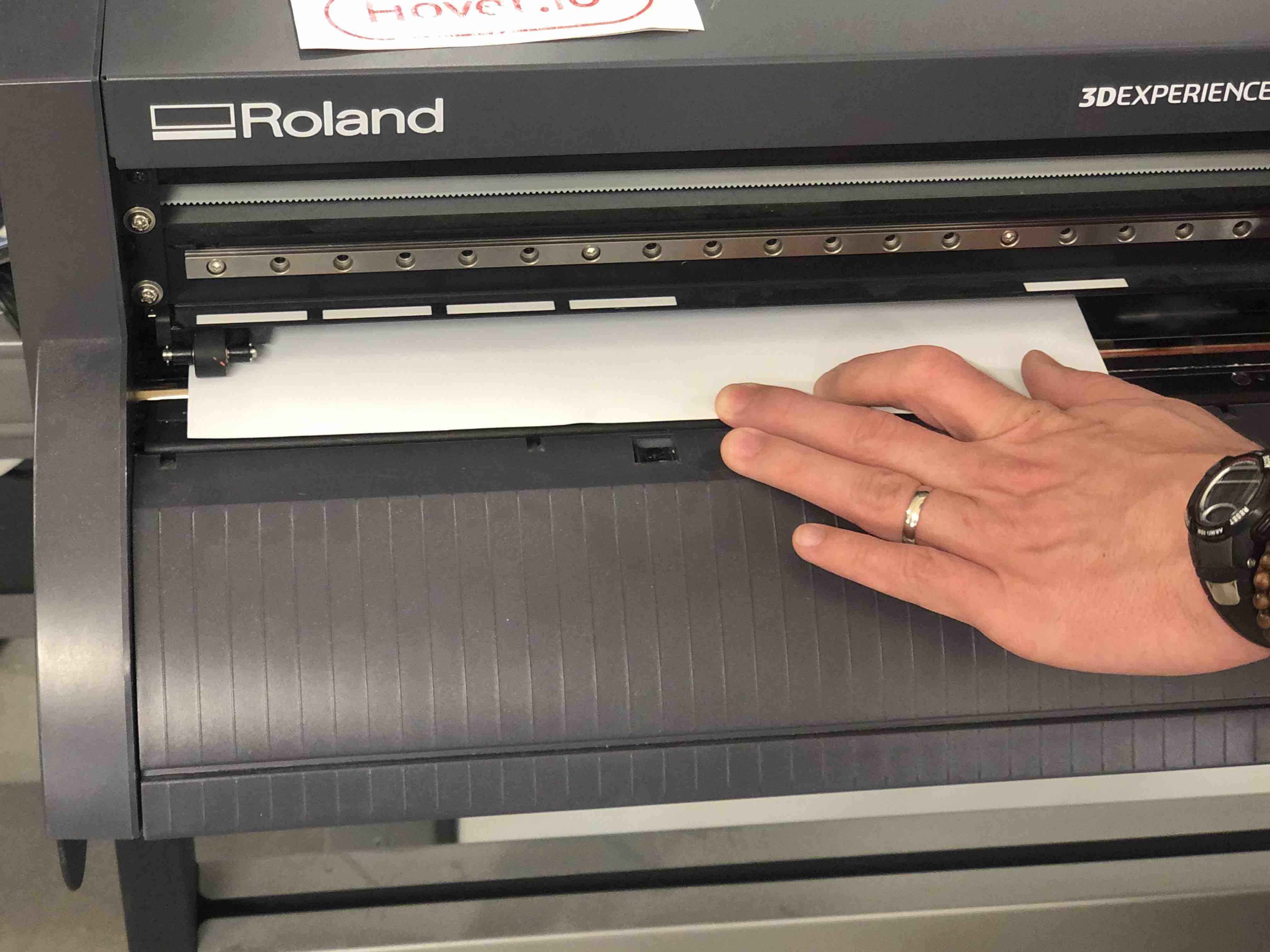
Before starting, we had to change out the blade from the vinyl cutter since it was blunt:

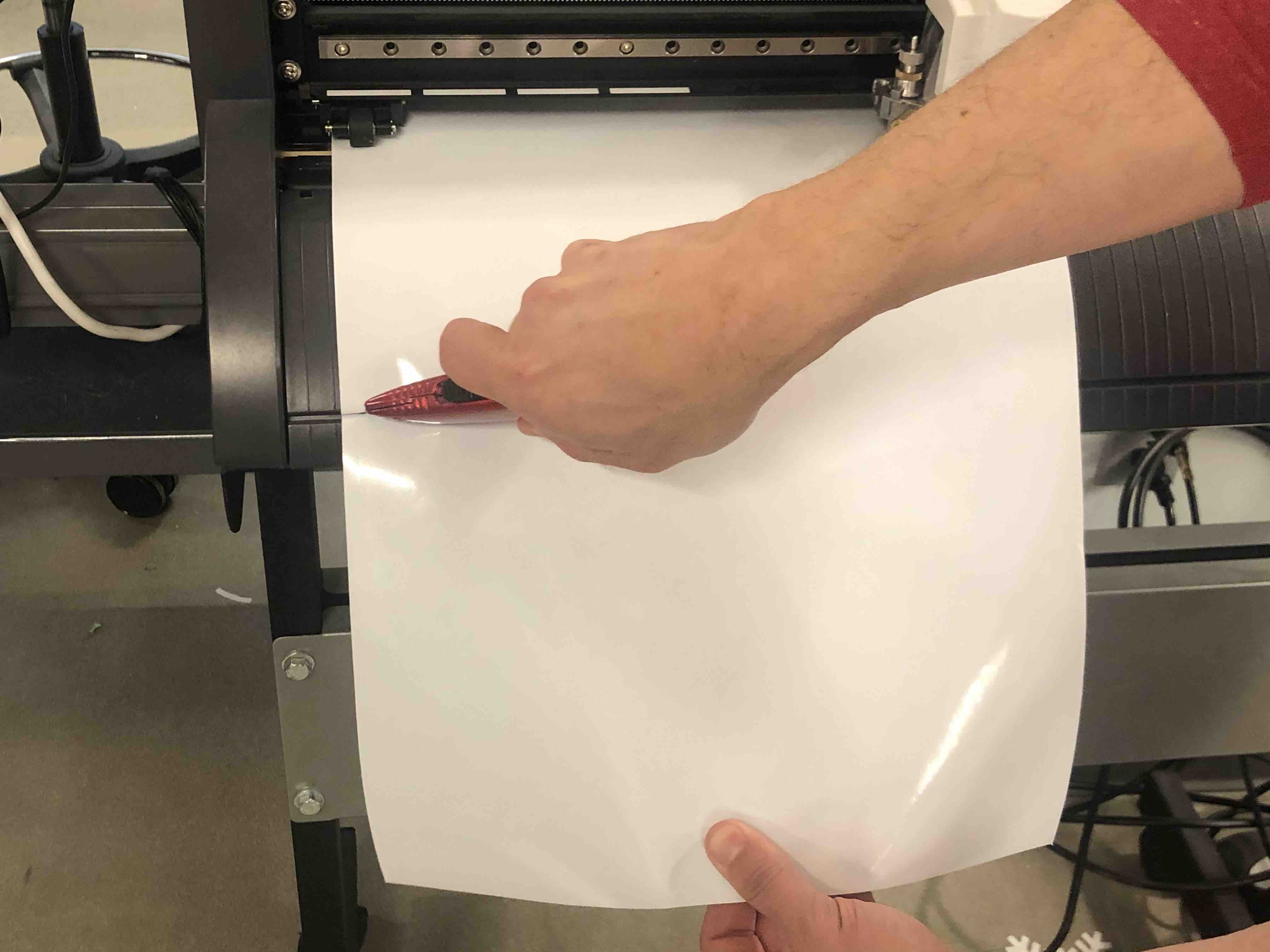
After cutting, we have to press menu on the machine twice and click unsetup. This resets the machine to default settings. Finally, we cut our portion of the vinyl sticker from the roll:
Next, we pull out the parts of the stickers that we don’t want. We then take some transfer tape and put it on the sticker. Make sure that there are no air bubbles. Finally, we take the sticker and press it down on the desired location. We decided to redecorate the vinyl cutter.

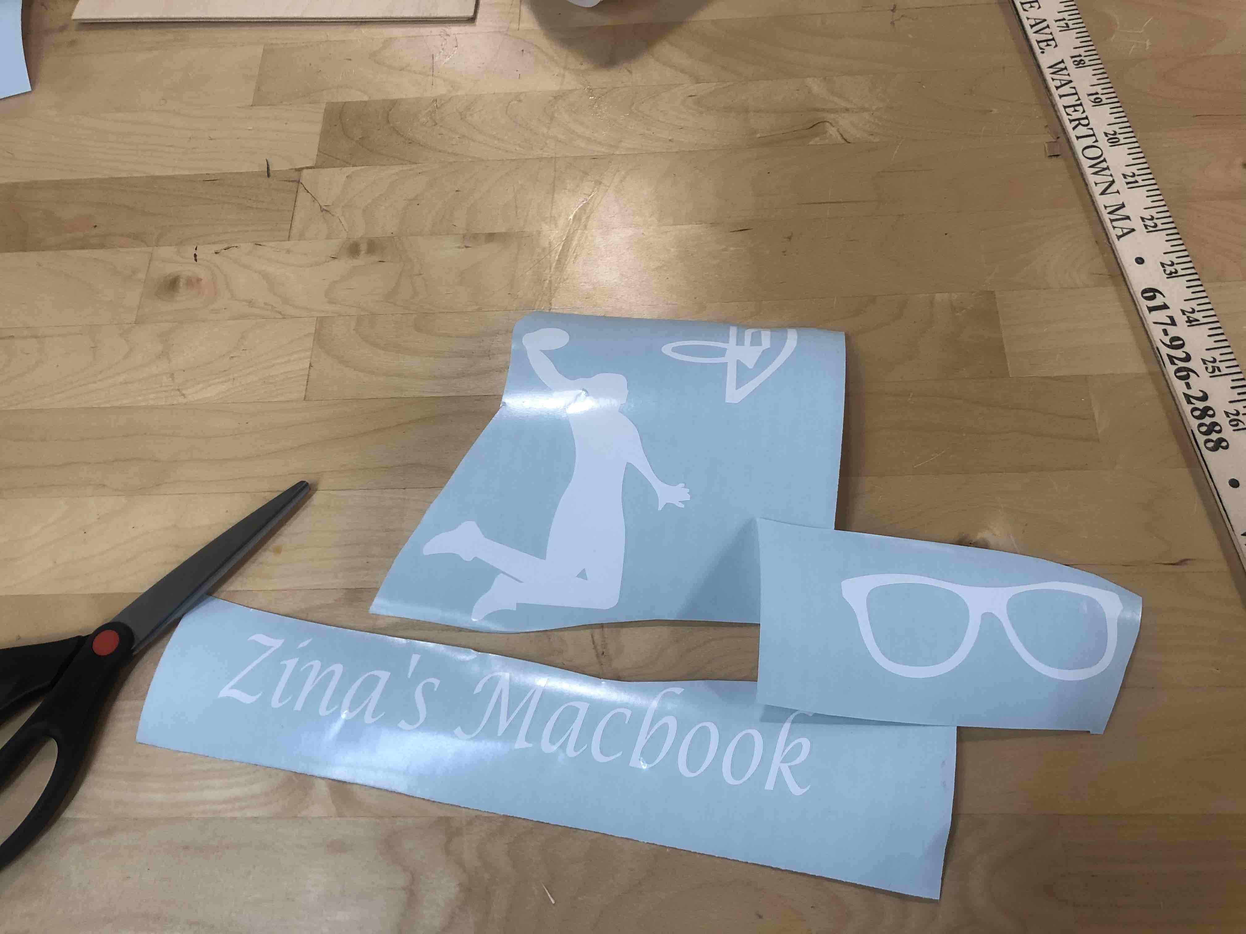
The demonstration was really great and I looked forward to cutting out some of my own designs. I downloaded some images from google and decided to covert them to stickers. This is the link where I downloaded the eyeglasses image.
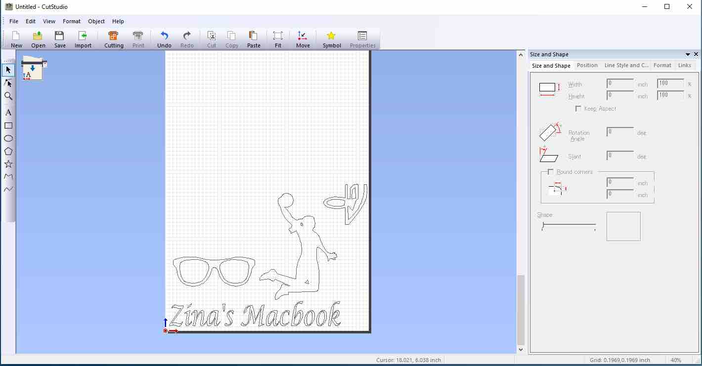
For the text, I just used the tools on cutstudio. Here is the finished product:
Here is a comparison of my laptop before and after stickers!
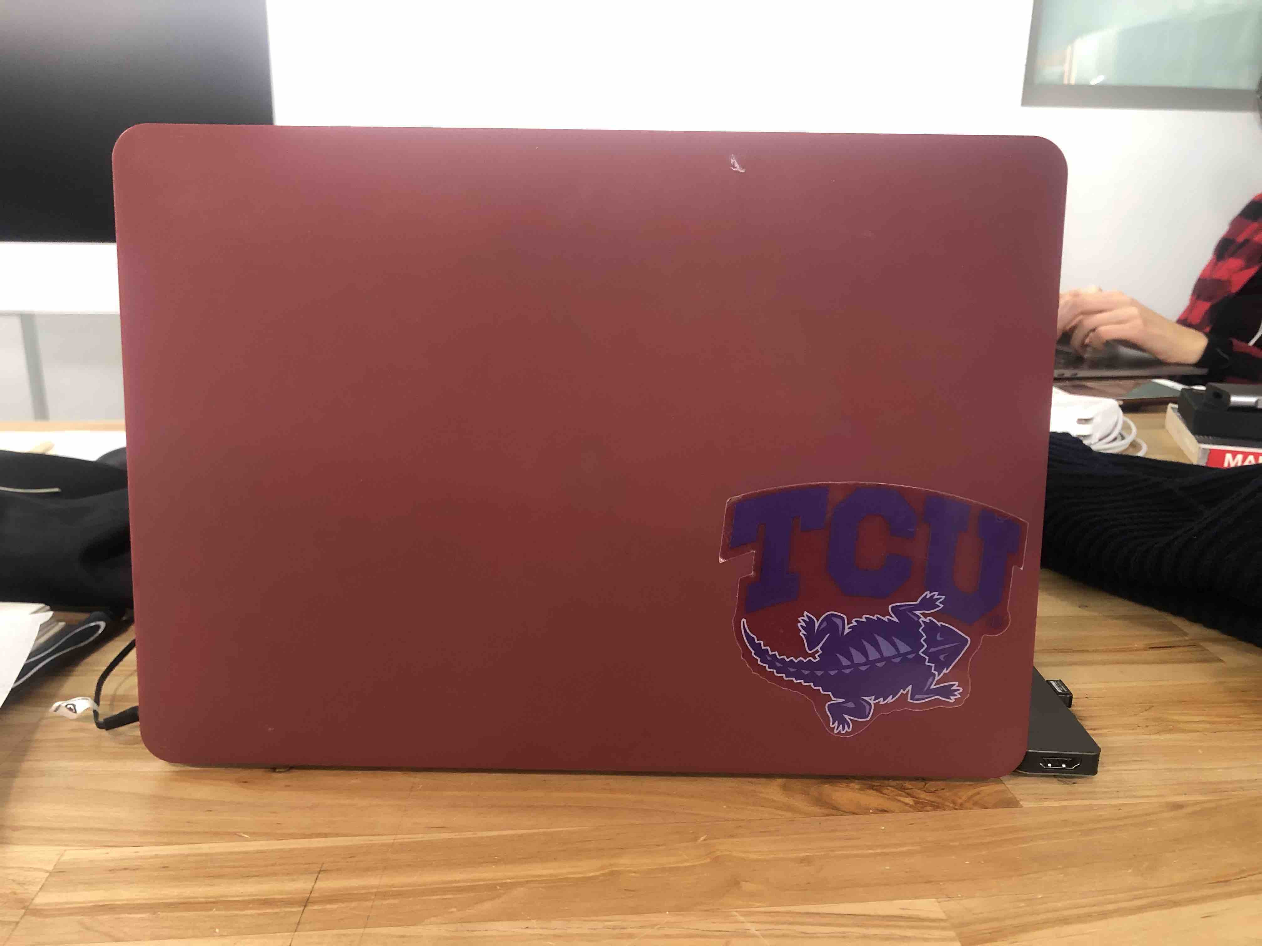
|
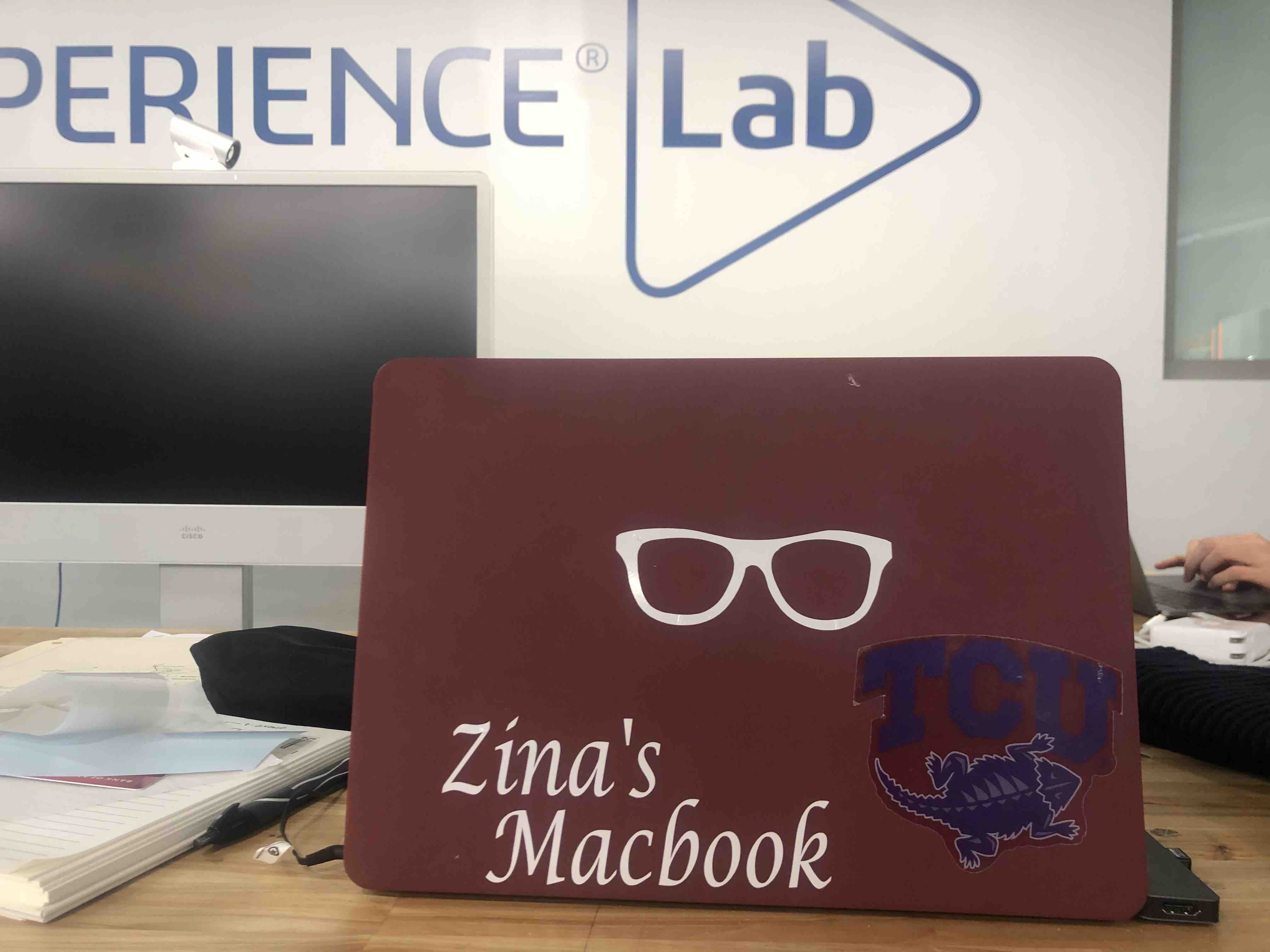
|
Laser Cutting
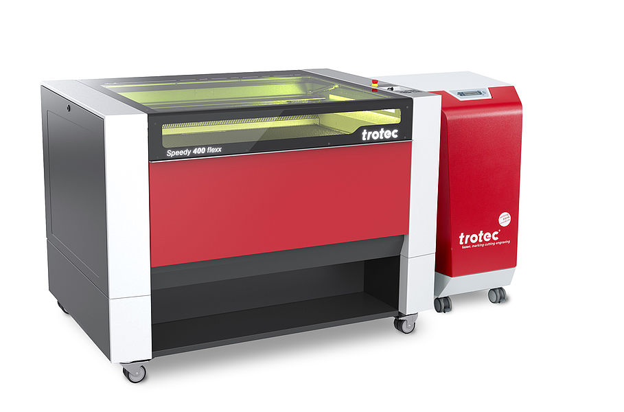
The major portion of this week went into learning how to design and use the laser cutter. The one that we have in the Dassault Systemes Fablab is a Trotec 40 inch by 24 inch.
To design the models for laser cutting, I decided to use Fusion360 since it is great for creating both 2D and 3D renditions of the same model.
Neil mentioned that laser cutters are the most used machines in Fablabs. I did not relate to this since I had never used one. I went into this week ready to learn a somewhat foreign machine.
First things first, I opened up youtube and looked for a tutorial to create a 3D model to lasercut. Fortunately, I found one that was great with not only creating models, but also finger joints and living hinges. I have linked the video here. Although the tutorial was super long and took me a whole day to get through it, it gave an idea for my final project model. The tutorial followed an Autodesk product designer designing a case for his eyeglasses. Here is my result of the tutorial. I made a few changes to personalize it:
After doing this tutorial, I realised that I could change the dimensions and scale up the size of the eyeglasses cover to make a model of a bag for my final project.
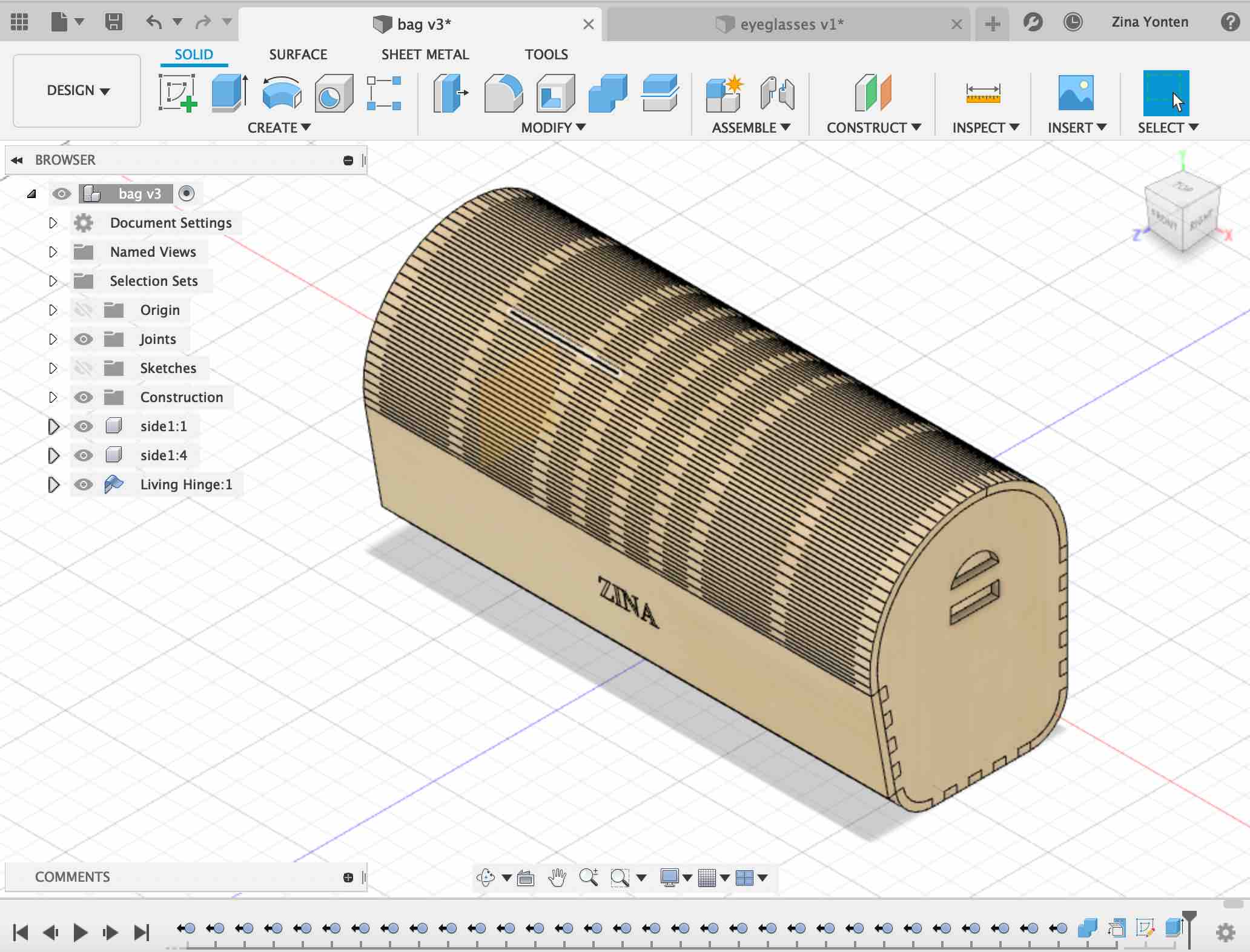
Final Project Contribution
After doing the tutorial for the eyeglasses, I scaled it up to design a bag for my final project. First, I created a base sketch for my bag:

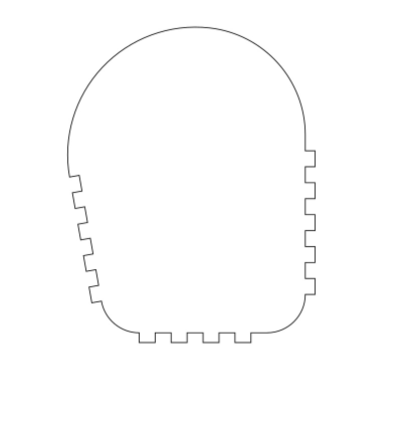
Then I extruded a side component from the sketch. Next, I copied the component to make another side:

Once the two side components were placed at the same distance from the origin, I created a sheet metal part for the hinged component since the sheet metal tool gives you the option to unfold and refold components.

Next, I created finger joints between the two side components and the living hinge component. I did this by extruding ~5mm blocks where the joints would be. Once the blocks were extruded, I used the combine tool to cut the living hinge component. This creates the finger joints:

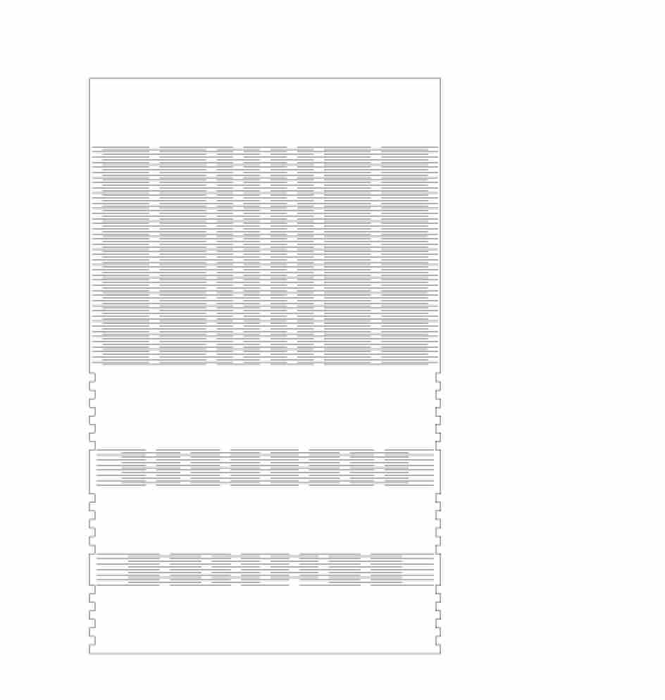
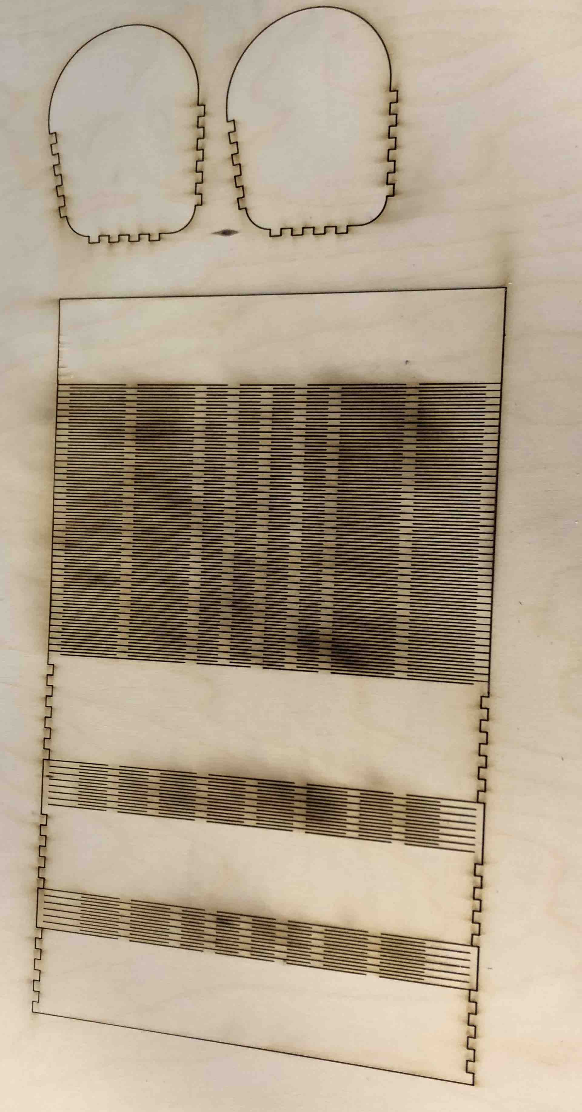
Finally, to finish off the 3D design portion of the bag, I had to cut out the hinges. This was the most challenging part of the week. Creating lattices and then making a rectangular pattern not only slowed down Fusion360, it also made converting the part into a dxf part challenging. Here is the initial sketch which was then patterned:

This is the unfolded view of the living hinge component:

The design turned out pretty good in the 3D design space:

The next step in the process was to convert the 3D components into 2D so that the laser cutter can read it. To do this, I right-clicked on the outline sketch of each component and saved it as a dxf file.
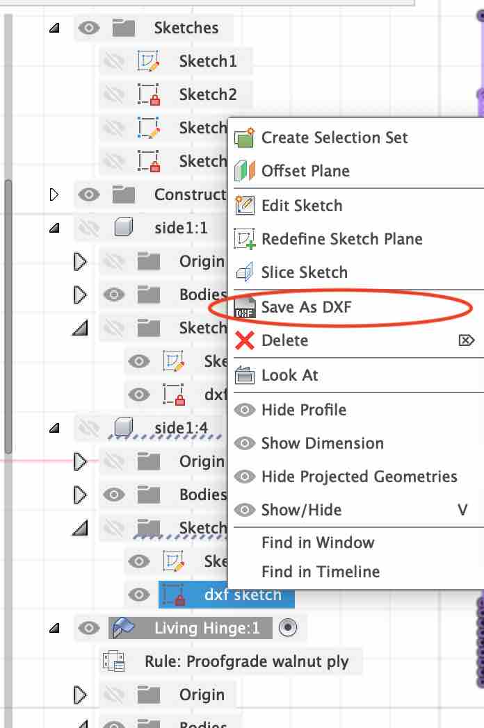
This saves the sketch as a dxf file so that it can open in Illustrator and Inkscape.
|
|
Next we take the files and open it up on illustrator. A few changes have to be made to make the right commands for the lasercutter. The stroke width has to be set to 0.001 inches and the color has to be set to red (cut color). Once everything is set up, the lasercutter works its magic.
|
|
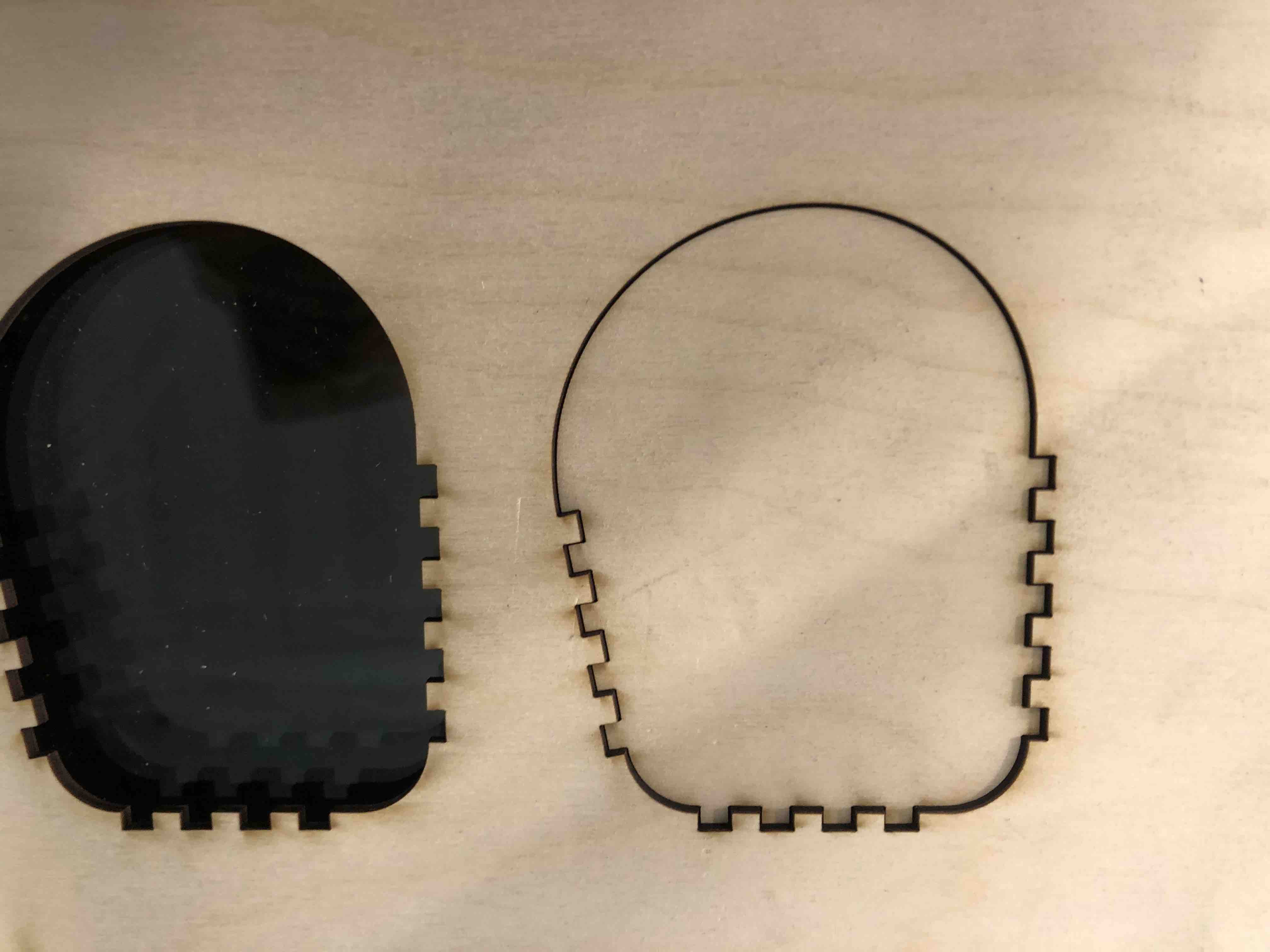
On the first try, the laser did not cut all the way through as you can see from the second picture above. My colleague Nicholas said that it might be due to the lenses. I cleaned out the lenses and tried again. It cut very cleanly all the way through this time.
However, the hinges did not work. They would not bend AT ALL. I force-bent some of them and parts of it broke. Oops.
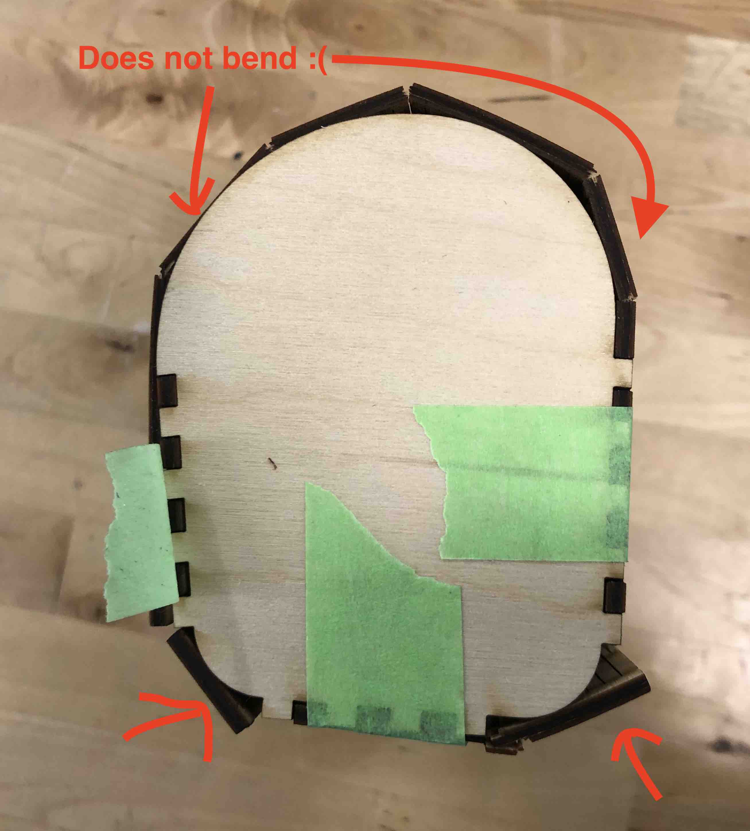

I realized that this was because the cuts of the hinges was not cutting all the way to the edge.

I went back to my work bench and made some edits to my sketch. I cut it out once again.

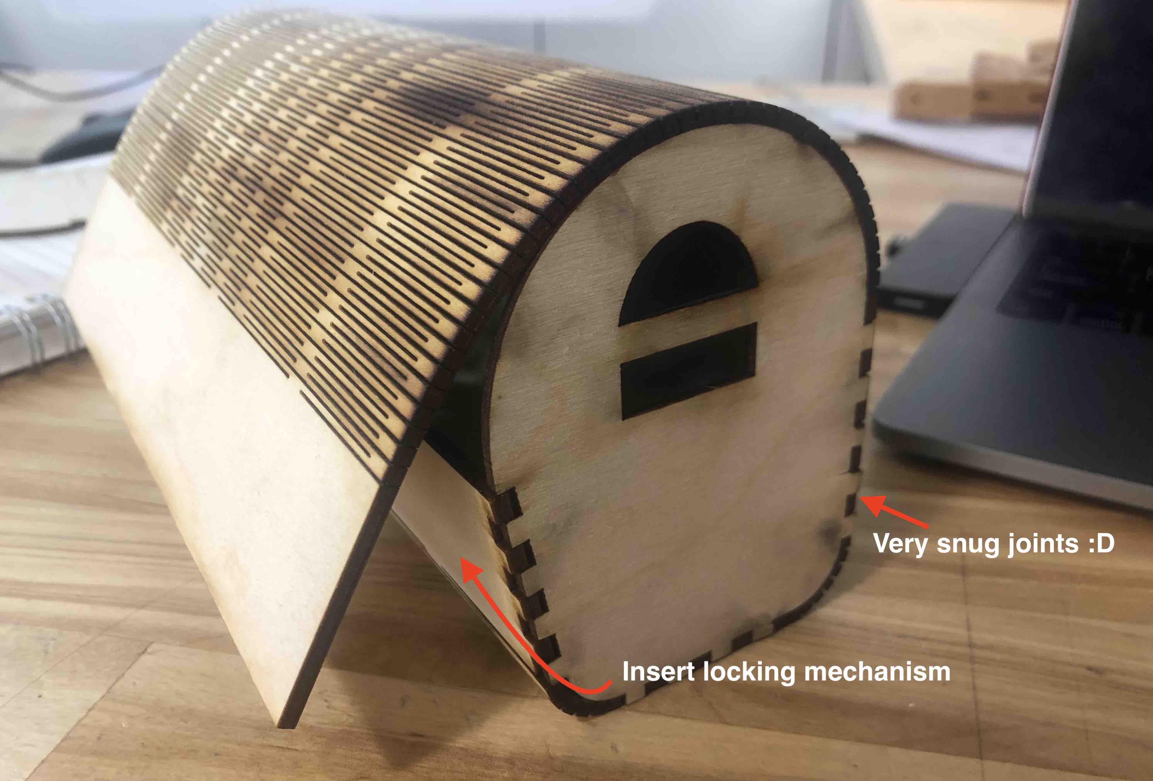
This time, it bent really beautifully.

I assembled my bag and everthing seemed fine. The finger joints did not fit as snugly so the bag did not stay together. I realised that this was because I added the kerf to the finger joint dimensions only once instead of twice. Therefore, I have to change the dimensions for my sides.
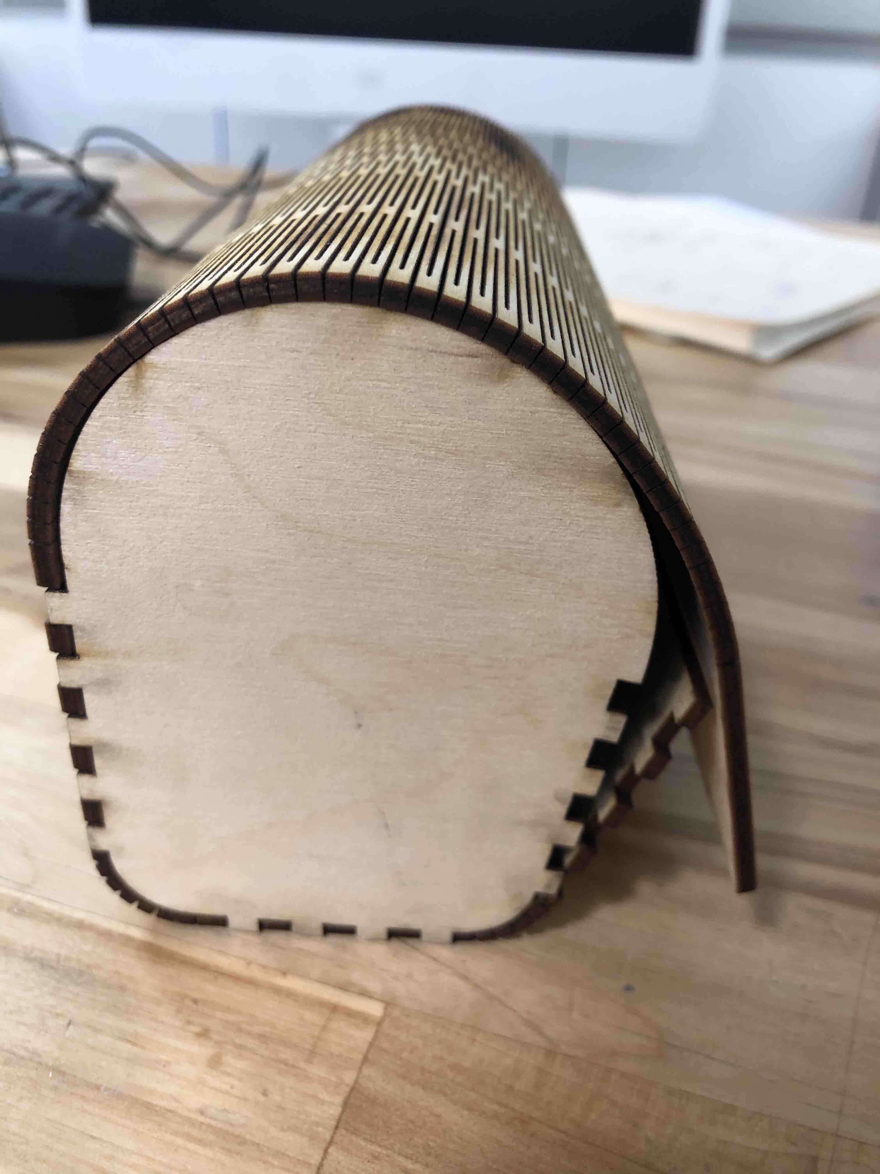
I increased the joints on the sides by about 0.2mm and it was perfect!
Group Assignment
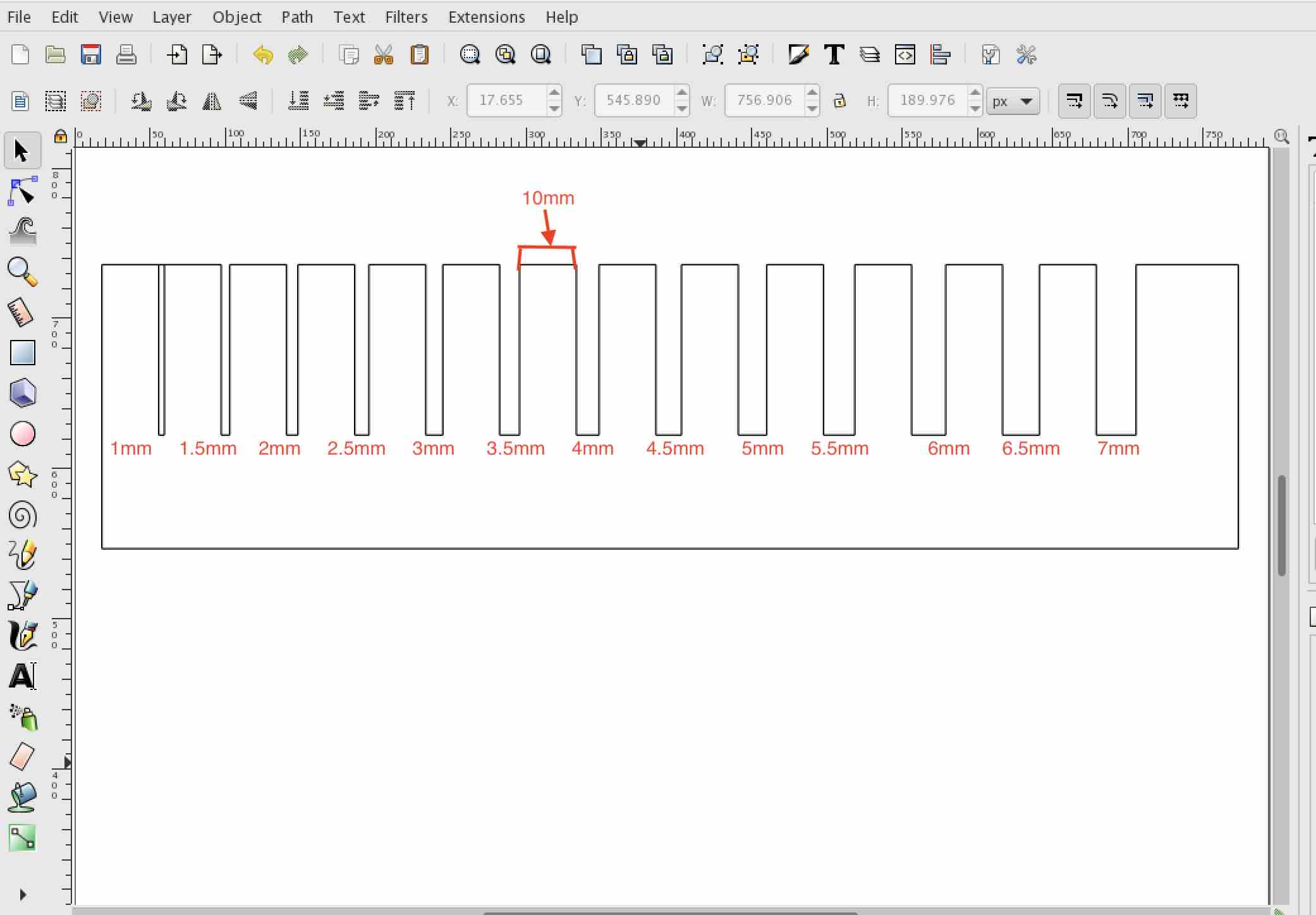
The group assignment for the week was to characterize the laser cutters focus, power, speed, rate, kerf and joint clearance. To start, I designed a shape on Fusion360 with cut outs ranging from 1mm to 7mm in thickness. Next, I exported the sketch as a dxf file and opened it up on inkscape. This file also opens on the trotec software for cutting.
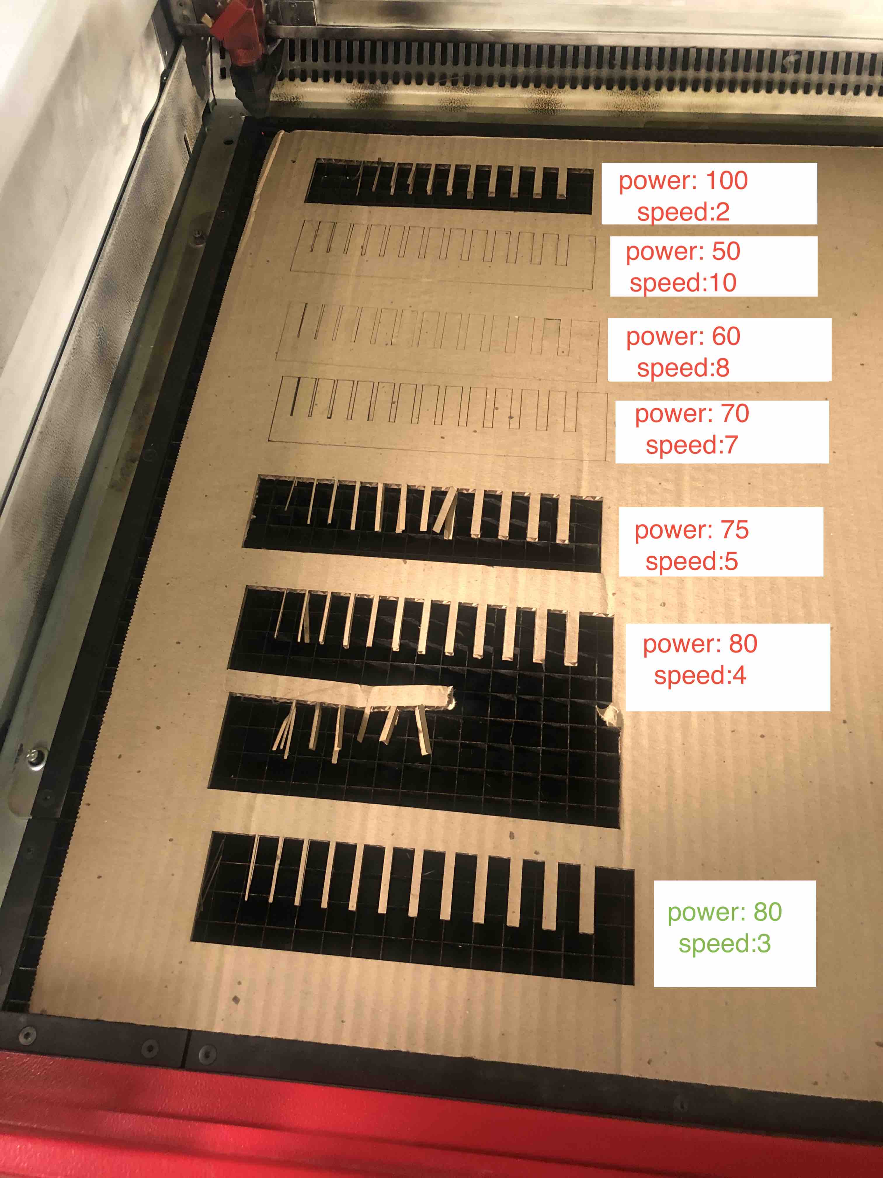
We did the first cut with the initial setting on the laser cutter and… FIRE!

So Martina and I started experimenting with different settings on the power and speed to find the perfect one for cardboards. The fire scared us so we lowered the power by quite a lot and then slowly increased it. The first few cuts did not go all the way through. We finally found the perfect power and speed so that there was no fires and also cut all the way through.
Using the cut-out pieces I figured that the 3mm cuts had the best fit since it was closest to the thickness of the material. To figure out the kerf of the laser, I measured the 10mm parts on the cutouts. Once I had the difference between the measured length and the computer length for 10 parts, I divided the difference by 2 and averaged the answer. The calculated kerf of the laser is 0.1065 mm.

2022
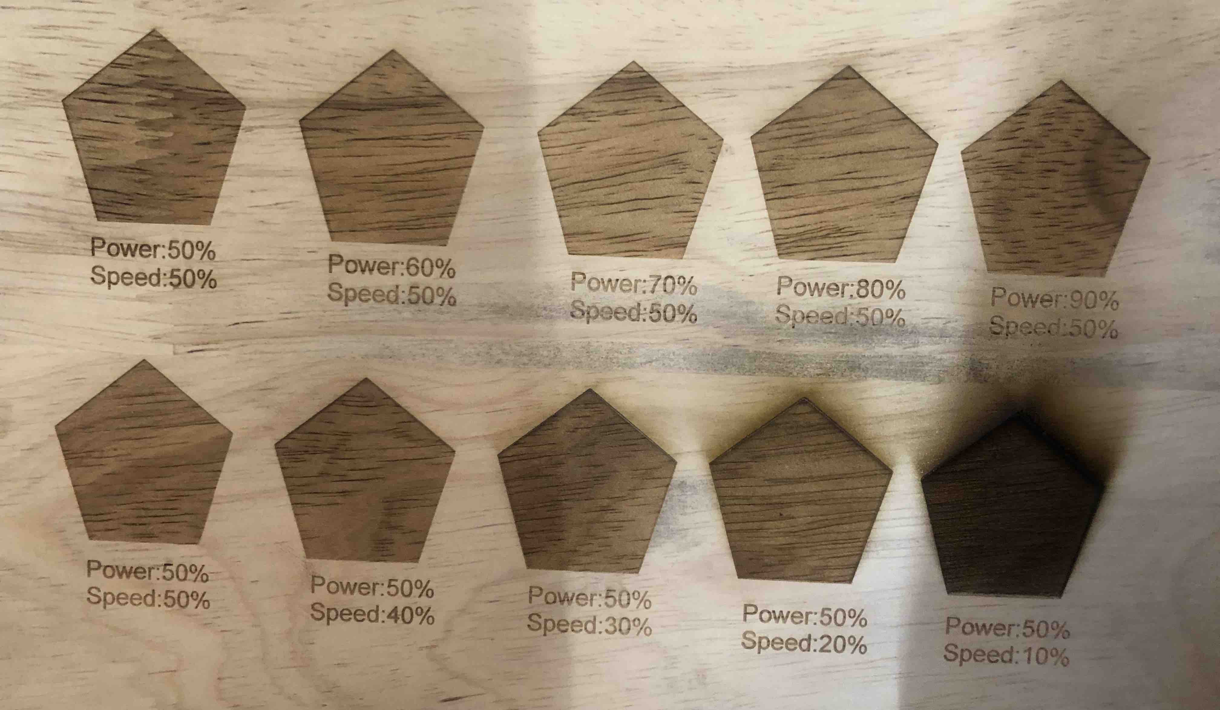
The laser cutter that we have in the Bhutan is the Epilog mini laser cutter. We tried engraving on rubber wood and cardboard by first keeping the power constant and changing the speed and then by keeping the speed constant and changing the power.
On rubberwood:
On cardboard:

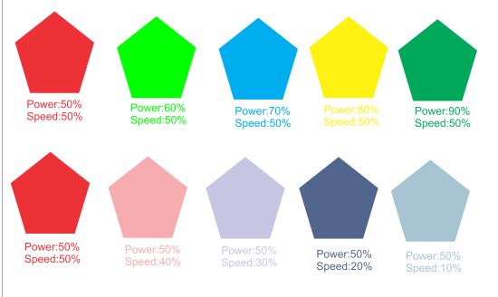
We did this by making each pentagon a different color and then matching the RGB of the color to the power and speed on the laser.
Parametric Construction Kit
The parametric construction kit is the last thing that I worked on for the week. With the vinyl cutting, figuring out how to use the laser cutter, learning to design on Fusion360, and then getting caught up in a superlong tutorial about living hinges for my final project left me with about an hour to design and cut my contruction kit. Therefore, to save time, I designed five very generic shapes with the same cut out dept (20 mm) and thickness (3 mm).
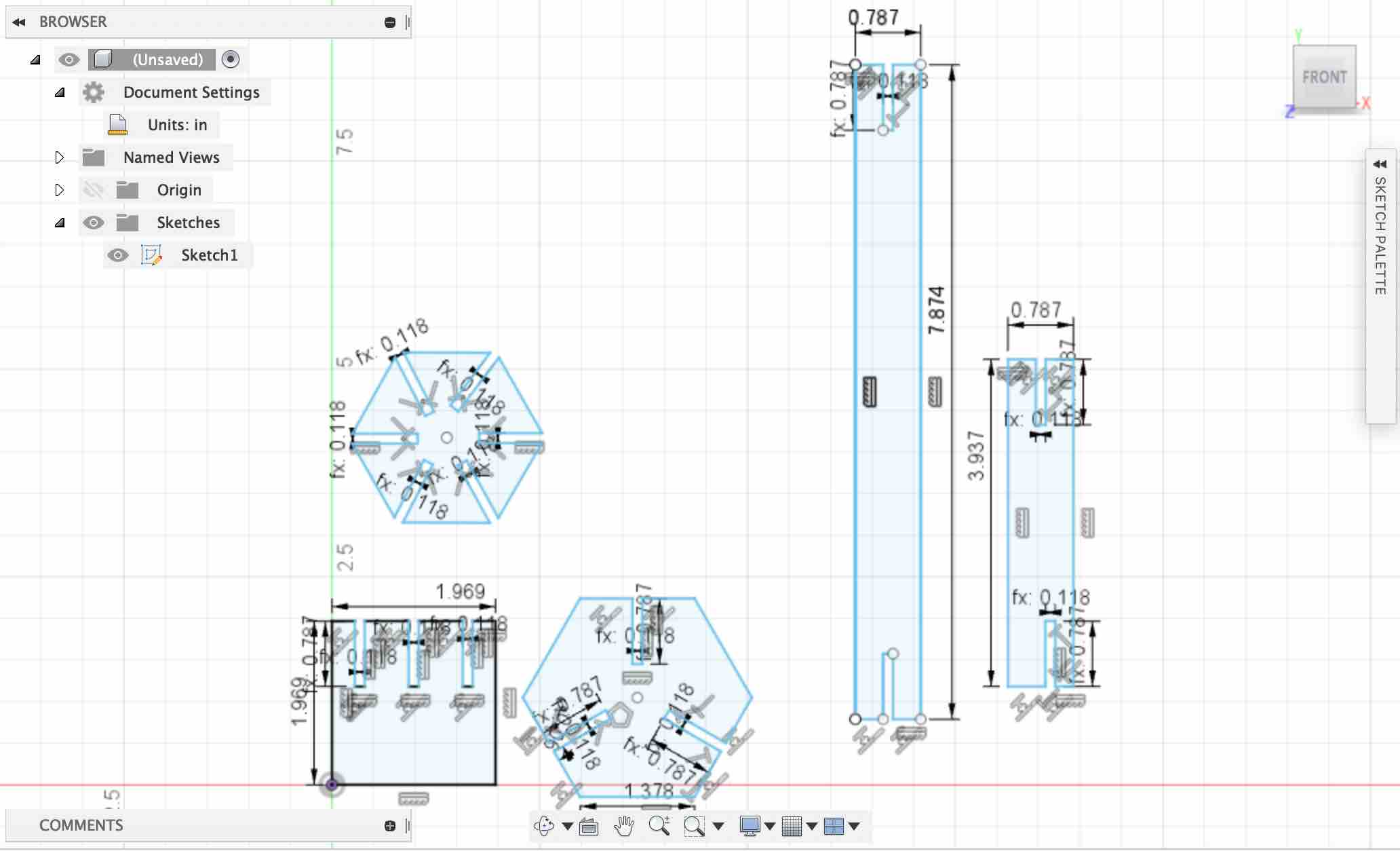
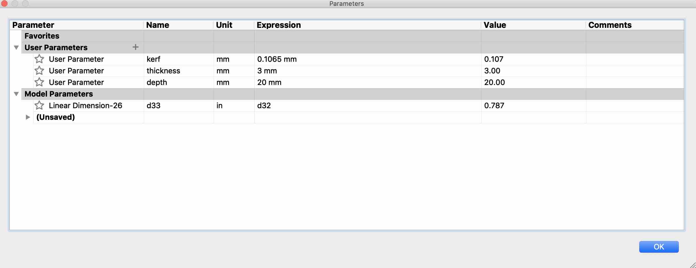
The parameters table for the sketch:
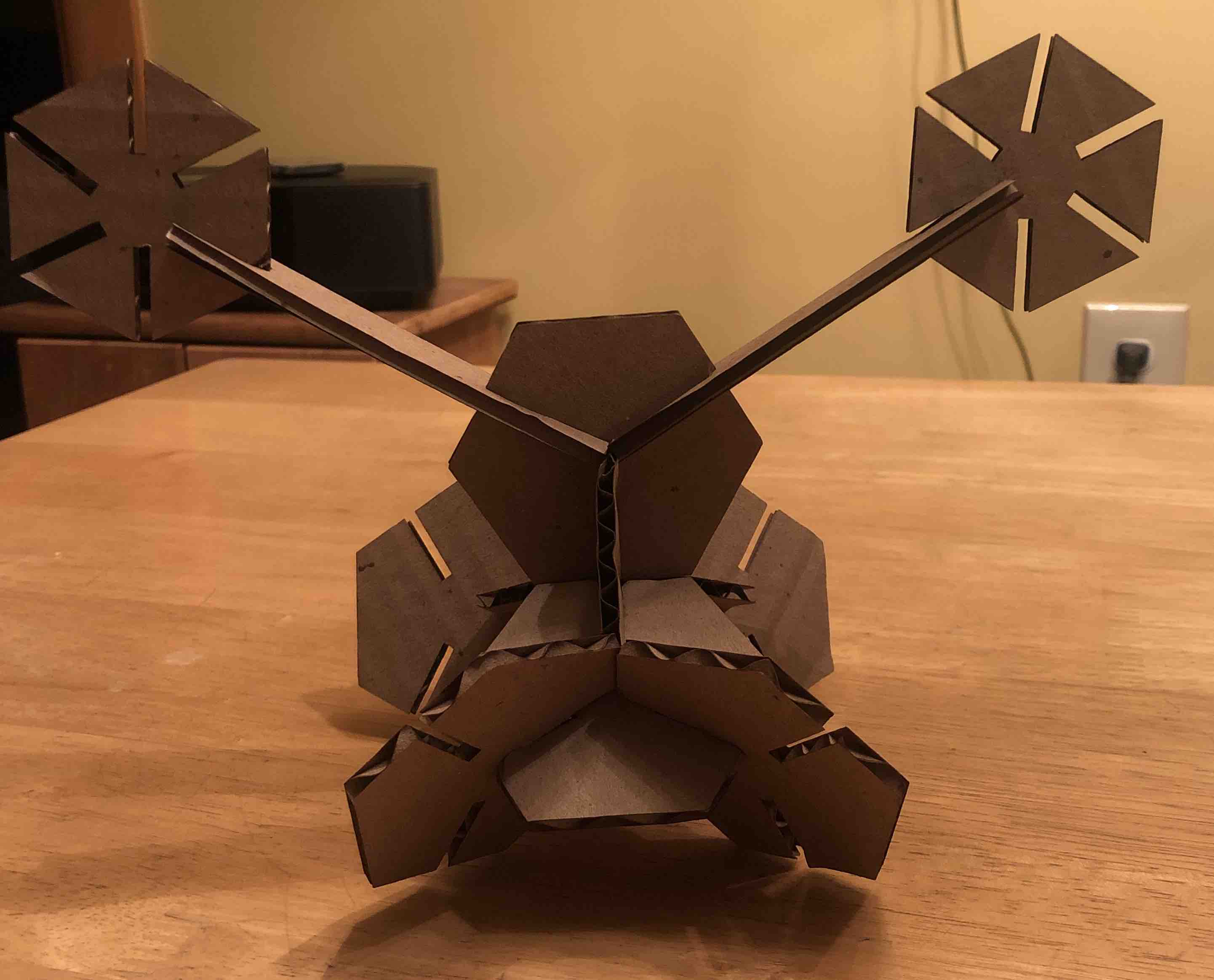
Next, I cut out each shape multiple times and hoped that they would fit together into some shape:

I ended up not using 3 of the 5 shapes. The hexagonal and octagonal cutouts fit together to make a shape. What it is will be left for the viewers imagination:

Design Files
Assessment Guide
linked to the group assignment page (Described on this page)
Explained how you parametrically designed your files
Documented how you made your press-fit kit
Documented how you made your vinyl cutting
Included your hero shots
Included your original design files