9. Input Devices
This is the second week working from home with our arduino kits. After countless youtube tutorials, I finally have a better understanding of how to work with them. It was fun to work on some small projects while in a lockdown.
This week was all about sensors. It was about how we bring the outside world into our processors. I did two projects. For the first, the input is a code on the keypad, and the output is a red LED turning off and a green one turning on. For the second project, the input is a motion sensor and the output is a buzzer sounding for a few seconds and a LED lighting up.
For a 2022 update, I worked with the fingerprint sensor that I will use in my final project. It is the GT-521FX2 Fingerprint Scanner. I decided to go with this one since it is small and compact, while highly efficient.
Group Assignment
The 2022 group assignment is linked here.
Class Notes

Keypad with LCD screen
Setup
Last week I managed to get the servo motor to respond to a code on they keypad. I wanted to add the LCD screen to the project but was unable to integrate all three. So this week I managed to integrate the keypad, LCD screen and an LED light. I followed this tutorial on youtube.
Here is the list of things required:
- Arduino Uno
- Breadboard
- 4X4 keypad
- Red and Green LED
- LCD
- 220 ohm resistors (x2)
- Wires
- Potentiometer
This is how to connect the components:
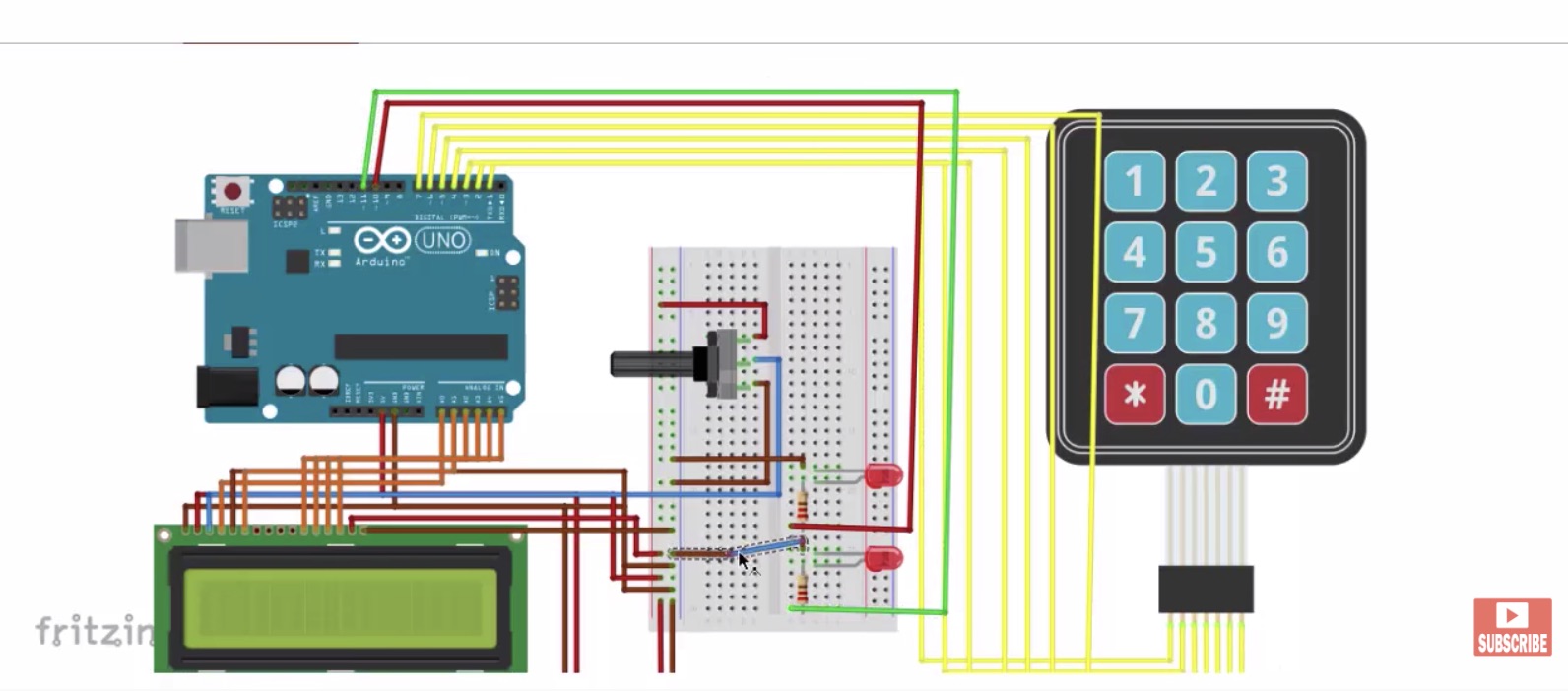 image taken from youtube tutorial
The hardest thing to understand was the connections on the keypad and the LCD. I found this image on the datasheet of the component that helped me understand it better:

This is where each pin connects:
- VSS: GND on the breadboard
- VDD: 5V on the breadboard
- V0: to the potentiometer on the breadboard
- RS: A0 on the Arduino
- RW: GND on the breadboard
- E: A1 on the Arduino
- D0-D3: not connected
- D4: A2 on the arduino
- D5: A3 on the arduino
- D6: A4 on the arduino
- D7: A5 on the arduino
- A: 5V on the breadboard
- K: GND on the breadboard
The datasheet of the keypad was also super helpful. Here is the pin configuration for the keypad:

Internal structure of the keypad:

Pins R1, R2, R3, R4, C1, C2, C3, and C4 connect to digital pins 1-8 on the arduino.
Programming
First off we need to include the LCD and keypad library in our code.
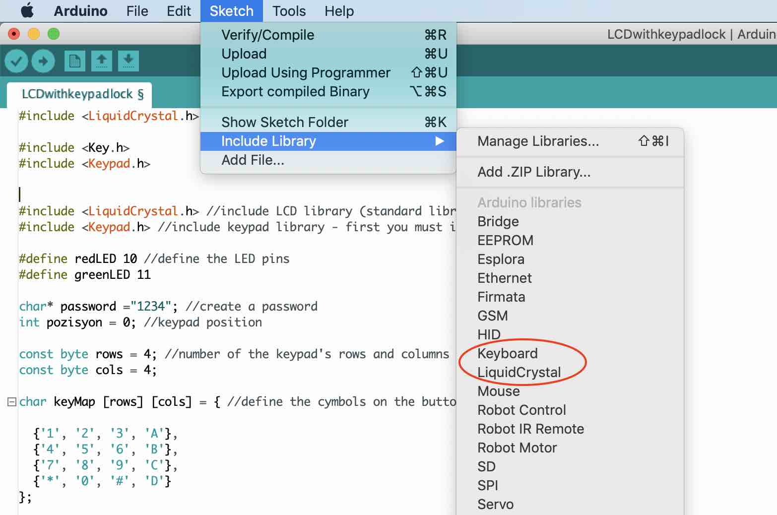
This is the code for the program. It was taken from the tutorial website here.
#include <LiquidCrystal.h> //include LCD library (standard library)
#include <Keypad.h> //include keypad library - first you must install library

#define redLED 10 //define the LED pins
#define greenLED 11

char* password ="1234"; //create a password
int pozisyon = 0; //keypad position

const byte rows = 4; //number of the keypad's rows and columns
const byte cols = 4;

char keyMap [rows] [cols] = { //define the symbols on the buttons of the keypad

  {'1', '2', '3', 'A'},
  {'4', '5', '6', 'B'},
  {'7', '8', '9', 'C'},
  {'*', '0', '#', 'D'}
};

byte rowPins [rows] = {1, 2, 3, 4}; //where the pins are connected to on the arduino
byte colPins [cols] = {5, 6, 7, 8};

Keypad myKeypad = Keypad( makeKeymap(keyMap), rowPins, colPins, rows, cols);

LiquidCrystal lcd (A0, A1, A2, A3, A4, A5); // pins of the LCD. (RS, E, D4, D5, D6, D7)

void setup(){

  lcd.begin(16, 2);
  pinMode(redLED, OUTPUT);  //set the LED as an output
  pinMode(greenLED, OUTPUT);
  setLocked (true); //state of the password
}

void loop(){

  char whichKey = myKeypad.getKey(); //define which key is pressed with getKey

  lcd.setCursor(0, 0);
  lcd.print("    Welcome");
  lcd.setCursor(0, 1);
  lcd.print(" Enter Password");

  if(whichKey == '*' || whichKey == '#' || whichKey == 'A' ||       //define invalid keys
  whichKey == 'B' || whichKey == 'C' || whichKey == 'D'){

    pozisyon=0;
    setLocked (true);
    lcd.clear();
    lcd.setCursor(0, 0);
    lcd.print("  Invalid Key!");
    delay(1000);
    lcd.clear();
  }
  if(whichKey == password [pozisyon]){

    pozisyon ++;
  }
  if(pozisyon == 4){
    setLocked (false);
    lcd.clear();
    lcd.setCursor(0, 0);
    lcd.print("*** Verified ***");
    delay(3000);
    lcd.clear();
    lcd.setCursor(0, 0);
    lcd.print("Your bag");
    lcd.setCursor(0, 1);
    lcd.print("is now open");
    delay(3000);
    lcd.clear();
  }
  delay(100);
}

void setLocked(int locked){
  if(locked){
    digitalWrite(redLED, HIGH);
    digitalWrite(greenLED, LOW);
    }
    else{
      digitalWrite(redLED, LOW);
      digitalWrite(greenLED, HIGH);
    }
  }
I changed the final message to say “Your bag is now open.” since I hope to use this towards my final project.
Here is how it works:
PIR sensor with Buzzer and LED
The second project that I decided to do is to create a motion sensor alarm. I followed this tutorial.
Components required:
- breadboard
- PIR motion sensor
- LED light
- arudino uno
- jumper wires
- buzzer
- 220 ohm resistor
The longer pin on the buzzer is the postive pin. Connect this to any of the digital pins. I connected it to pin no 12. The shorter pin is connected to ground on the breadboard.
Like the buzzer, the longer pin on the LED is the positive pin. Connect this any digital pin. I connected it to pin no 13. The shorter leg is connected to ground on the breadboard through the resistor in series.
The PIR motion sensor has 3 pins. The first pin is the ground pin. This is connected to the ground on the arduino. The middle pin is the output pin. This can be connected to either the digital or the analog pins on the arduino. I connected it to analog pin A0. The third pin is the Vcc pin that connects to the 5V pin on the arduino.
Programming
Here is the code obtained from the tutorial website:
const int motionpin=A0;
const int ledpin=13;
const int buzzpin=12; // ledpin,motionpin and buzpin are not changed throughout the process
int motionsensvalue=0;
void setup() {

Serial.begin(9600);
pinMode(ledpin, OUTPUT);
pinMode(motionpin,INPUT);
pinMode(buzzpin,OUTPUT);
}
void loop() {

motionsensvalue=analogRead(motionpin); // reads analog data from motion sensor
if (motionsensvalue>=300){
digitalWrite(ledpin,HIGH);
tone(buzzpin,150); //turns on led and buzzer
}
else {
digitalWrite(ledpin,LOW); //turns led off led and buzzer
noTone(buzzpin);
}
}
I changed the motion threshold value from 200 to 300 and experimented with the buzzpin tone. Here is how it worked:
I still have some trouble designing boards on EAGLE. What is particularly confusing is how the arduino set-up translates into a board that I can design and make. This is something I hope to be more comfortable with by next week.
2022 Fingerprint Sensor
For this week i decided to try out the finger print sensor that I had ordered for my final project. he sensor that I decided to go with is the GT-521FX2 Fingerprint Scanner.
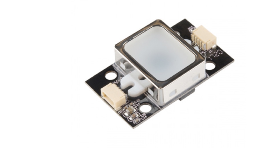
The Datasheet is linked here.
The Programming Guide is linked here
The hookup guide is linked here.
The first thing I did is refer to the hookup guide and run some example codes.
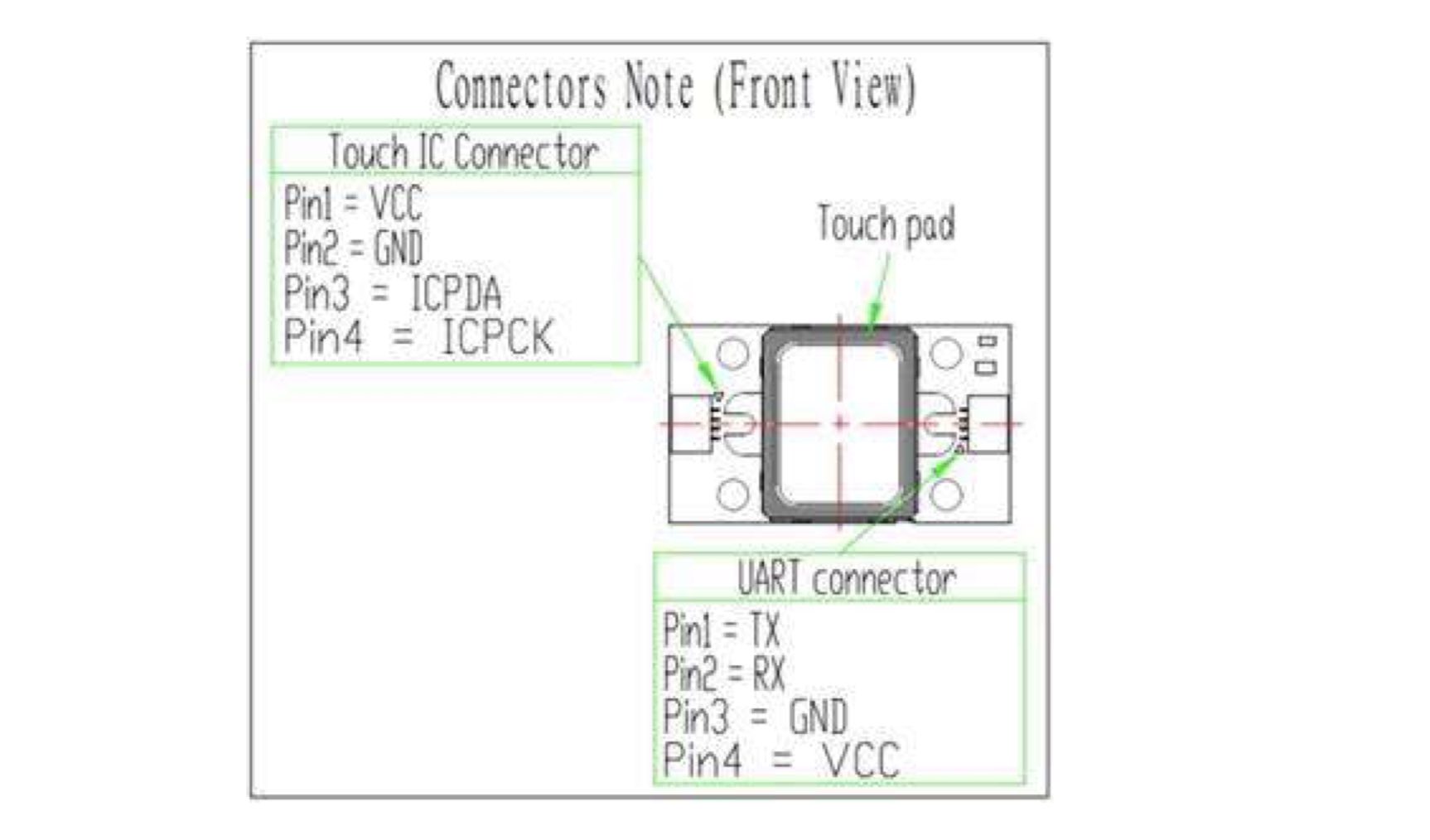
I finally realized that the product page had a hookup guide. I followed along closely. This is the a useful guide on how the pins connect:
With polarity labelled:
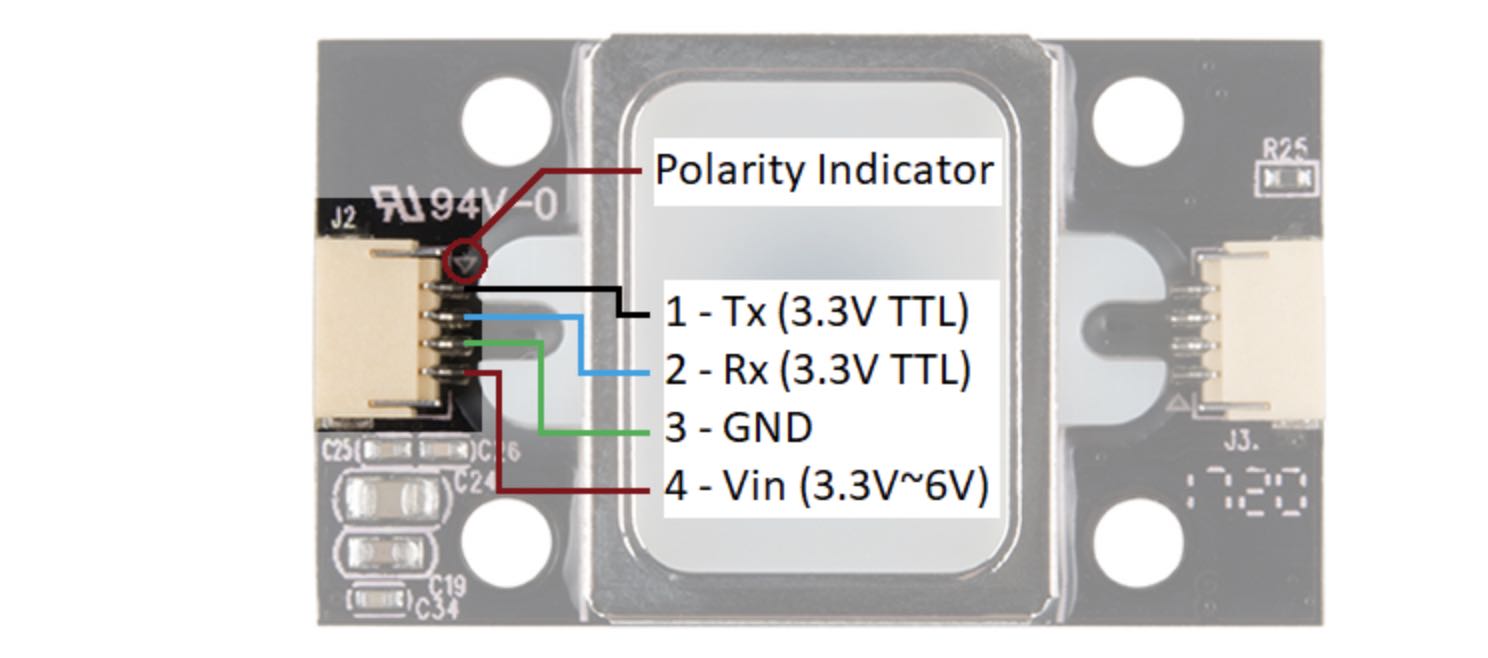
There is a marking next to the JST-SH connector that indicates polarity. The JST-SH connector breaks out the pins for serial UART and power. While the input voltage is between 3.3V and 6V, the UART’s logic level is only 3.3V. You will need a logic level converter or voltage divider to safely communicate with a 5V device.
Hardware Hookup
The hookup guide has a few options on how to hookup the sensor. I went with the second option: connecting with a 5V Arduino. Here are the things required:
- Fingerprint Scanner
- Qwiic cable
- Breadboard
- Arduino uno
- Bi-Directional Logic Level Converter or 3x 10kOhm Resistors
- Jumper wires
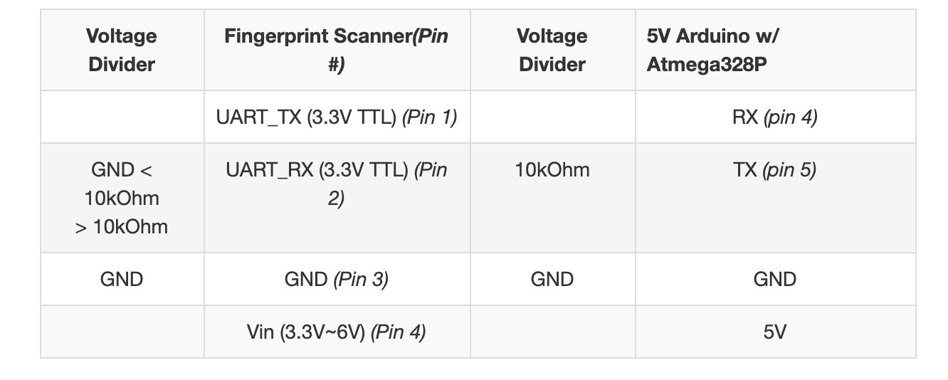
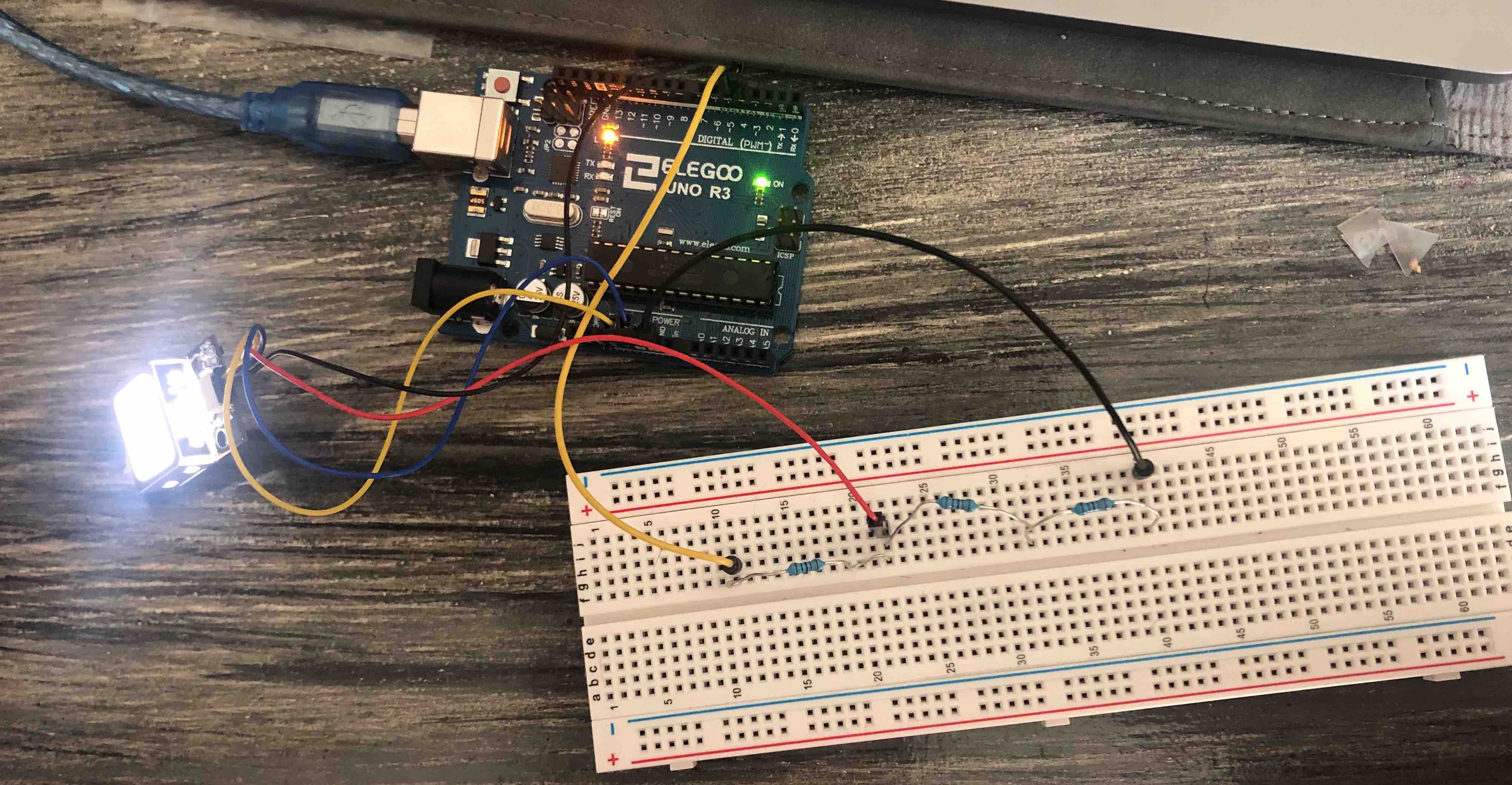
Since I don’t have a Bi-Directional Logic Level Converter, I decided to use 3x 10kOhm resistors to divide the voltage from a 5V Arduino down to 3.3V for the fingerprint scanner. This is the how I connected the wires:
This is what it looks like:
Coding
The next step in the hookup guide was to download the SDK software. The link to download is availible on the product page. I downloaded it and followed the instructions on the guide but was unable to open the app. This is probably because I am using a Mac.

I looked online on how to use the SDK software on a mac but didn’t find anything helpful. I thought I was going to be stuck here for a long time. However, I scrolled through that section on the guide and there is actually a way to replicate what the demo software does in Arduino code. Luckily there is a fingerprint scanner Arduino library written by jhawley. The code does most of the leg work for you and handles a lot of the complicated protocol commands. You can download it on the GitHub repo.
The library has three examples. Each one performs a different task with the fingerprint scanner:
- Blink the white LED.
- Enroll a fingerprint.
- Attempt to identify the fingerprint against the local database.
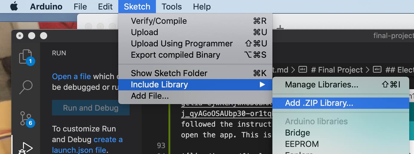
I tried the first example to make sure everything is hooked up properly. I ran the blink code from the library but it didn’t work because the FPS_GT511C3.h library was not added. I added this by going to include library and then selecting the zip folder downloaded from Gitlab.
After this was done, the rest of the process was pretty straightforward. This is the output from the blink function:
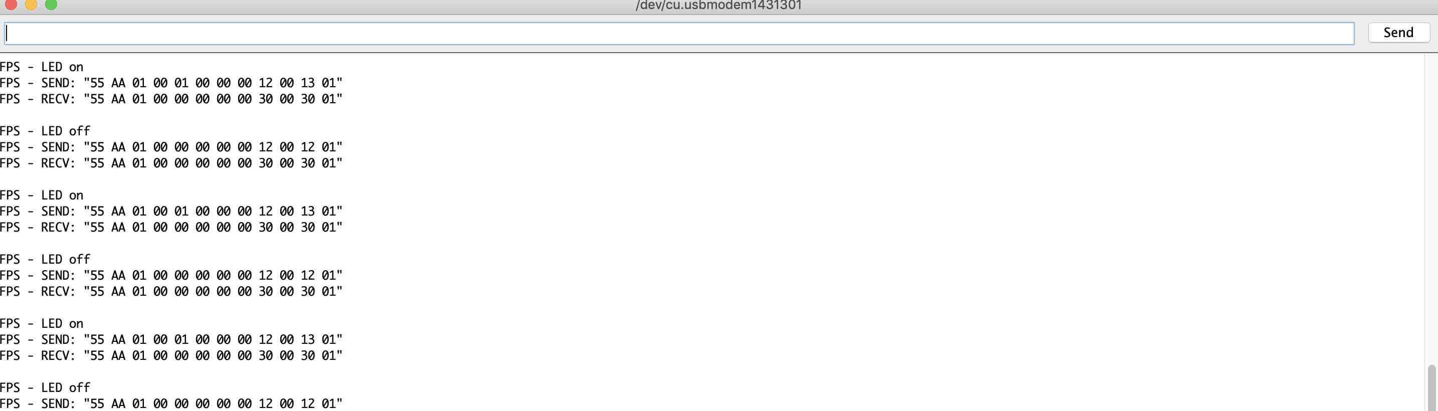
Fingerprint scanner blinking:
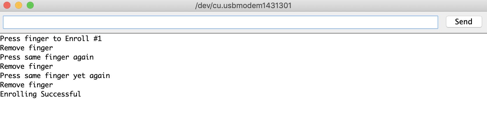
I ran the next example code, which was to enroll a fingerprint. Here is the result on the serial monitor:
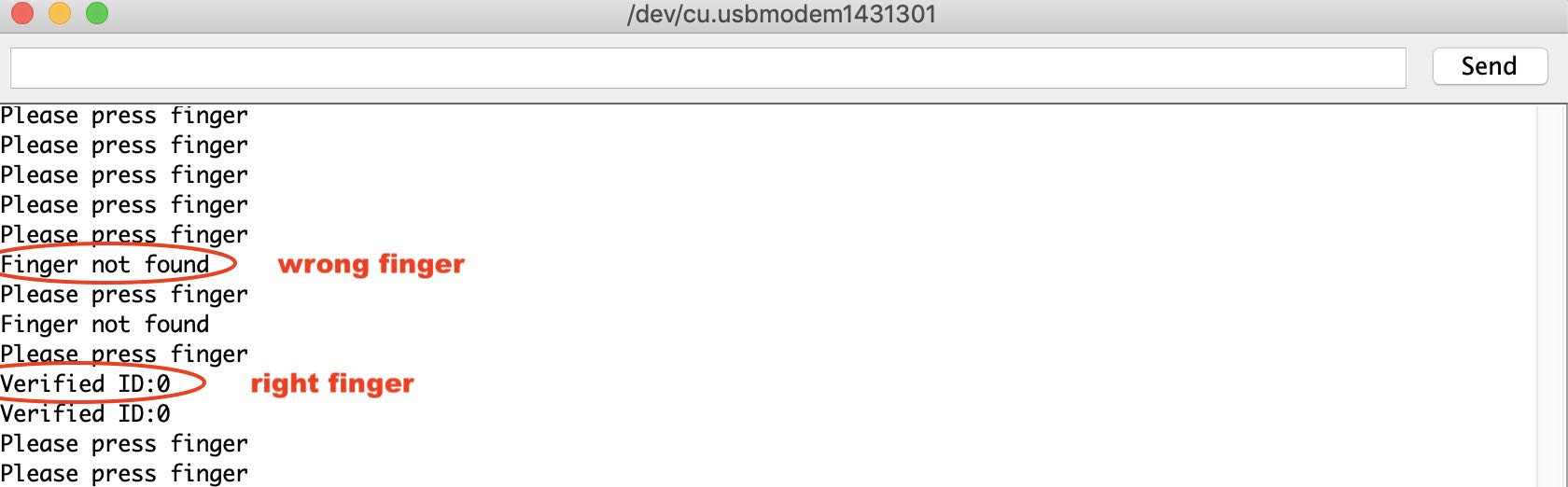
Finally, I checked the verification code. Here is the output on the serial monitor:
I had worked on combining the code for the servo and the fingerprint sensor for my final project.
Fran first said that I needed to make a diagram for my code and how i wanted it to flow. This is the chart that I drew:
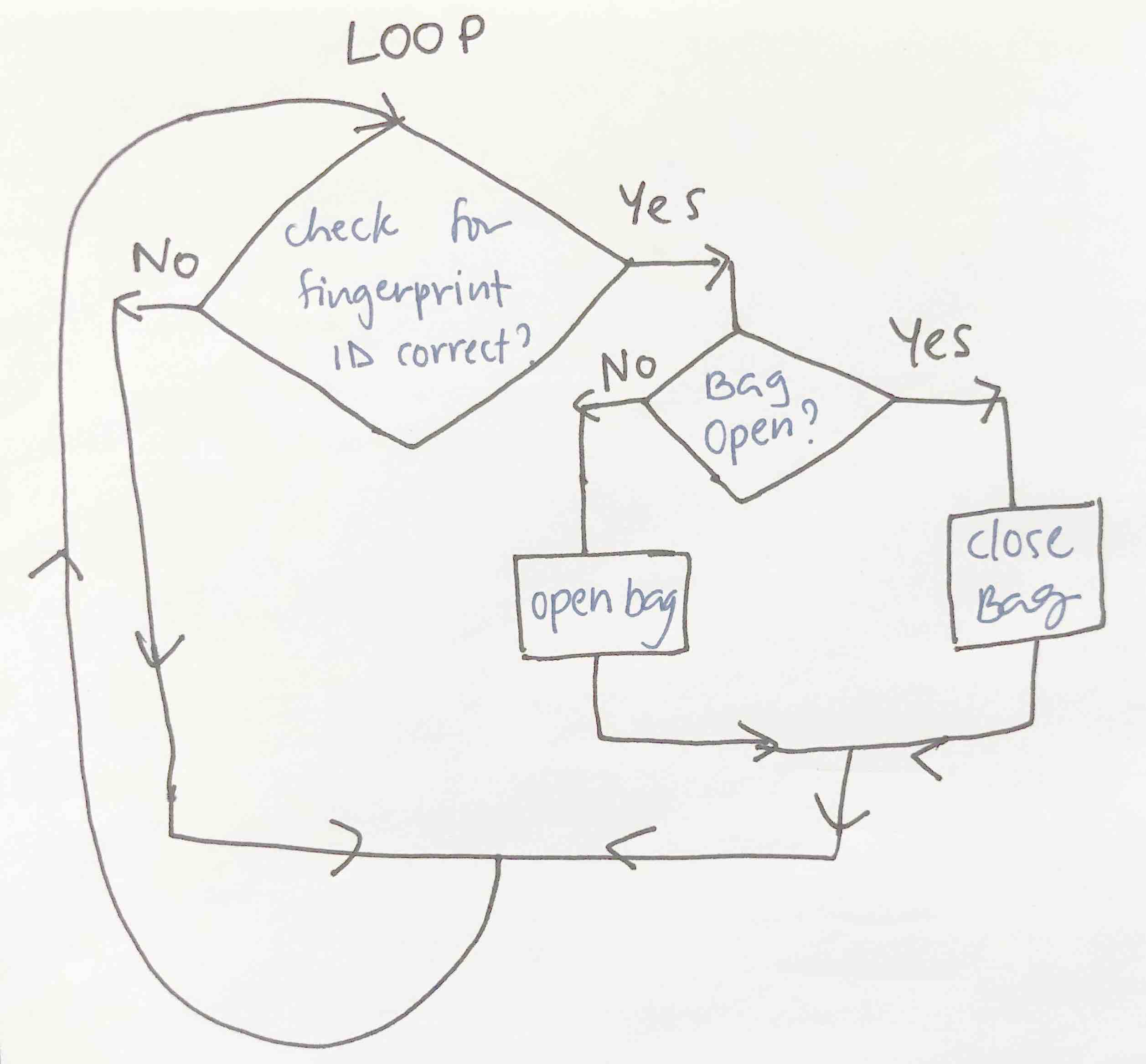
I combined the servo code and the FPS (Fingerprint sensor) code and the servo code by first opening up the FPS code (the longer more complicated one) and then adding the servo code in between one by one.
I complied the code for the servo and the FPS and finally got it to do this:
The code works well when it recognizes the fingerperint but jitters a lot when it doesnt.
Next, I deisgned a board for the Fingerprint sensor and the servo motor on KICAD.
Board Design
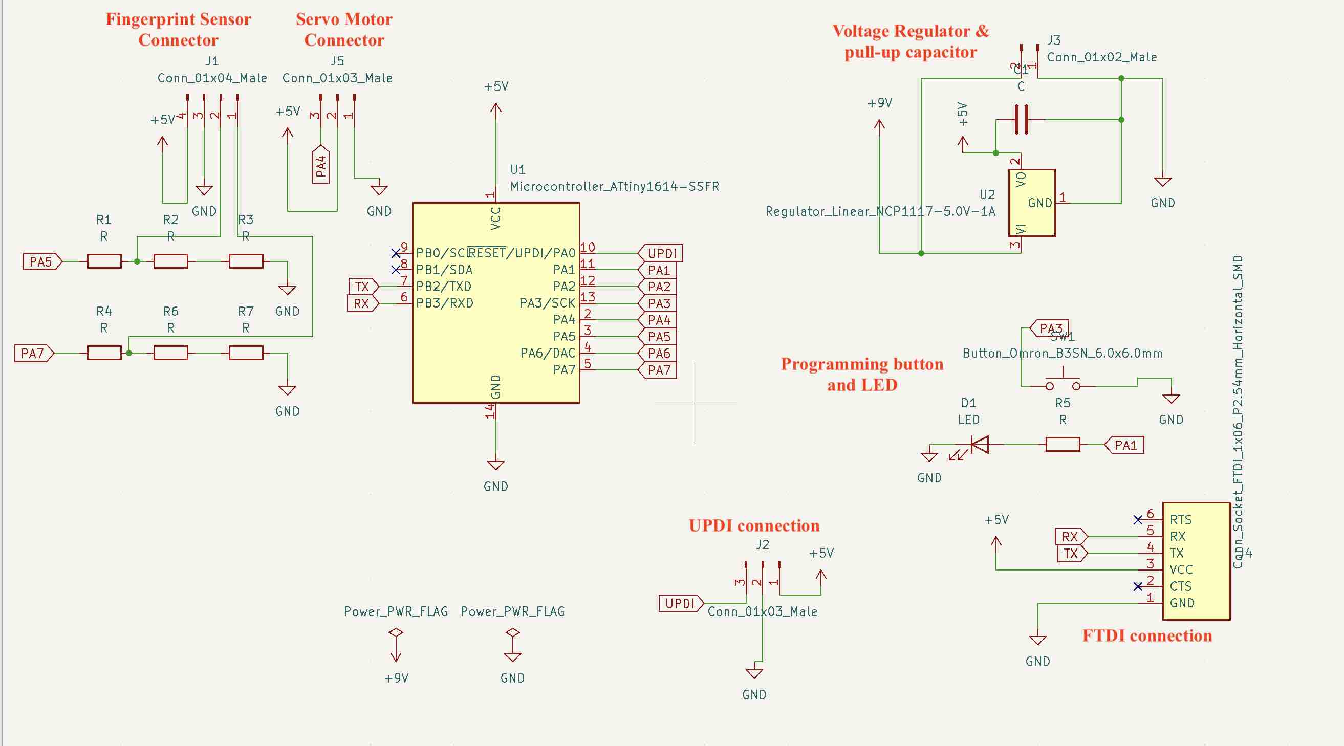
I decided to use the Attiny1614 as my microcontroller since the fingerprint library takes up quite a lot of memory. Since I will be using a 9V battery as my power supply, I also had to use a 5V 1A voltage regulator. I added 10K resistors for the RX and TX connection for the fingerprint sensor to act as a voltage regualtor since it can only take 3.3V.
This is my schematic design:
Board deisgn:

I changed the board, programmer and the port in arduino IDE and uploaded my program through the UPDI programmer. However, the fingerprint sensor did not turn on and instead got really hot. I had fried it. :( Wondering what went wrong, I showed Shuhas my board and he immediately saw the problem with it:
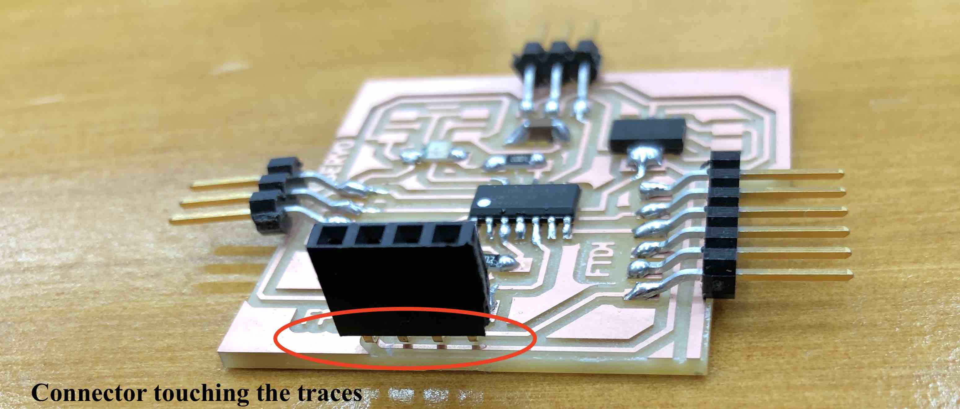
The fingerprint sensor connectors were all touching the traces underneath! I immediately ordered a new fingerprint sensor and changed the connector. I made a note to always check for shorts between VCC and GND before making connections.
This is the second board soldered and milled:
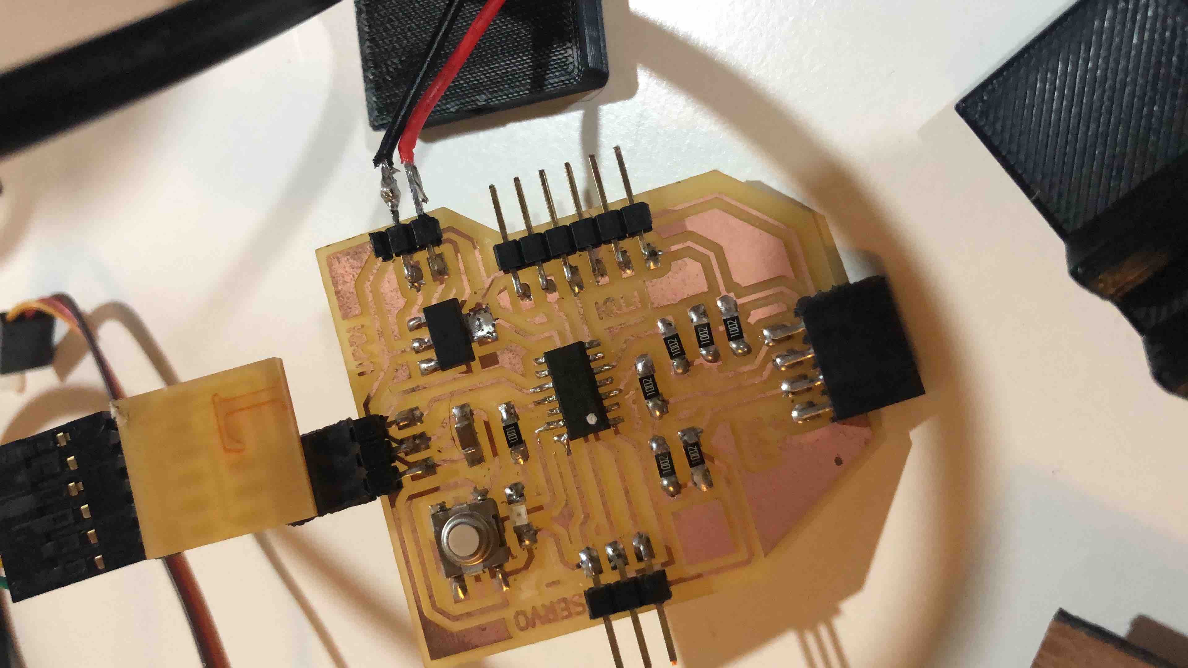
I uploaded the program through the UPDI programmer and it worked!
Download Files
Assessment Guide
Documented your design and fabrication process or linked to previous examples.
Included a ‘hero shot/video’ of your board
Linked to the group assignment page
Documented what you learned from interfacing an input device(s) to microcontroller and how the physical property relates to the measured results
Explained the programming process/es you used
Explained problems and how you fixed them
Included original design files and source code