2. Computer Aided Design
This week had a lot of things packed into it. We were asked to try our hand at multiple softwares and pick something that we were comfortable working with for each function. For a 2D design sofware I picked Inkscape and for 3D design I went with Fusion360. I used iMovie and ffmpeg for video editing and compression. For image compression, I stuck with Preview.
Vector vs Raster
There are two types of images that we work with in a fab lab; vector images and raster images. They have different purposes in design, and it is essential to understand when and where to use them This website does a good job of explaining the difference between the two.

Vector Images
Vector graphics are also known as scalable vector graphics (SVG). These graphics consist of dots connected by lines and curves. Because these graphics are not based on pixels, they are known as resolution independent, which makes them infinitely scalable. Their lines are sharp, without any loss in quality or detail, no matter what their size. Because they consist of lines and anchor points, the size of the files are relatively small.
Vectors images are mostly used in labs in machines that pass such as:
- vinyl cutters
- cutting in laser cutters
- shopbot
Raster Images
Raster images are made of pixels, or tiny dots that use color and tone to produce the image. These images are created by digital cameras, by scanning images into a computer or with raster-based software. Each image can only contain a fixed number of pixels; the amount of pixels determines the quality of the image. This is known as resolution. It is measured in dots per inch (DPI).
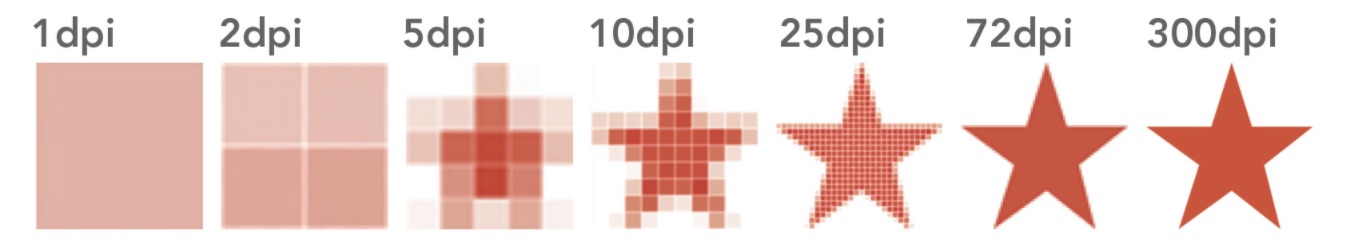
More pixels results in better quality at the same or larger sizes of the original, but this also increases the size of the file and the amount of space it takes to store the file. The lower the number of pixels, the lower the resolution.
Raster images are mostly used for:
- making 3D images
- laser engraving
- printing
Video Compression and Editing
For a video editing software, I chose imovie since it is very user friendly. For a video compression software, I decided to go with ffmpeg based on reviews online and recommendations from colleagues. After a series of failed tries using written tutorials, I realized that the best way I learn is through youtube tutorials where the tutor does it with me so I can make sure that I am going the right direction. The tutorial I used to download ffmpeg is here.
The first thing the tutorial had me do is download Homebrew. I thought I had already downloaded it after the first class but I guess it got deleted somewhere down the line so I downloaded it once again.
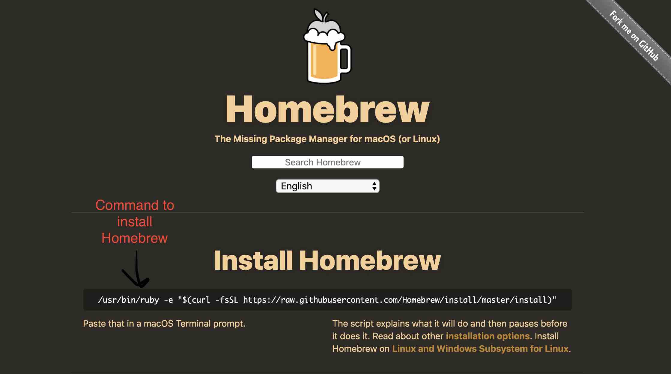
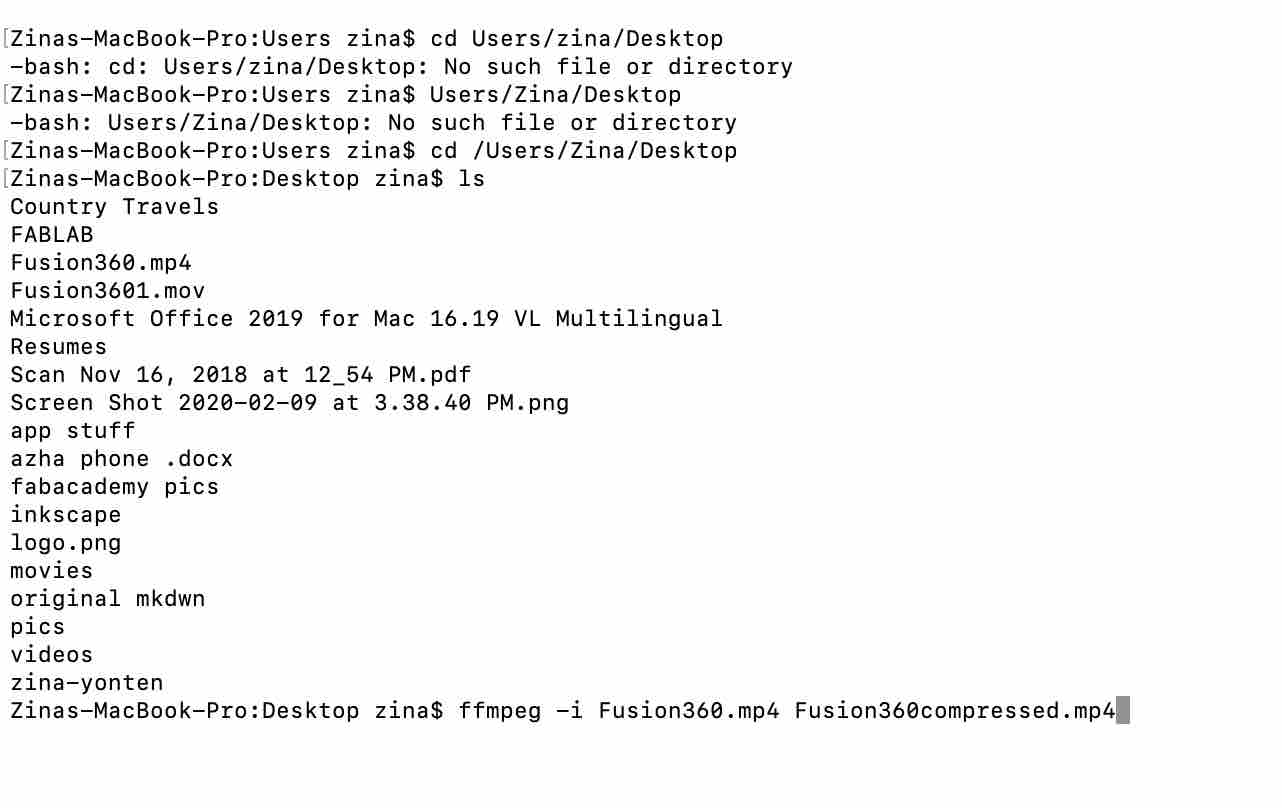
To download it, all I had to do was run the command given on their website (picture shown above) in my terminal. Once the command finished running, I made sure that Homebrew was indeed installed.

As you can see, the status says installation successful. Next, I ran a command on my terminal to download ffmpeg with Homebrew. Here is the command that I ran:

To check that it was working I looked at another tutorial to compress a video since I knew that I would have to run it at some point. After finishing up Fusion360 for the week, I did indeed have a video to compress. This is the command that I ran:
It did compress the video down to 1MB. The compressed video can be viewed by scrolling down to the 3D Design section.
I found that this website is also really great for compressing videos. I found that using ffmpeg compresses my video from about 20 MB to 4 MB. When I try compressing the same video again, it compresses it to only 3.8 MB. Therefore, i found that first using ffmpeg and then using the website is a good tactic.
2D Design
Inkscape
For a 2D design software I decided to go with Inkscape (fpr vector images) since it was free and compatible with macs. I also thought it might be the best for future classes with laser-cutting. It was tricky to download it since I also had to download Xquartz. I’m still trying to grasp my head around the whole download one app so the other can work part. To start off, I attempted a couple of youtube tutorials. Here are my tutorial takeaways:
Tutorial 1 takeaway:
- Press down scroll wheel to go up and down the page
- Command key + scroll in and out will zoom in and out
- Command key + arrow key pans around as well
- Create a shape from the vertical toolbar on the left
- After shape is created, the properties you can edit show up on top
- Can change the units from the options on top
- Can put the shape outside the page border but it will not print
- Left click on shape to edit it. Esc or click on white space to deselect it
- Left click on shape changes how you can change the shape. Eg: left click once and you can change the size. Left click again and you can skew the shape
- Plus sign in the middle of the shape determines the axis of rotation (can be outside the shape as well)
- Inside shape color is called the fill color, outside border color is called the stroke color
- To change fill color, select shape and then select the color
- To change the stroke color (border color), select shape, hold down shift key and then select the color
- .svg opens in inkscapes. To export as an image, convert to png (can convert the entire page, or a single selection)
Tutorial 2 takeaway:
- When you first draw a rectangle, there are two white squares and two white circles at the corners. Squares control the size and circles control the roundness of the corners.
- Can get to this option by double clicking quickly
- The white circles on a circle creates a partial circle.
- To bring a shape or image forward: raise up a level
- Star shape: outer white square controls size, inner white square controls the shape
- Change a star to a triangle by changing the no of corners from 5 to 3
- Spiral: option to change the number of rotations
- Erase: freehand, messy
Tutorial 3 takeaway:
- Inkscape remembers the last setting you had for each shape
- How to get to fill and stroke panel:
- Object → fill and stroke
- shift +control+f
- Right click shape → fill and stroke
- Color option:
- RBG: Red, Blue, Green. Mix these colors to get the desired color. Ideal for web use
- CMYK: Usually for printers
- Wheel: ideal for web or displays
- Stroke paint tab to change stroke colors
- Stroke style tab to change width of stroke and style
- Delete stroke by hitting the X key on stroke paint tab
- Color gradient: change the direction and color
- Different patterns possible
- Blur and opacity
Tutorial 4 takeaway:
- Ctrl+d duplicates the object directly on top of it. (copy and paste works too)
- To join shapes: select shapes, go to objects, select group (or press ctrl+g)
- Double click on a single object within a group to change only that object
- To trace image:
- Copy and paste image on Inkscape
- Path → trace bitmap
There was a total of 48 tutorials so I decided to stop here and start trying to create something on Inkscape.
Creating a logo
With all the lessons on shapes, I thought about creating a logo for my final project. This isn’t the final logo and I just created it to try my hand at Inkscape.
Here is how I was working Inkscape with different images, shapes and colors:
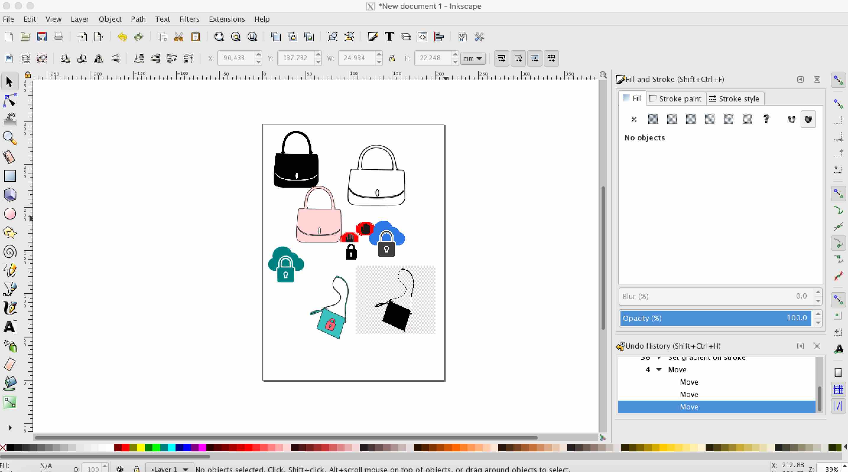
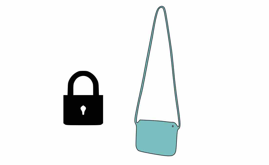
The first thing I did is take a silouette picture of a sling bag from google and paste it on a new project in Inkscape. Next, to convert it to a vector image, right click on the image and click “Trace Bitmap.”

This creates a vector image directly on top of the raster image.

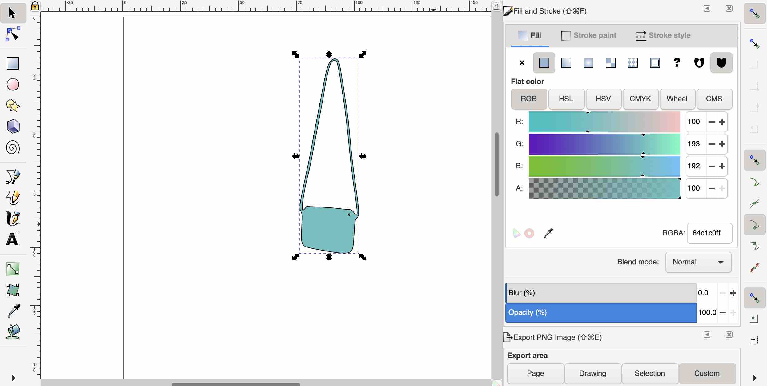
I deleted the raster image and continued editing the vector image. I changed the fill color and stroke width.
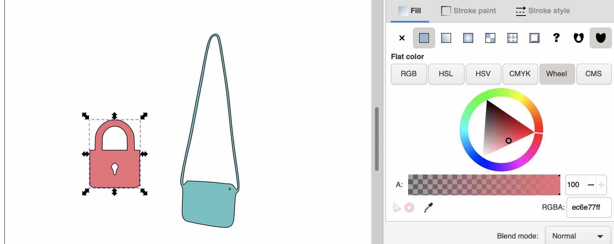
Next, I got a picture of a lock from google and pasted it. I followed the same procedure for converting it into a vector image.
Next I changed the fill color of the bag.
Next, I positioned it on the desired place. Then I drew a circle with no fill and put the logo inside it. To make everything one entity, I selected the three parts and grouped it by right clicking and selecting “group.”

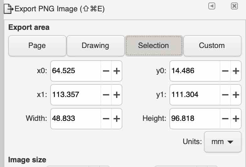
Finally, I exported the image as a selection.
Inkscape took some getting used to but it was easy to use once you get the hang of it. MY favorite part about it is how easily you can convert a raster image to vector and then export it as an svg file that you can use in Fusion360. It was much more straightforward compared to other editing softwares.
Preview
I used Preview as a raster image editing software. It comes pre installed in macs and is really simple to use. To open an image, we have to open the application from finder or just double click on an image and it automatically opens up in preview. Once the image opens, you need to click on the pencil icon to open up the editing menu. The menu has options to add shapes and texts as well as to edit the various contrast, and sharpness.

3D Design
For the two 3D design softwares I tried Fusion360 and TinkerCAD.
Fusion360
Although I would have preferred to use SolidWorks for a 3D design software since I have prior experience with it, I decided to learn and work with Fusion360 for this course since SolidWorks isn’t compatible with macs. Also, they offer a free version for hobbyists.
I didn’t have to do very detailed tutorials for Fusion360 since I am pretty comfortable with 3D design. I did attempt this tutorial and created the assembly on Fusion360 just to get a feel of the software.The user interface for Fusion360 was very similar to that of SolidWorks so I picked things up pretty fast. Something I thought that was cool with Fusion360 is the history bar at the bottom of the page. Showing my work and process got so much easier. I screen recorded the model that I made from the tutorial and put it here:

I views this tutorial to figure out how to embed a video on gitlab.
I later realised that the above video works on preview but not on my website. Therefore, I uploaded the video on youtube and embedded it here:
Having no experience with coding, I thought that simply removing the link of the youtube code from the previously embedded video and pasting the link of my youtube video in its place would embed the video. That did not work. I was super comfused as to why. I figured out that each youtube video has its own embed link that is different from the website link. I was finally able to embed my video.

Designing the model on Fusion 360
Fusion 360 is pretty straightforward and easy to use. On the left of the screen when you open it up is where your previous work gets saved. You can save your work in multiple projects and insert models from one design into the other. The top of the interface has a panel where with tools to create different types of solid bodies (solid, surface, mesh etc.)
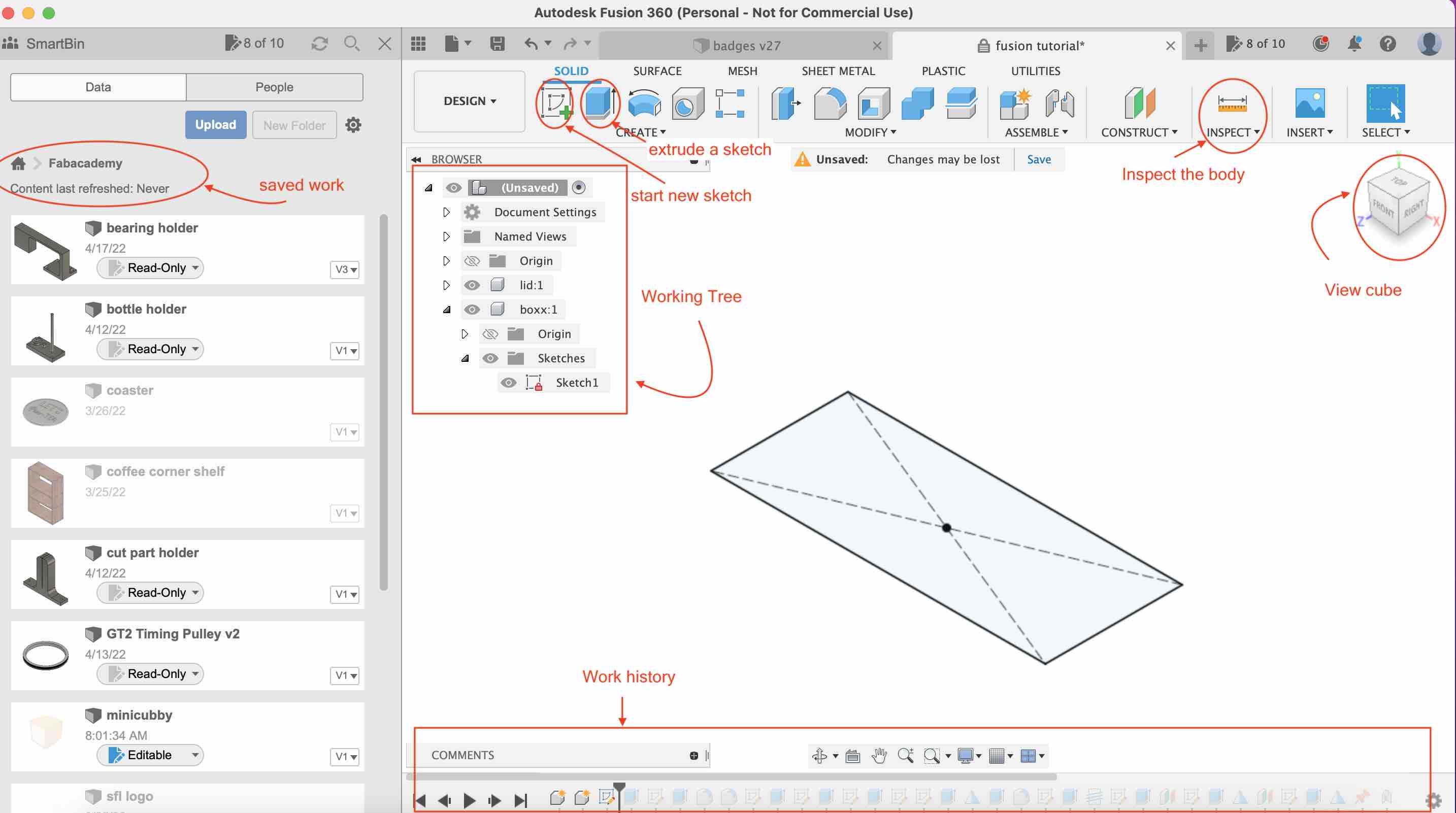
Under the create tab, there are mutiple options to create your design (revolve, loft, hole, thread…). The view cube allows you to view your model from different angles. The work tree on the left lists the sketches, bodies and components in the deisgn. The work history on the botttom records the history of how the model was made.
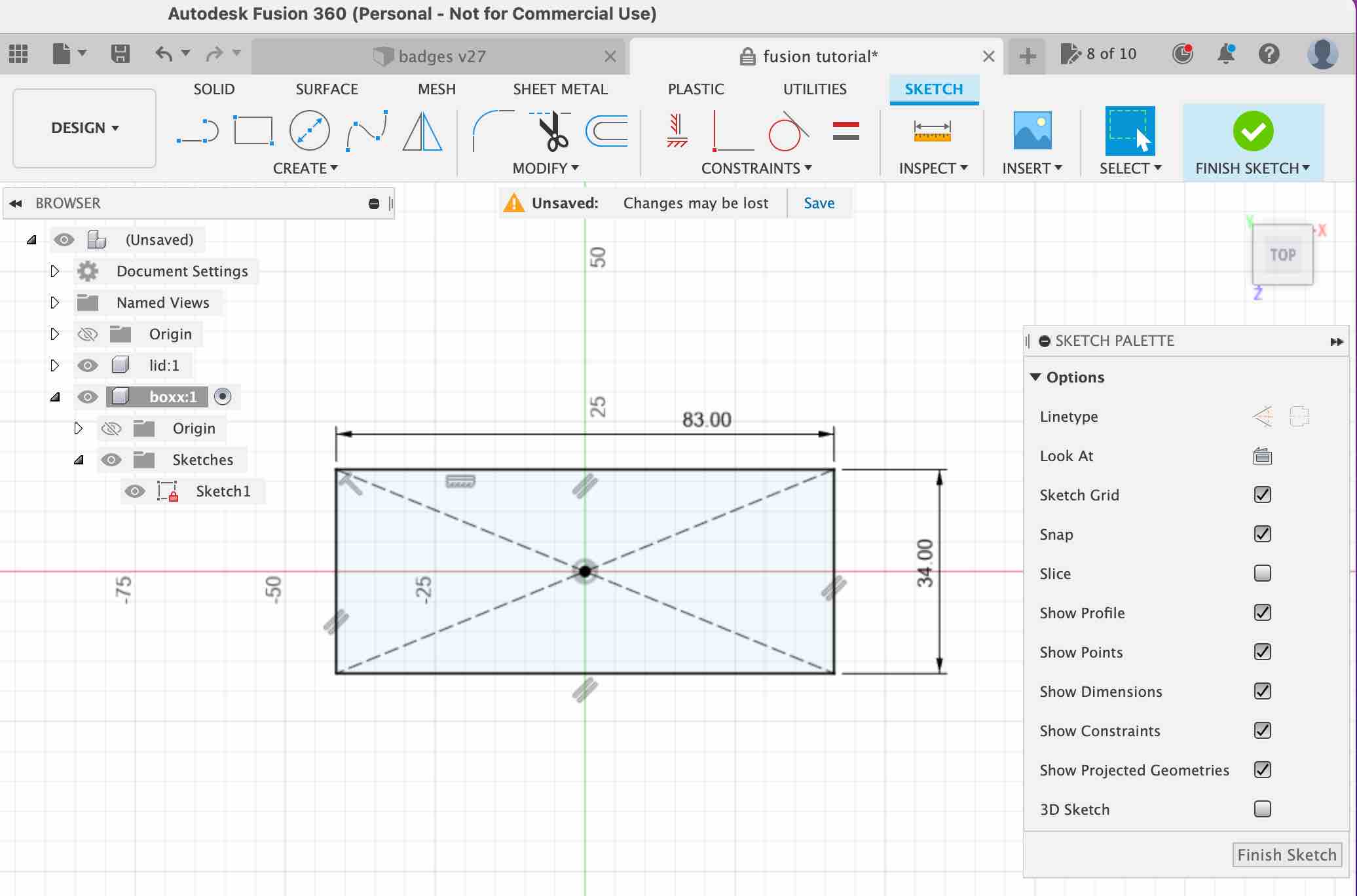
To make the test model from the tutorial, the first thing I did was start with a 2D sketch. I clicked on the center point rectangle option and choose the origin as the center. I gave it a dimension of 83mm by 34 mm and then finished the sketch
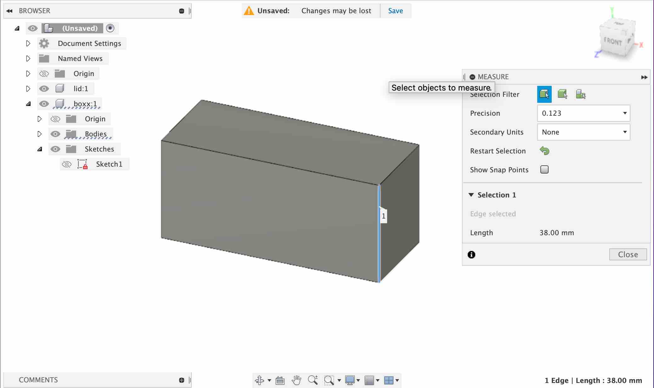
Next, to create a 3D body from the sketch, I clicked on the extrude button. I chose the rectangle as the object and extruded it by 38mm.
Next, I started a sketch on the top face of the rectangle and then cut the rectangle down by a depth of 34mm.

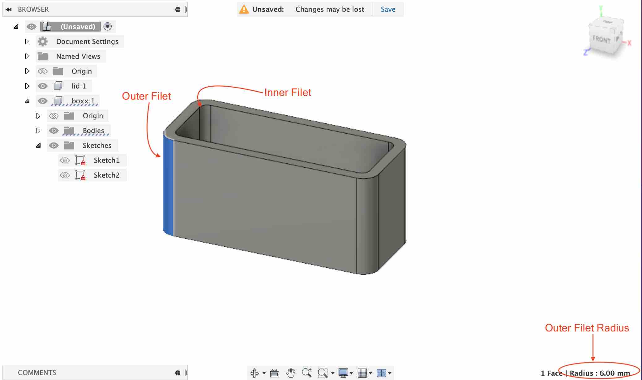
Next, I added a filet to both the inner and outer surfaces of the design.
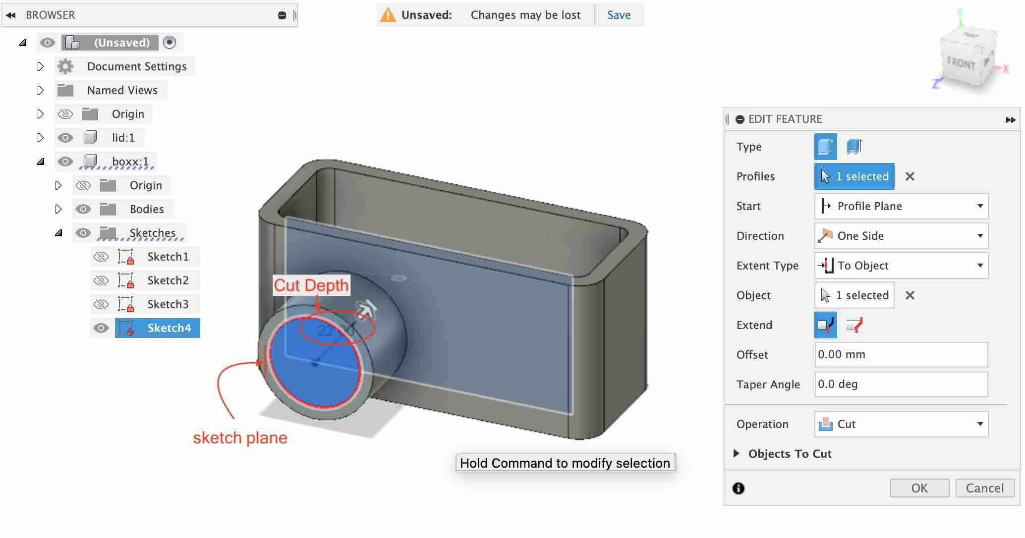
Next, I made a sketch on the front part of the model and drew a circle which I then extruded by 18mm.

Next, I drew a sketch on the front face of the cylinder and then cut it by 22mm. This means that it cuts through the cylinder to the inside of the hollow rectangle.
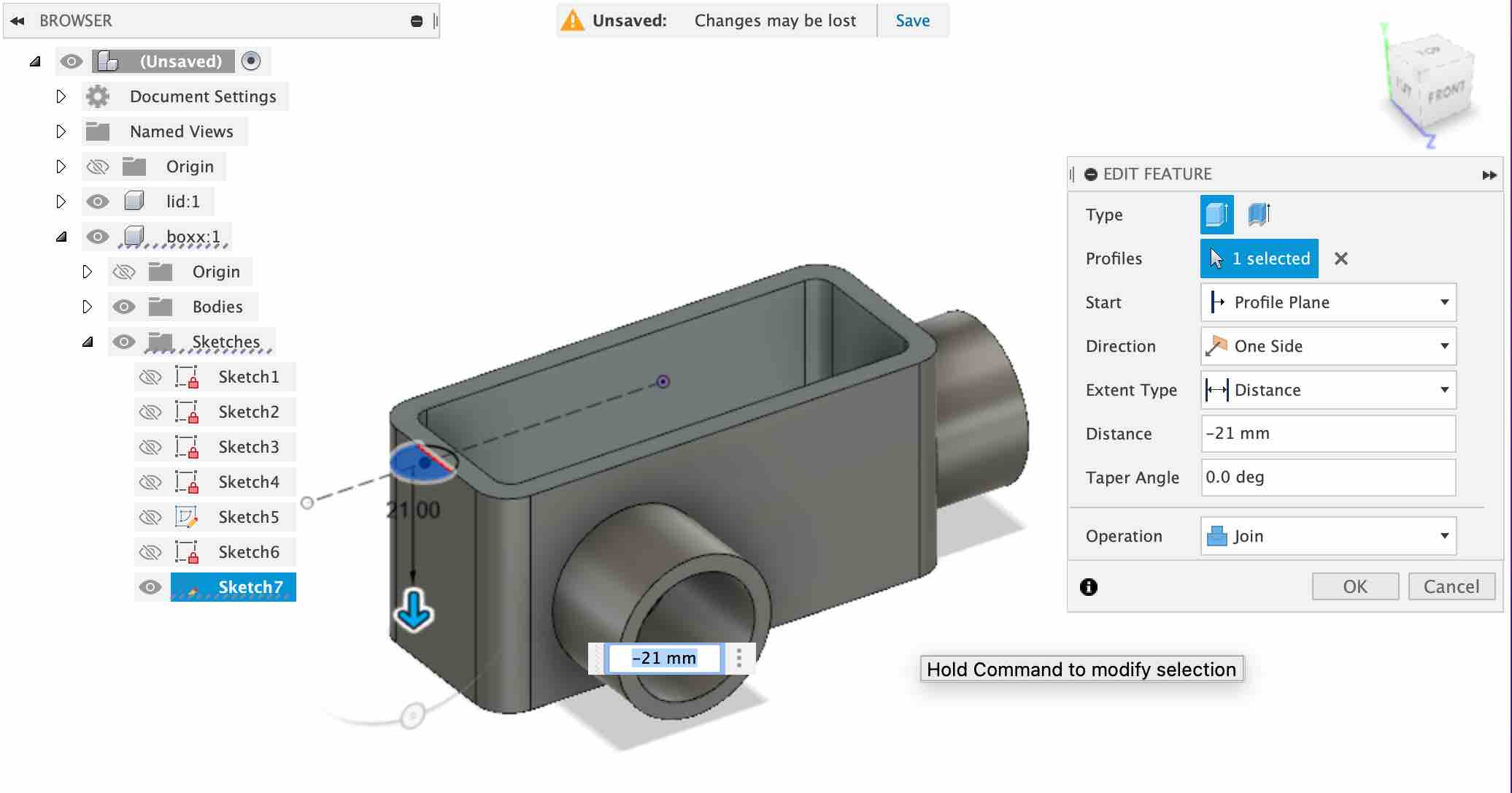
Next, I made a sketch om the side profile and did a two sided extrusion as shown in the picture below:

I continued by making an extrusion from the top profile for the holes later.
The extrusion was mirrored across the YZ plane.

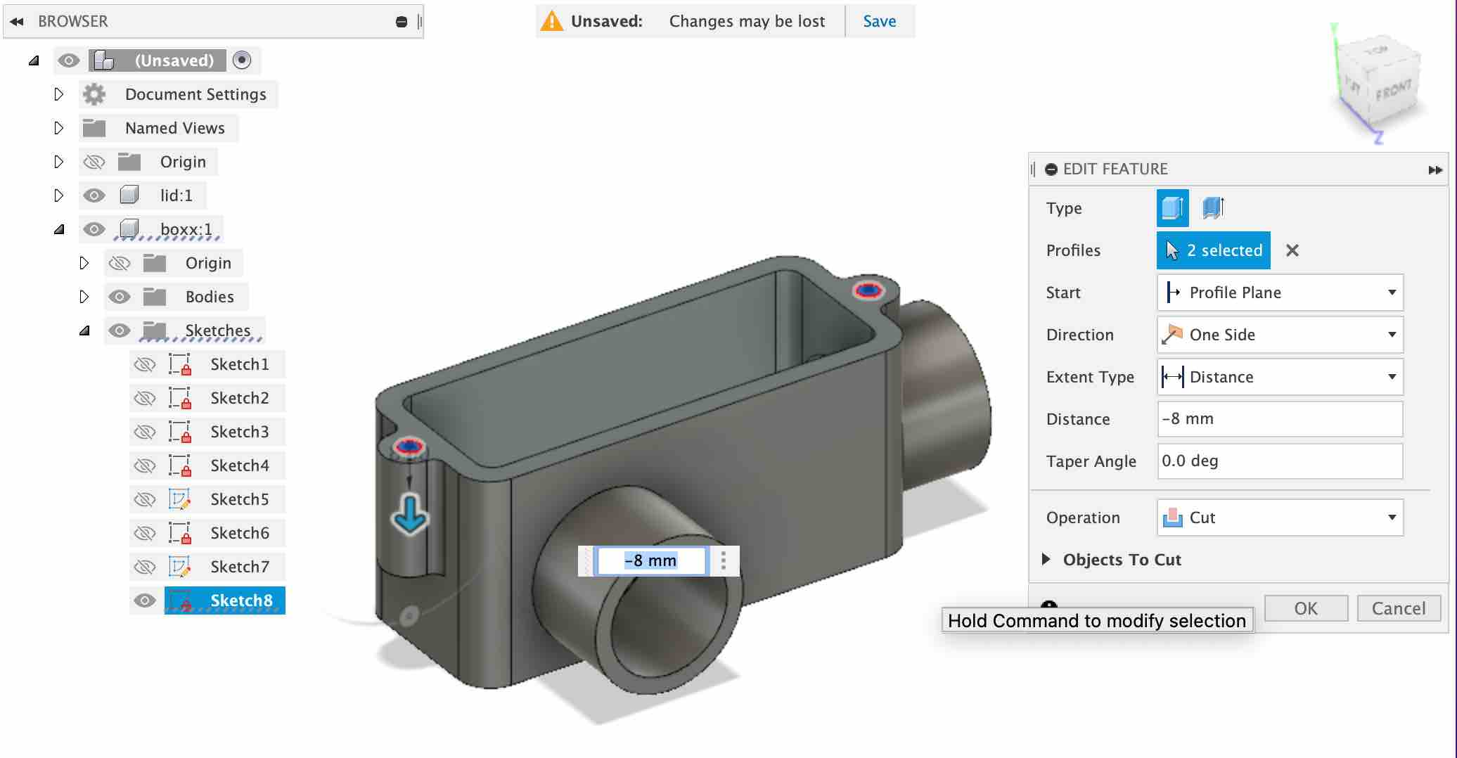
I sketched a circle on the extrusions and cut down to a depth of 8mm.
M4 size threads were added in the holes. This can be done by choosing the thread function under the create tab and putting in the desired measurements.

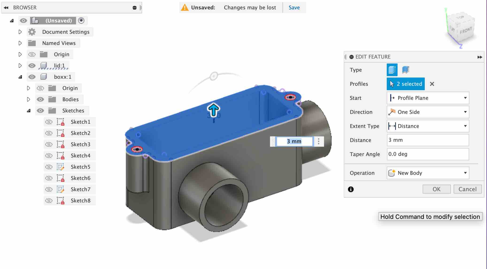
This completes the body. Now, to make the lid, we start a sketch on the top of the body. Typing P is the shortcut to “project.” We project the entire face and then extrude the sketch up by 3mm. Make sure to change the operation to “New Body” since the lid is separate from the main body.
To make the pid snap fits on the body, I added snaps on the lid:

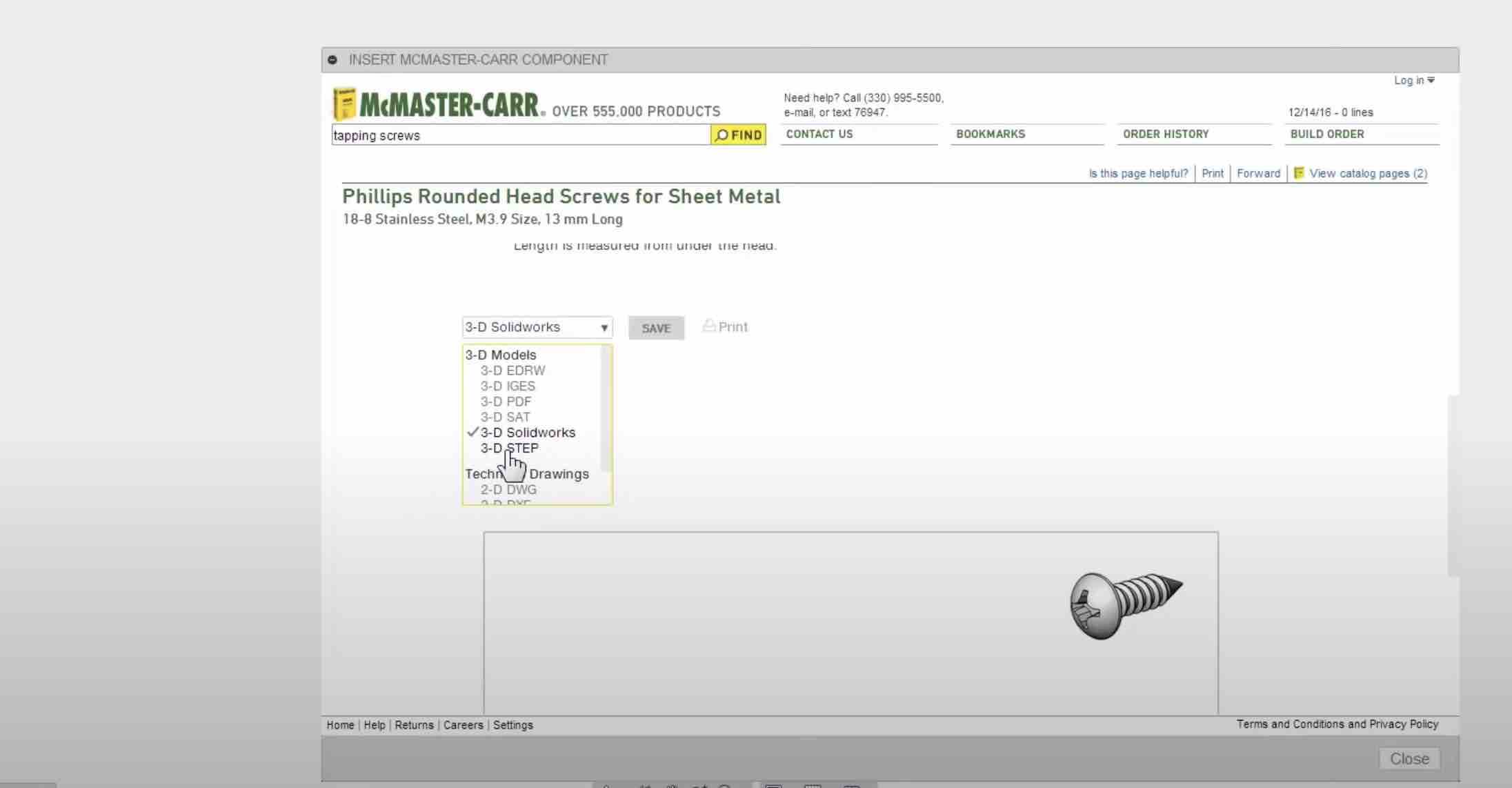
Finally to hold the lid down to the body, we add screws to the design. This can be done by going to the “Insert McMaster-Carr Component” option under the Insert tab.

This the screw that I chose. Be sure to choose the “3D STEP” option.
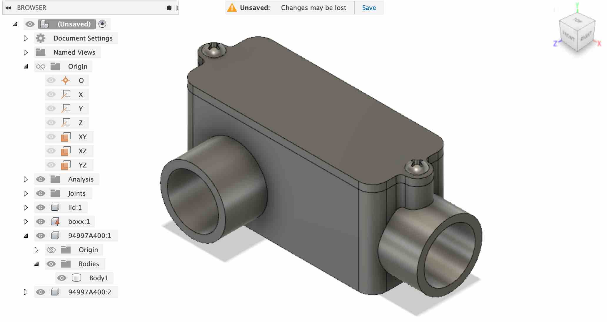
This is the finished product:
TinkerCAD
TinkerCAD is a free online CAD tool. It is a great software to introduce kids to the 3D design. I decided to opt for this software since I will be conducting a lot of 3D design and printing classes at the Super Fab Lab for school students and other beginners.
There are no downloads necessary for TinkerCAD, you just need to go to the website, create an account, and login. Once you are logged in you need to go to 3D designs -> create new design.
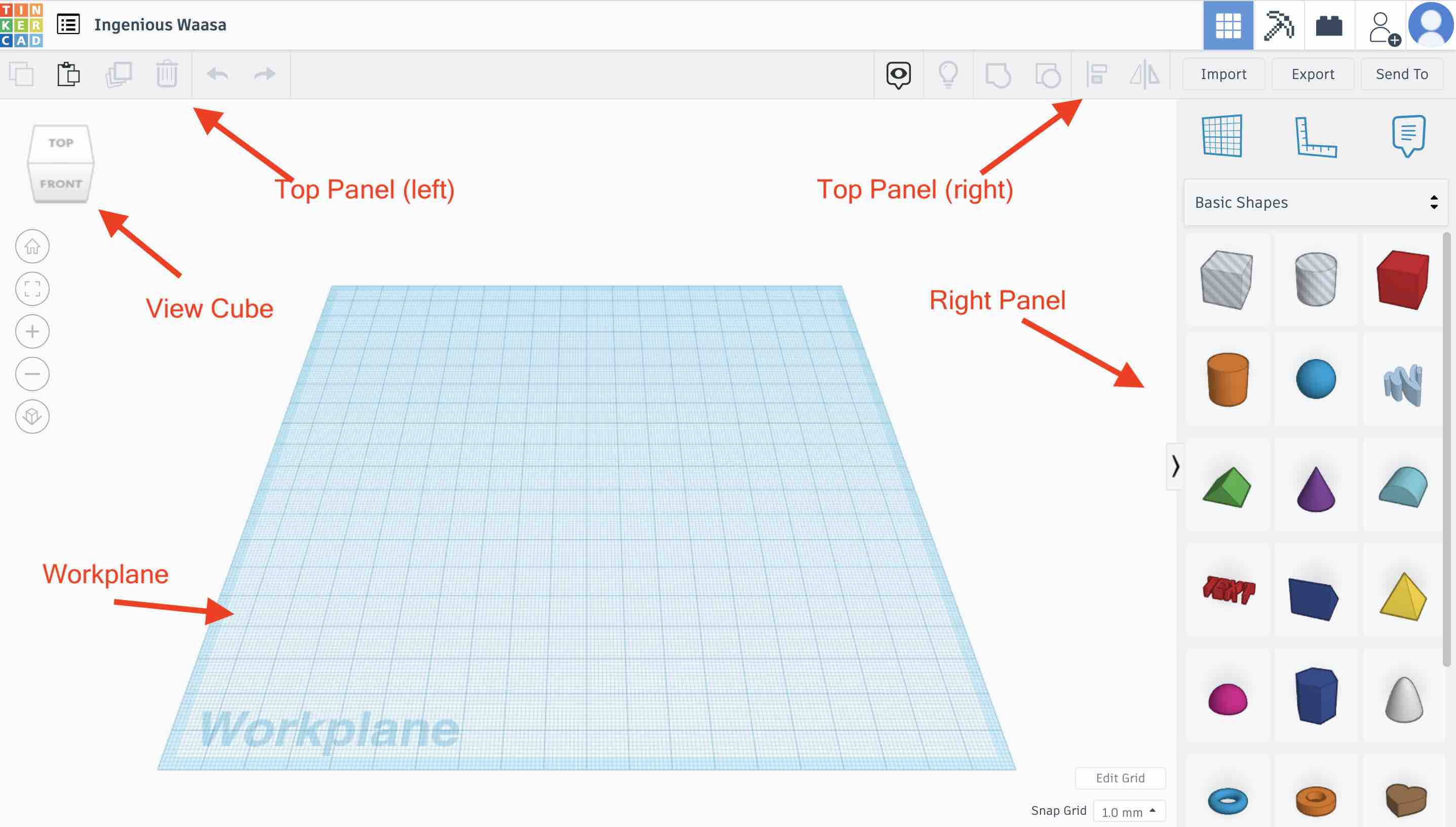
Workplane: The workplane sits in the middle. This is where you can place and model. In 2D design, a paper is where you print, in tinkerCAD this is where you canvas.
Viewcube and zooming: You can change the perspective of your deisgn using the viewcube. Scrooling will zoom in and out.
Right Panel: The right panel has basic shapes like cubes, cylinders and cones. If you click on the dropdown list there are more options like numbers, scenarys, characters, symbols, and hardware objects. On the top part of the right panel are options to change the workplane, the ruler tool and the notes tool.
Top Panel: There are two panels on top. One on the left and one on the right. THe right side top panel contains the basic operations we need to perform to build models. These include grouping, ungrouping, aligning and flipping models. The left side top panel has more recognizable fuctions such as copy, paste, duplicate and delete objects.
Designing a rocket: Divide and Conquer
The approach you take to designing something complicated is divide and conquer. Divide the deisgn into simple geometric pieces and then combine them. My aim is to deisign a rocket.
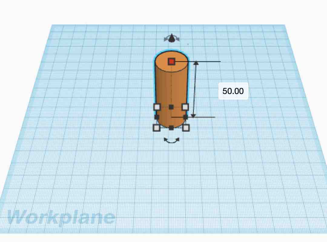
Step 1: Select cylinder and drop it on the work plane. The colour on each shape can be changed according to your preference. Ctrl+d will duplicate the object but we will not use that right now. We adjust the size of the cylinder or put in a dimension.
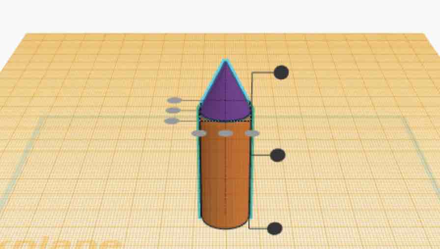
Step 2: Select new workplane from the right panel. drag it to the top of the cylinder. Drag and drop a cone on this plane. Press shift and select both the cylinder and the cone and align it using the align tool on the top right corner.
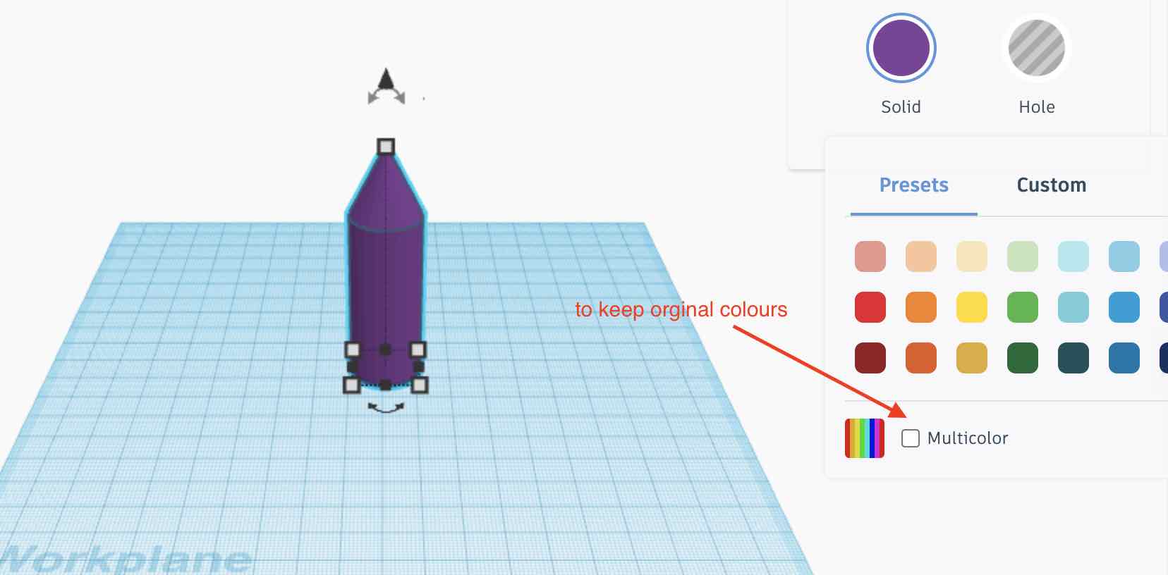
Step 3: Drag and drop a new workplane to the original place. Press shift and select both the shapes. Click on the group tool on the top right corner. This will make the colour of both the shapes the same. To keep different colours, open the colour bar and check multicolor design.
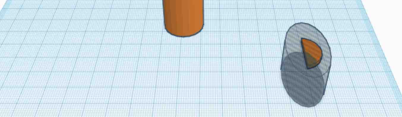
Step 4: To make the fins, we start with a cylinder and make it flat (~2mm in height). We then take the cube cut box (The transparent one in shapes) and position it to cut about half of the cylinder. Group the two shapes and the cylinder is cut. Now take the cylinder cut shape and cut out the bottom part to make the fin shape.

Step 5: Change the color of the tail to something distict from the other two colours. I chose black. Select the tail and press ctrl+d. This duplicates it. Rotate the copy 180 degrees and place it close to the cylinder. Select both the tail fins and rotate 180 degrees to stand the fins up. Align the fins to the center and bring it into the cylinder alittle bit. Group the two fins, duplicate it, and rotate 180 degrees so that now there are 4 fins. Align and group everything. Rocket is ready to export!

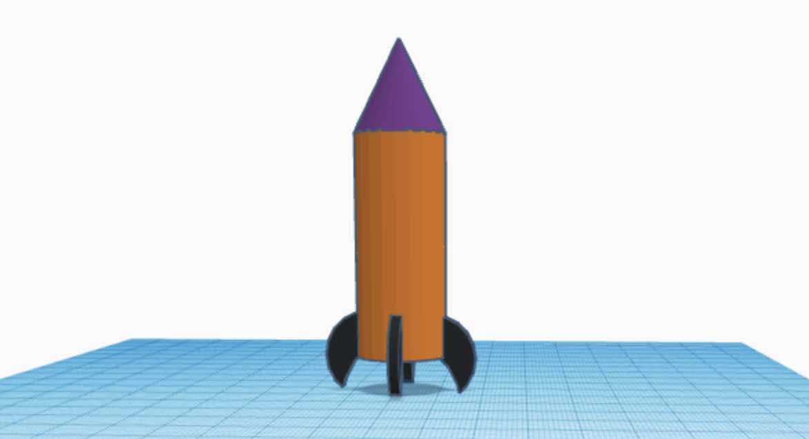
Image Compression
For image compression, I downloaded GIMP. However, I found it to be very similar to Preview. The only upside I saw in having GIMP was the option of adding BIMP as a plug-in and being able to compress multiple images at the same time. Therefore, I looked at a few tutorials to add BIMP. However, the code to add BIMP was taking a long time. The terminal window kept running and I think my computer was heating up. Therefore, I canceled the command. This is also when I realised that you could compress multiple images on Preview as well. So I decided to stick to Preview for image compression.
Preview is pretty straightforward and it comes preinstalled in macs. I am able to change the file type and also add arrows and text to images. This is a picture of exporting an image on preview, changing the file type to .jpeg, and compressing it to the least quality.

Design Files
Assessment Guide
Modelled experimental objects/part of a possible project in 2D and 3D software
Shown how you did it with words/images/screenshots
Included your original design files