11. Output devices (and KiCAD)
This week we went over output devices. Output devices are components that send data from a computer to a user or to another device. In lecture, we went over the different kinds of output devices that we can use in our projects. Some examples are different kinds of motors, LEDs, LCDs and speakers. Prior to this week, I was set on using an LCD in my final project. However, I was introduced to OLEDs during the lecture and think that it is a better option for my project. I was not able to work with OLEDs this week since it was not part of our “work-at-home” lab kit. This is for future consideration. For now I will work with the LCD.
During the Input Devices week, I was able to get a LCD (output device) to respond to a password on a keypad (input Device).
However I did not fully understand the workings of the 16X2 LCD. Therefore, this week I decided to focus on the workings of the LCD. As a group assignment we were required to measure the power consumed by an output device. I measured the power consumed by the LCD.
2022 Update
Since I am continuing with my final project idea from 2022, I decided to use servo motor as an output device. I used ATTiny45 as a microcontroller. I was able to get it to turn but there was some jitters in the servo motor.
Liquid Crystal Display
Liquid crystal display is a combination of two states of matter, the solid and the liquid. LCD uses a liquid crystal to produce a visible image. Liquid crystal displays are super-thin technology display screens that are generally used in laptop computer screens, TVs, cell phones and portable video games.
The one that I have is the 16x2 LCD. A 16x2 LCD means it can display 16 characters per line and there are 2 such lines. In this LCD each character is displayed in 5x7 pixel matrix. This LCD has two registers, namely, Command and Data. The command register stores the command instructions given to the LCD. A command is an instruction given to LCD to do a predefined task like initializing it, clearing its screen, setting the cursor position, controlling display etc. The data register stores the data to be displayed on the LCD. The data is the ASCII value of the character to be displayed on the LCD. Click to learn more about internal structure of a LCD.You can download the datasheet from Here.Here is the datasheet https://www.lumex.com/spec/LCM-S01602DTR-M.pdf
Here is the LCD pictured. The pictures were taken from this website.


To start off I followed along this tutorial. It was helpful with understanding what each pin does. Pictured is a labelled LCD:
The LCD has 16 pins. Here they are labelled:
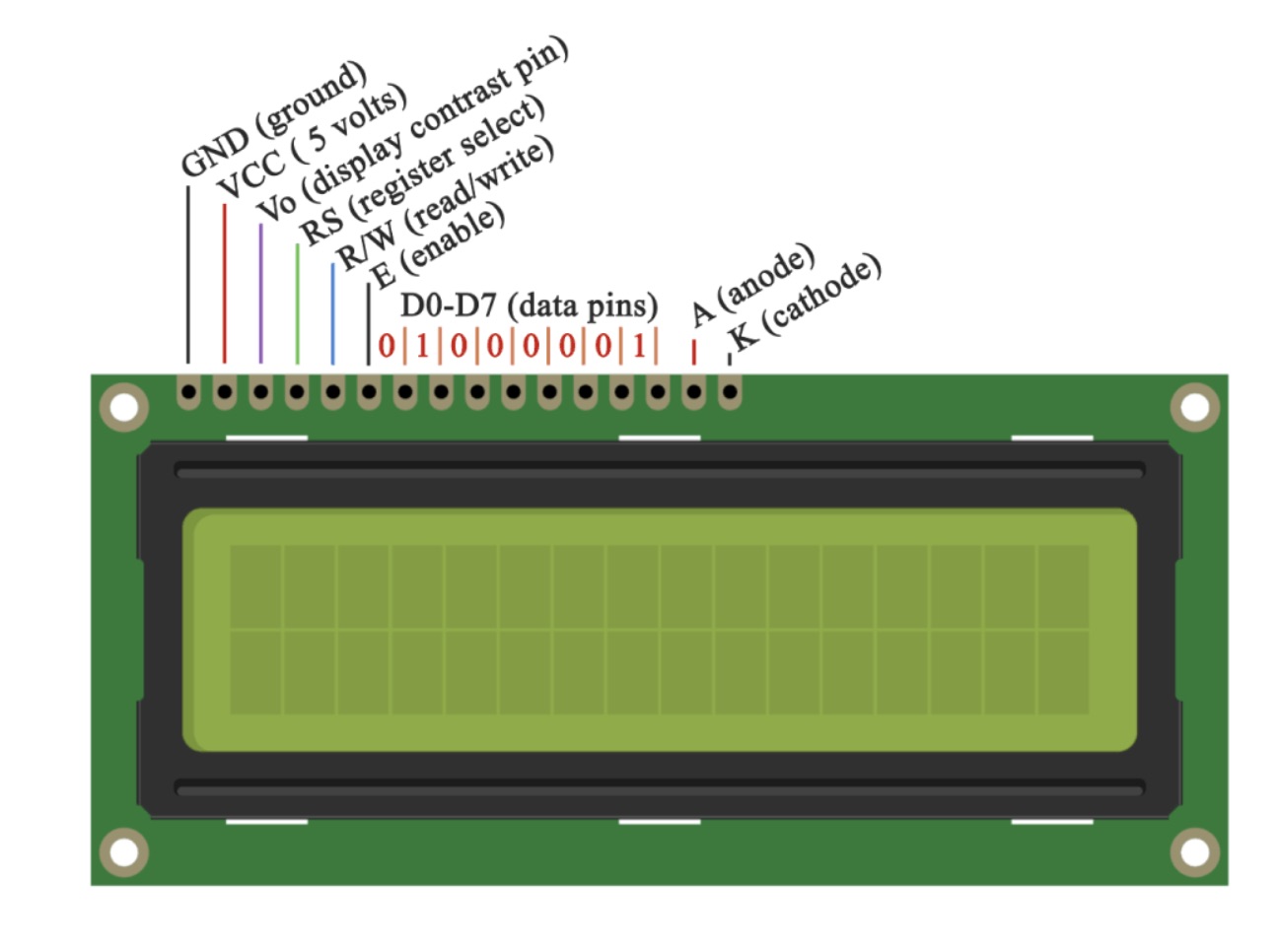
Pin 1: Ground
Pin 2: VCC (connects to the 5 volts pin on the Arduino Board)
Pin 3: Vo pin (connects to the potentiometer for controlling the contrast of the display)
Pin 4: RS pin or register select pin. Used to communicate whether we will send commands or data to the LCD. For example, if the RS pin is set on low state (0 volts), we can send commands like: set the cursor to a specific location, clear the display, turn off the display and so on. When the RS pin is set on High state (5 volts) we can send data or characters to the LCD.
Pin 5: R / W pin. Selects whether we will read or write to the LCD. Here the write mode is used for writing or sending commands and data to the LCD. The read mode is used by the LCD itself when executing the program.
Pin 6: The E pin. Enables the writing to the registers for the next 8 data pins from D0 to D7.
Pin 7-14: Data pins.Through these pins we are sending the 8 bits data when we are writing to the registers.
Pin 15: A or anode pin for the LED backlight
Pin 16: K or cathode pin for the LED backlight
Components required for the circuit
- 16x2 LCD screen
- Breadboard and wires
- Arduino Uno
- Potentiometer
- Battery
Circuit schematic
We will use just 6 digital input pins from the Arduino Board. The LCD’s registers from D4 to D7 will be connected to Arduino’s digital pins from 4 to 7. The Enable pin will be connected to pin number 2 and the RS pin will be connected to pin number 1. The R/W pin will be connected to Ground and the Vo pin will be connected to the potentiometer.

Code
First thing we need to do is it insert the Liquid Crystal Library. We can do that like this: Sketch > Include Library > Liquid Crystal. Then we have to create an LC object. The parameters of this object should be the numbers of the Digital Input pins of the Arduino Board respectively to the LCD’s pins as follow: (RS, Enable, D4, D5, D6, D7). In the setup we have to initialize the interface to the LCD and specify the dimensions of the display using the begin() function.
In the loop we write our main program. Using the print() function we print on the LCD. The setCursor() function is used for setting the location at which subsequent text written to the LCD will be displayed. The blink() function is used for displaying a blinking cursor and the noBlink() function for turning off. The cursor() function is used for displaying underscore cursor and the noCursor() function for turning off. Using the clear() function we can clear the LCD screen.
Here is the code for that I loaded into the microcontroller.
*/
#include <LiquidCrystal.h> // includes the LiquidCrystal Library
LiquidCrystal lcd(1, 2, 4, 5, 6, 7); // Creates an LC object. Parameters: (rs, enable, d4, d5, d6, d7)
void setup() {
 lcd.begin(16,2); // Initializes the interface to the LCD screen, and specifies the dimensions (width and height) of the display }
}
void loop() {
 lcd.print("Hello Fabacademy"); // Prints "Hello Fabacademy" on the LCD
 delay(3000); // 3 seconds delay
 lcd.clear(); // Clears the display
 lcd.print("This is my"); //
 lcd.setCursor(2,1); // Sets the location at which subsequent text written to the LCD will be displayed
 lcd.print("LCD Tutorial");
 delay(3000);
 lcd.clear(); // Clears the LCD screen
  lcd.print("Enter your"); //
 lcd.setCursor(2,1); // Sets the location at which subsequent text written to the LCD will be displayed
 lcd.print("password");
delay(3000);
lcd.clear();
 lcd.cursor(); // Displays an underscore (line) at the position to which the next character will be written
delay(3000);
lcd.noCursor(); // Hides the LCD cursor
 lcd.clear(); // Clears the LCD screen

}
Here is the final result:
2022 work: Servo Motor as an Output Device
Since my final project will use a servo motor as an output, I decided to work with it for this week. I chose to design it using the Attiny45 since the servo code doesn’t require much memory.
Servo Motor
The servo motor is a cheap and small motor that is simple to control. Therefore, I thought it would be perfect for my Fab Bag.
This tutorial was really helpful in understanding servos. It is basically a motor that uses feedback to control its position.
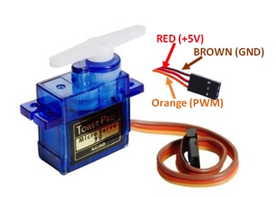
This is the pinout for the servo.
Designing the board
As a side outcome for this week, I learned KiCAD. Fran and Sibu is helping me with my assignments while setting up labs in Bhutan and they are very strong proponents for KiCAD. So I decided to learn it so that they would help me with my assignments.
Schematic
After downloading and installing Kicad, the procedure is similar to using EAGLE. First you need to install the Fab library on Kicad. The library can be downloaded here. This site also has good instructions on how to install it.
The schematic window is pretty straightforward. Here are some useful short cuts:
- A: Add component
- R: rotate component
- V: change value

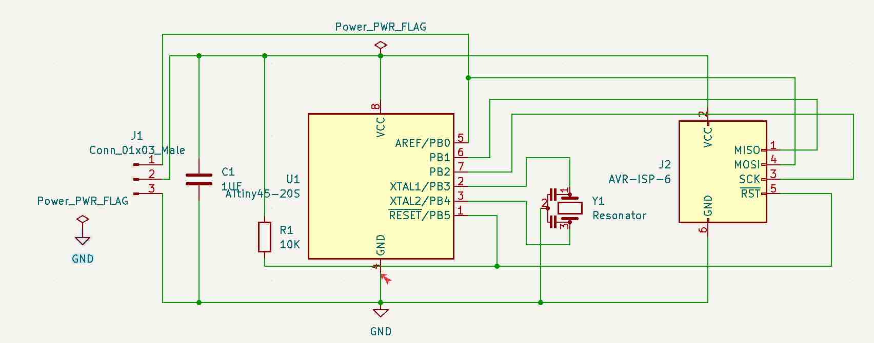
Once the connections are made, the next step is to annotate the components. This gives numbers to the compoments, next we assign footprints. Once this is done we change to PCB view and start routing. Make sure to run an electrical check before proceeding. (Inspect-> Electrical Rule Checker). I had one error.

I had forgotten to add a power flag to ground. I added it and this is my final schematic with no electrical errors:
PCB
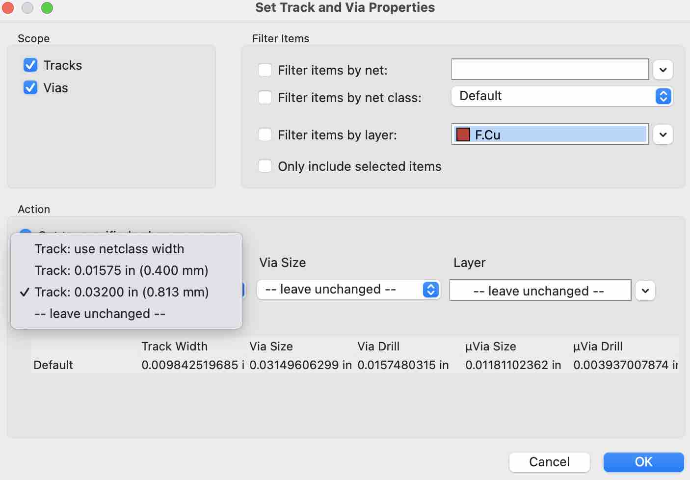
Once it switches to board view, orient the components in the desirable position and start routing the connections. Ensure that the track width is 0.4mm. Next, select edge cuts under appearance. This is where we draw the outline of the board. Ensure that the width of the edge is atleast 0.8mm.
After the board is designed, run a design rule checker. (inspect-> Design Rules checker.) There was no errors with my board. This is my final PCB design for this week:

Exporting images and converting to PNG
The first step is to convert the PCB drawing to .svg format. WE need to make two files; one for traces and one for the outline. To convert the traces follow this path:
- File -> plot
- Put in the file where you want to save the file in the output directory. Make sure to press no when it asks if you want to save in a relative path.
- Select svg in plot format
- Check plot Edge Cuts on all layers
- Check Negative plot
- Check Check zone fills before plotting
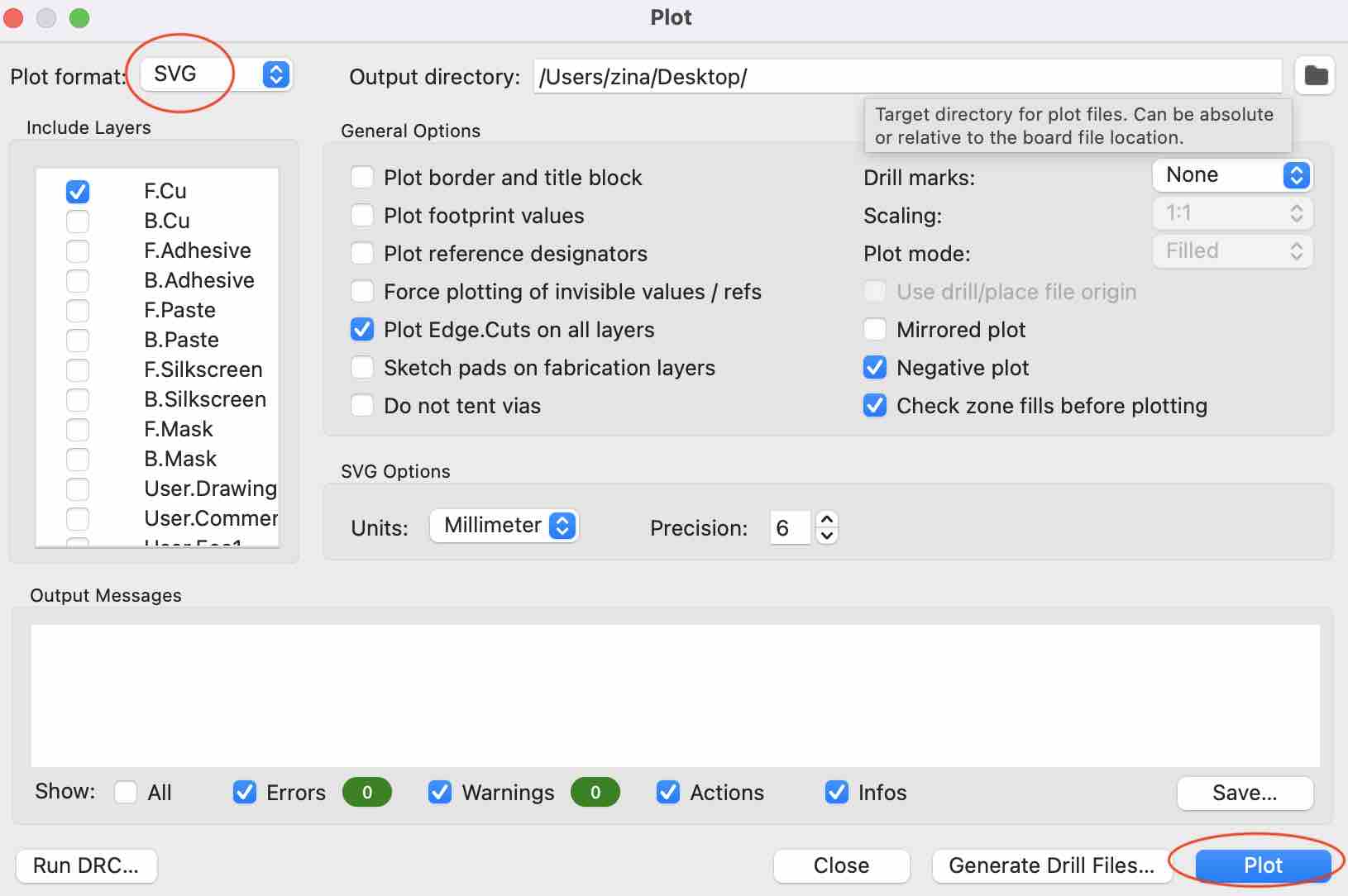
Now, click plot. This automatically saves the .svg file. Follow the same procedure for saving the outline file. Make these changes:
- Deselect F.Cu from Include layers and select Edge.Cuts
- Uncheck negative plot
- click plot.
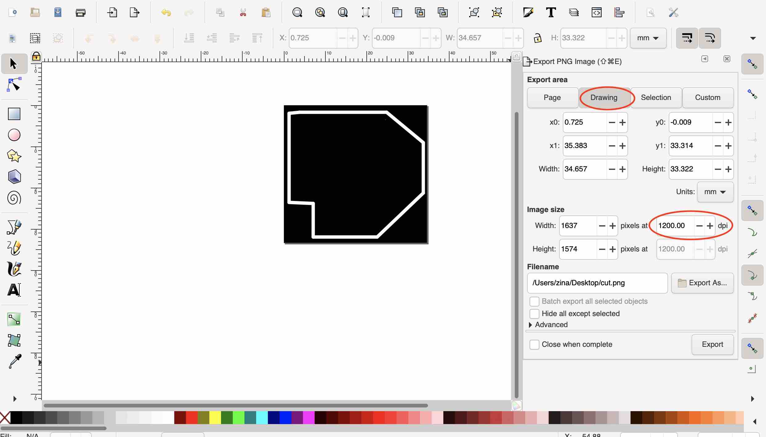
Now, both the .svg files should be saved. The next step is to convert the svg files to png files. For this we need to open the images on inkscape. Follow these steps:
- Open svg image on Inkscape.
- Go to file -> Document Properties -> Resize page to drawing/ selection
- File -> Export PNG Image
- Go to drawing tab, change dpi to 1200
- Select the correct file path to save
- Export
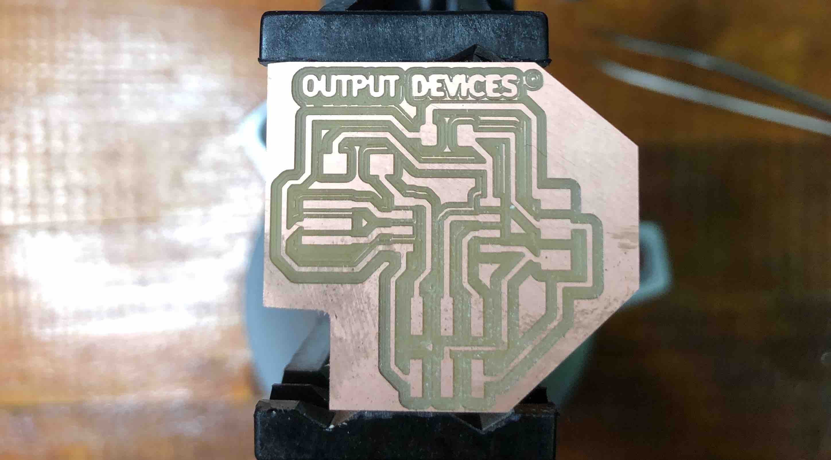
Do this for both the traces and outline file and then proceed with milling and stuffing. Here is my milled board:
List of components required for soldering:
- Attiny 45
- 2X3 AVRISP
- 10k resistor
- 1 uf capacitor
- 1X3 connector
- Resonator
Programming
This was the hardest part about this week. With an arduino its easy to program and reprogram the board before milling and soldering. However, in this case, I had to program only after having the board ready. One of the problems I had is that many of the example codes used a library (such as SofwareSerial and SoftwareServo) For some reason this was not getting uploaded to my board. I still need to figure out the reason for this issue. I finally found a code that controls the servo motor without a library. Here it is:
void setup()

{

  pinMode(0, OUTPUT);

}

void loop()

{

    for (int i = 0; i < 90; ++i) {

      digitalWrite(0, HIGH);
      delayMicroseconds(2000);

      digitalWrite(0, LOW);
      delayMicroseconds(18000);

    }

    for (int i = 0; i < 90; ++i)

    {

      digitalWrite(0, HIGH);
      delayMicroseconds(1000);

      digitalWrite(0, LOW);
      delayMicroseconds(19000);

  }

}
Group Assignment.
Part of the assignment for the week was to find out the power consumption of one of the output devices. I decided to figure out the power consumption of the LCD screen. I did this by attaching an ammeter in series to the circuit before the ground connection. This will give me a current value. To find out the voltage value, I connected a 9V battery as the power source.
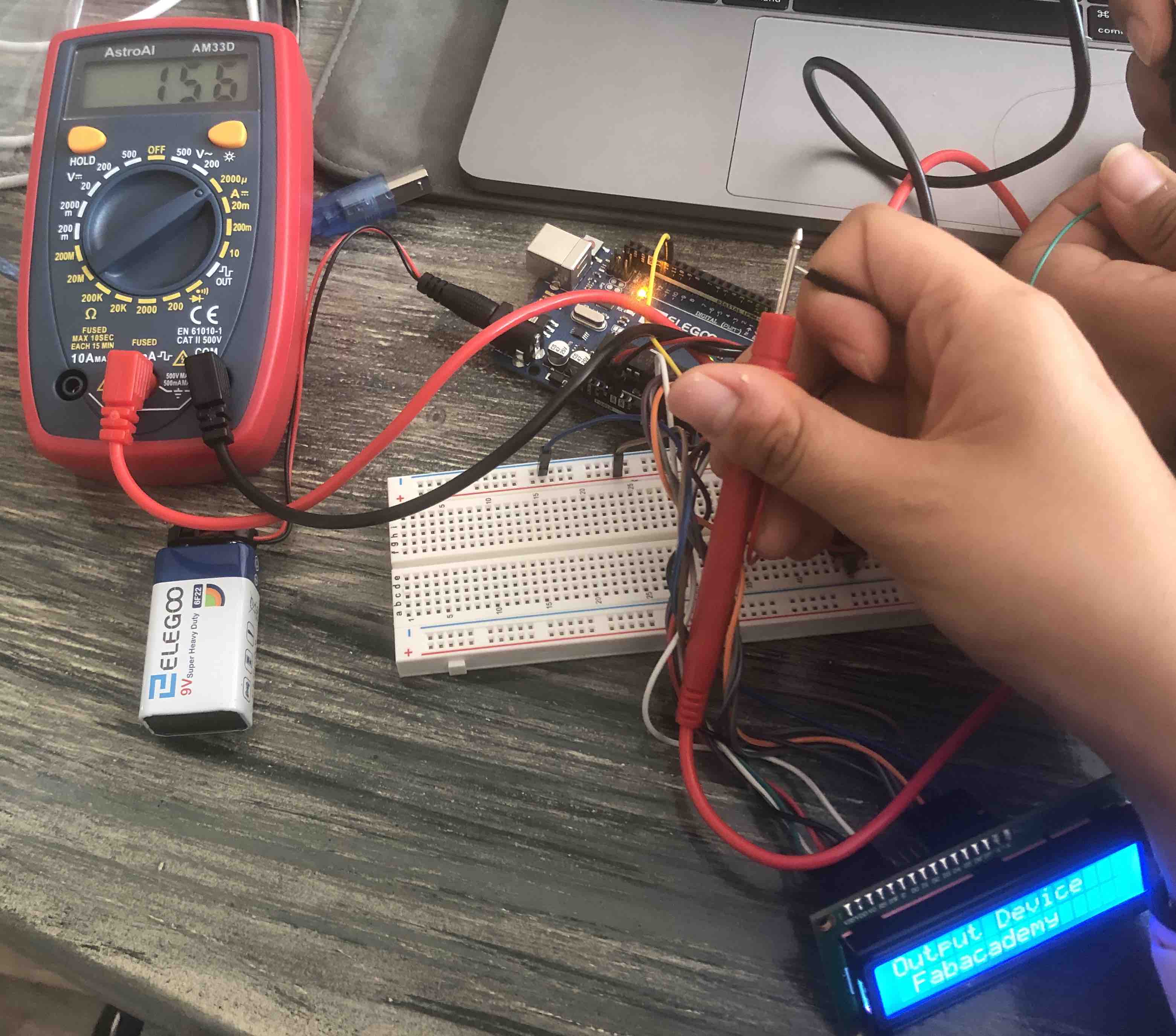
From the reading above, we have a current value of 0.156 mA. With a known voltage value of 9V, we can calculate the power consumption:
P = V*I = 9V * 0.000156 A = 0.0014 Watts = 1.4 mW.