Circuit Design and Programming
Main Controller
I used Module Generic Seed Xiao esp32-C3 SMD
Output
Solenoid valve, Pump, Display(I2C LCD) LEDs
Input Devices
Flow rate sensor Turbidity Sensor
Design
In designing, I used KiCad software and Roland SRM-20 machine for milling and V bit 40 deg for milling and 0.8mm bit for edge cuts.
Schematic Design
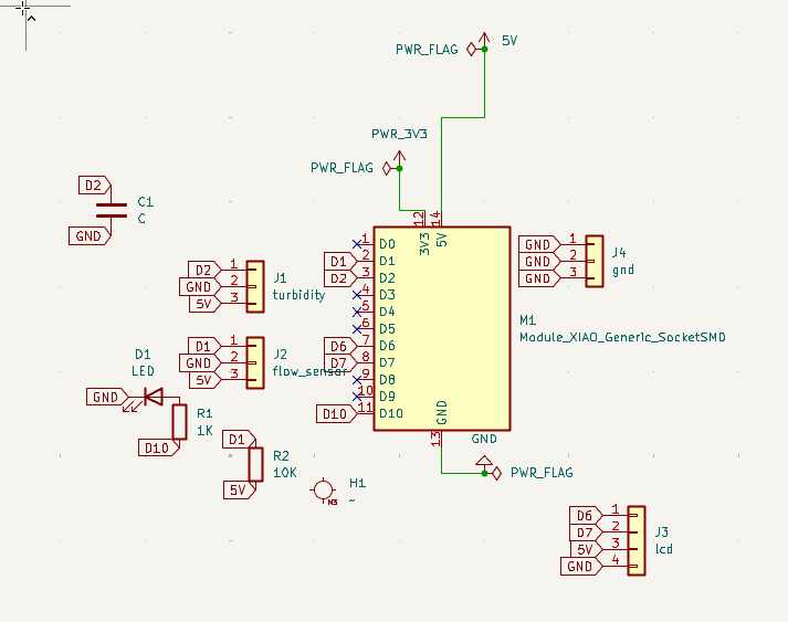
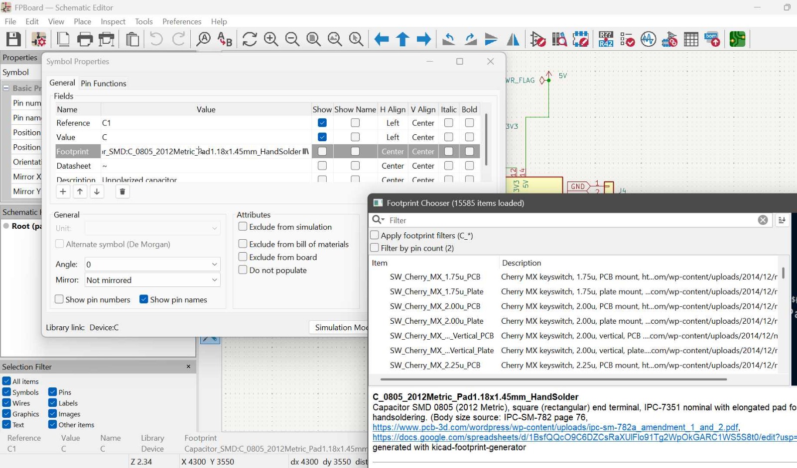
To assign footprints to my components, I added the components first from the library by pressing A then I right click and go to properties then under foot print and search the exact footprint of the componet am using.To know my components footprint i was searching the model and datasheet on the internet
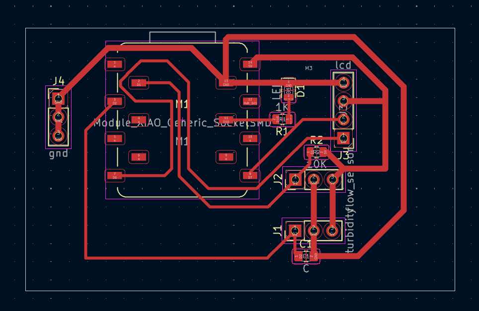
My Design,
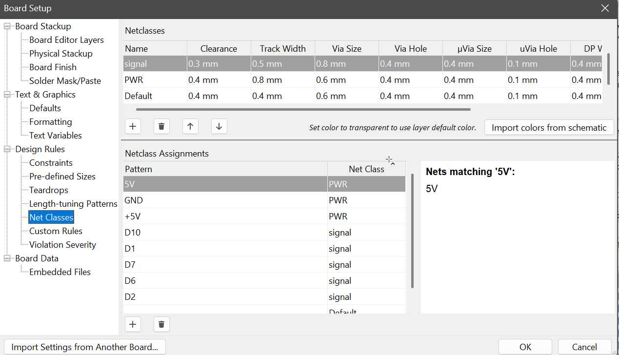
Under board setup was able to assing the minimum track widg and clearences
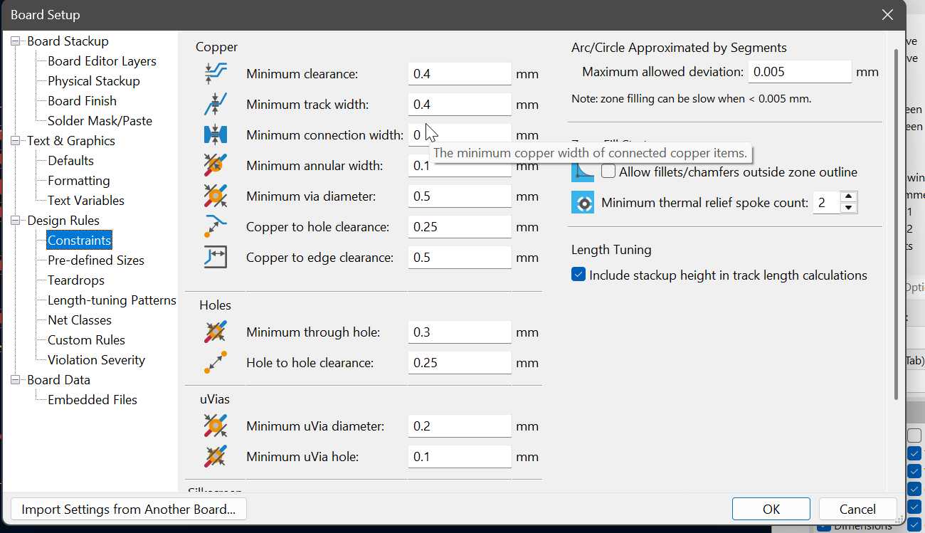
Since power traces must be thicker than signal traces, i assinged them netclasses and that is waht I used.
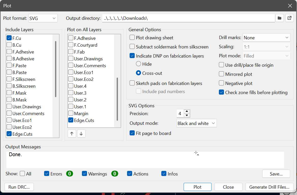
During ploting, i ploted SVG files for F.Cu and edge cuts and ensured i marked the fill page to baord to give me easy time in modsproject.
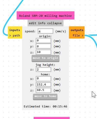
In mods I selected the my machine Roland SRM-20, then selected my tool (V bit 40 deg), then i click calculate to get the cut depth , max depth and tool diameter before i customize.
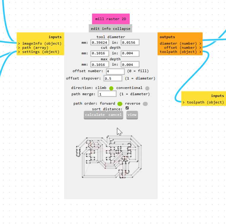
In mods i always set x and y to 0, i dont use its default values.
Main Board files
These are my files
Edge cut Gerber file F.CU gerber
 F.Cu rml fileedgecut
Please refer to my electronic production week to get the milling cutting process.
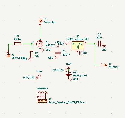
Power Board
Schematic design
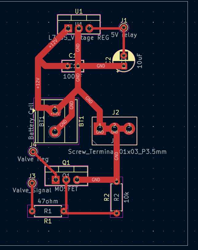
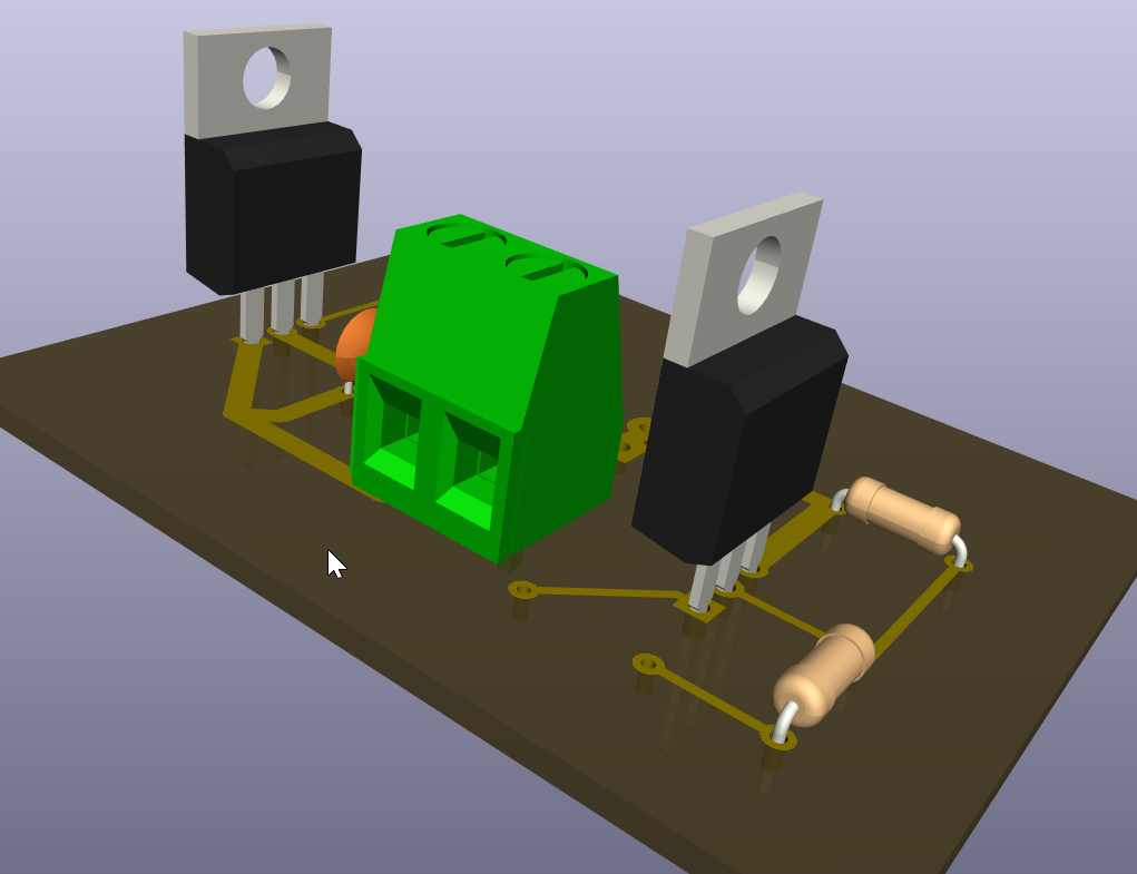
3D view
Voltage Regulator
An LM7805 voltage regulator was used to convert the 12V supply to a regulated 5V output. This 5V supply was used to power the loads(control circuitry,12v pump and 12v solenoid valve). I ised 10µF capacitor connected to the regulator output to improve voltage stability and reduce fluctuations.
MOSFET Switching Circuit
An N-channel MOSFET was used as an electronic switch to control the 12V solenoid valve. The gate was connected to the controller output through a 47Ω resistor, while a 10kΩ pull-down resistor was connected between the gate and ground to keep the MOSFET OFF when no signal was present. The drain was connected to the valve’s negative terminal and the source to ground. When a control signal was applied, the MOSFET turned ON and allowed current to flow through the valve.
Solenoid Valve Connection
The positive terminal of the 12V solenoid valve was connected directly to the 12V supply. The negative terminal was connected to the MOSFET drain. This allowed the controller to switch the valve ON and OFF through the MOSFET.
Pump Connection
The 12V water pump was connected in parallel with the solenoid valve. The positive terminal was connected directly to the 12V supply, while the negative terminal was connected to the MOSFET drain. As a result, both the pump and valve could be controlled simultaneously using a single MOSFET.
Power Filtering
A 100nF capacitor was connected across the main 12V supply line to reduce electrical noise and improve the stability of the power circuit.
Programming
#include <Wire.h>
#include <LiquidCrystal_I2C.h>
#include <WiFi.h>
#include <PubSubClient.h>

// ================= LCD =================
LiquidCrystal_I2C lcd(0x27, 16, 2);

// ================= WiFi =================
const char* ssid = "MT";
const char* password = "#@Innovate";

// ================= MQTT =================
const char* mqtt_server = "broker.emqx.io";

WiFiClient espClient;
PubSubClient client(espClient);

// ================= Pins =================
const int turbidityPin = A2;
const int CONTROL_PIN = D10;      // Active LOW output
const int flowPin = D2;           // Flow sensor pin

// ================= Turbidity Calibration =================
float V_clean = 2.77;
float V_dirty = 0.90;

// ================= Flow Variables =================
volatile int pulseCount = 0;

float flowRate = 0.0;
float totalLiters = 0.0;

unsigned long previousMillis = 0;

// =====================================================
// Interrupt for Flow Sensor
// =====================================================
void IRAM_ATTR pulseCounter() {
  pulseCount++;
}

// =====================================================
// Average Turbidity Reading
// =====================================================
int getAverage() {
  int sum = 0;

  for (int i = 0; i < 20; i++) {
    sum += analogRead(turbidityPin);
    delay(5);
  }

  return sum / 20;
}

// =====================================================
// WiFi Connection
// =====================================================
void setup_wifi() {

  Serial.print("Connecting to WiFi");

  WiFi.begin(ssid, password);

  while (WiFi.status() != WL_CONNECTED) {
    delay(500);
    Serial.print(".");
  }

  Serial.println("\nWiFi connected");
  Serial.println(WiFi.localIP());
}

// =====================================================
// MQTT Reconnection
// =====================================================
void reconnect() {

  while (!client.connected()) {

    Serial.print("Connecting MQTT...");

    if (client.connect("ESP32WaterPurifier")) {

      Serial.println("Connected");

    } else {

      Serial.print("Failed, rc=");
      Serial.print(client.state());
      Serial.println(" Retrying...");

      delay(2000);
    }
  }
}

// =====================================================
// Setup
// =====================================================
void setup() {

  Serial.begin(115200);

  pinMode(CONTROL_PIN, OUTPUT);
  digitalWrite(CONTROL_PIN, HIGH);   // Default OFF

  pinMode(flowPin, INPUT_PULLUP);
  attachInterrupt(digitalPinToInterrupt(flowPin),
                  pulseCounter,
                  FALLING);

  Wire.begin(D6, D7);

  lcd.init();
  lcd.backlight();

  lcd.clear();
  lcd.setCursor(0, 0);
  lcd.print("Water Purifier");
  lcd.setCursor(0, 1);
  lcd.print("Starting...");
  delay(2000);

  setup_wifi();

  client.setServer(mqtt_server, 1883);

  Serial.println("=== SYSTEM READY ===");
}

// =====================================================
// Loop
// =====================================================
void loop() {

  if (!client.connected()) {
    reconnect();
  }

  client.loop();

  // ================= TURBIDITY =================
  int raw = getAverage();

  float voltage = raw * (3.3 / 4095.0);

  float turbidity =
      ((V_clean - voltage) /
       (V_clean - V_dirty)) * 100.0;

  // Clamp values
  if (turbidity < 0) turbidity = 0;
  if (turbidity > 100) turbidity = 100;

  String status;

  // ================= Decision Logic =================
  if (turbidity < 20) {

    status = "CLEAN";

    // Active LOW output OFF
    digitalWrite(CONTROL_PIN, HIGH);

  }
  else if (turbidity < 50) {

    status = "SLIGHT DIRTY";

    digitalWrite(CONTROL_PIN, LOW);

  }
  else if (turbidity < 80) {

    status = "DIRTY";

    digitalWrite(CONTROL_PIN, LOW);

  }
  else {

    status = "VERY DIRTY";

    digitalWrite(CONTROL_PIN, LOW);
  }

  // ================= FLOW SENSOR =================
  unsigned long currentMillis = millis();

  if (currentMillis - previousMillis >= 1000) {

    previousMillis = currentMillis;

    // YF-S201 calibration factor
    flowRate = pulseCount / 7.5;

    float litersThisSecond = flowRate / 60.0;

    totalLiters += litersThisSecond;

    pulseCount = 0;

    // MQTT Messages
    char flowMsg[20];
    char totalMsg[20];
    char turbidityMsg[20];

    sprintf(flowMsg, "%.2f", flowRate);
    sprintf(totalMsg, "%.2f", totalLiters);
    sprintf(turbidityMsg, "%.1f", turbidity);

    // ================= MQTT Publish =================
    client.publish("water/flow", flowMsg);
    client.publish("water/total", totalMsg);
    client.publish("water/turbidity", turbidityMsg);
    client.publish("water/status", status.c_str());

    // ================= Serial =================
    Serial.print("Turbidity: ");
    Serial.print(turbidity, 1);
    Serial.print("% | ");
    Serial.print(status);

    Serial.print(" | Flow: ");
    Serial.print(flowRate);
    Serial.print(" L/min");

    Serial.print(" | Total: ");
    Serial.print(totalLiters);
    Serial.println(" L");

    // ================= LCD =================
    lcd.clear();

    lcd.setCursor(0, 0);
    lcd.print("T:");
    lcd.print((int)turbidity);
    lcd.print("% ");

    if (turbidity < 20)
      lcd.print("RUN");
    else
      lcd.print("STOP");

    lcd.setCursor(0, 1);
    lcd.print("F:");
    lcd.print(flowRate, 1);
    lcd.print("L/m");
  }
}
I generated the above code using chatgpt using the following prompt;
Develop a single Arduino sketch for the Seeed Studio XIAO ESP32 that combines the existing turbidity monitoring system with a YF-S201 flow sensor and MQTT communication. The system should read turbidity from A2, measure flow rate and total volume using the flow sensor on D2, display turbidity status and flow information on a 16×2 I2C LCD (SDA = D6, SCL = D7), connect to Wi-Fi and publish flow rate, total liters, turbidity percentage, and water quality status to an MQTT broker every second. The valve/MOSFET connected to D10 should be controlled using active-low logic based on the turbidity level.
Files

