Final Project: Water for Aduvan
Final Project Presentation
The final project presentation explains the motivation, system architecture, design process, implementation, testing, results, and future development of Water for Aduvan.
View / Download Final Project Presentation
Final Project Video
The video demonstrates the Water for Aduvan system, including the water treatment process, electronic control system, sensors, automated valves, and IoT monitoring dashboard.
Project Documentation
The following pages contain the detailed documentation for the project:
- Project Concept
- Circuit Design and Programming
- Sensors
- Physical Components and Fabrication
- Project Tracker
What does it do?
Water for Aduvan is a smart, modular water purification and monitoring system designed to improve access to safer drinking water in underserved communities.
The system combines physical filtration, water-quality sensing, automated flow control, embedded electronics, and IoT monitoring. The system monitors water conditions and uses an ESP32-based controller to manage pumps and solenoid valves.
The current prototype focuses on filtration, turbidity monitoring, flow monitoring, automated water routing, and remote monitoring.
Future development will integrate additional treatment technologies, including electrocoagulation and photocatalytic treatment, through planned collaboration and further experimentation.
The system follows a modular architecture so that treatment, sensing, control, and monitoring components can be independently improved or replaced.
Main system functions
- Water filtration
- Turbidity monitoring
- Flow-rate monitoring
- Automated pump control
- Automated solenoid-valve control
- ESP32-based embedded control
- MQTT/IoT communication
- Remote dashboard monitoring
- Local system status monitoring
- Modular physical construction
Who has done what beforehand?
Water purification and water-quality monitoring systems have been developed using technologies such as physical filtration, reverse osmosis, electrocoagulation, photocatalysis, embedded systems, and IoT monitoring.
Existing systems provided useful references for the design of Water for Aduvan. However, many water-treatment systems are designed for larger installations or depend on components and infrastructure that can be difficult to maintain in rural communities.
Water for Aduvan explores how digital fabrication, embedded electronics, sensors, and IoT technologies can be combined into a lower-cost and locally maintainable system.
The project is particularly interested in:
- Affordable water-treatment technologies
- Local fabrication
- Automated monitoring
- Community-scale deployment
- Modular system architecture
- Real-time water-quality information
- Future integration of advanced treatment technologies
What did you design?
I designed and developed several mechanical, electronic, software, and system-level components.
1. Sensor mounting and housing
Custom mounting components were designed to position and protect the sensors within the water-treatment system.
The designs were developed to make sensor installation, maintenance, and replacement easier.
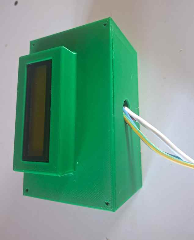
2. Electronics control box
A custom enclosure was designed to contain the electronic control system.
The enclosure houses components including:
- ESP32 controller
- Power regulation components
- Relay/control electronics
- Sensor connections
- Pump and valve control connections
- Wiring and connectors
3. Custom control PCB
A custom PCB was designed to organize the connections between the microcontroller, sensors, power system, and actuators.
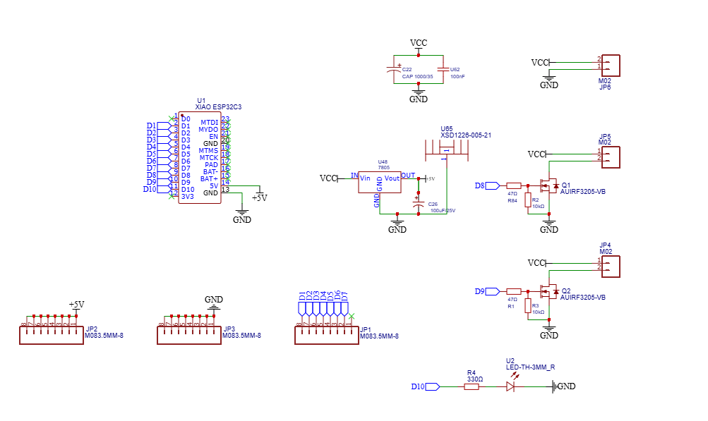
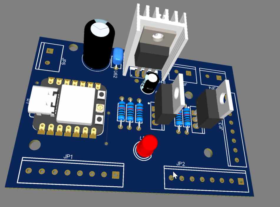
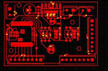
The PCB was fabricated and assembled as part of the electronics development process.
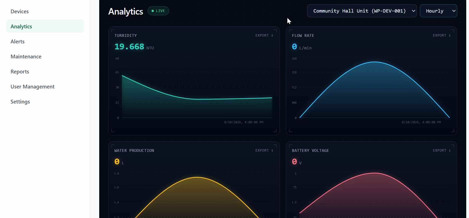
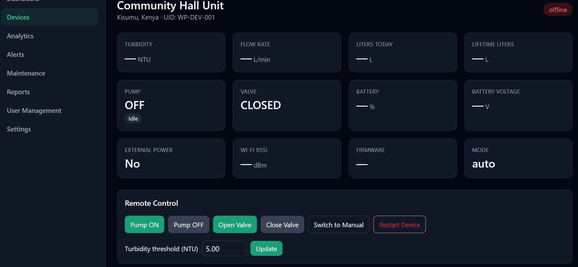
4. IoT dashboard
A dashboard was developed to visualize system information and support remote monitoring.
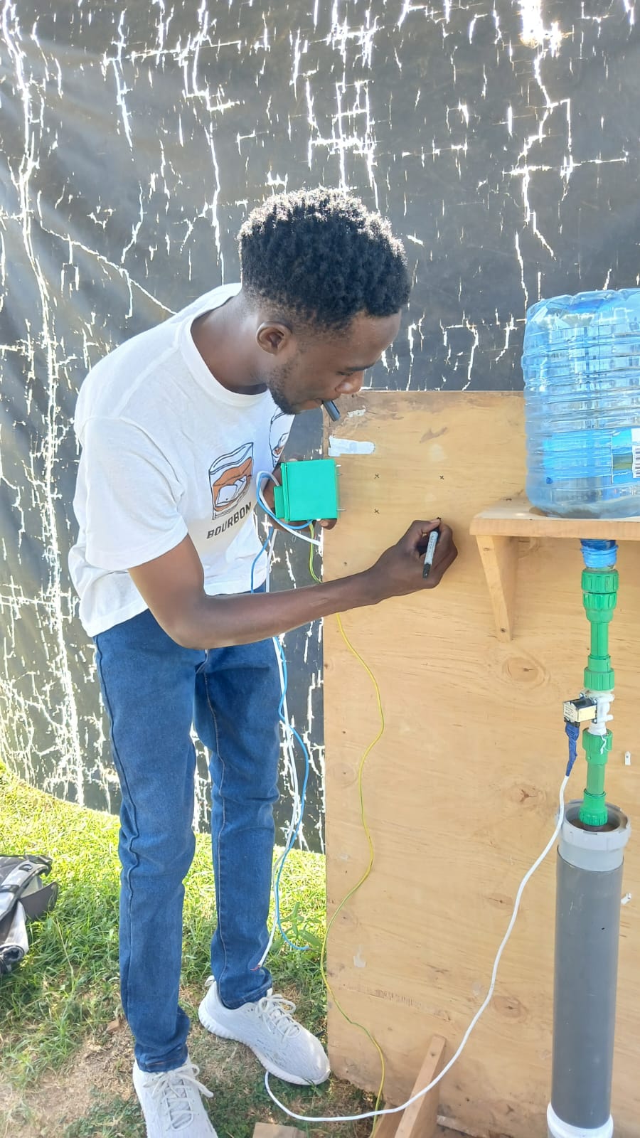
5. Water-treatment system layout
The plumbing and treatment modules were arranged to provide a controlled path for water through the system.
What sources did you use?
The project was informed by technical documentation, research, previous projects, and component documentation.
Sources included:
- Fab Academy documentation
- Previous Fab Academy final projects
- ESP32 documentation
- Sensor manufacturer datasheets
- IoT and MQTT documentation
- Research publications
- ResearchGate
- Wikipedia for preliminary background research
- YouTube tutorials and technical demonstrations
- ChatGPT for technical guidance, debugging assistance, explanations, and development support
- WHO drinking-water guidance and related water-quality references
Technical information from online sources was compared with component datasheets and practical testing wherever possible.
What materials and components were used?
Mechanical components
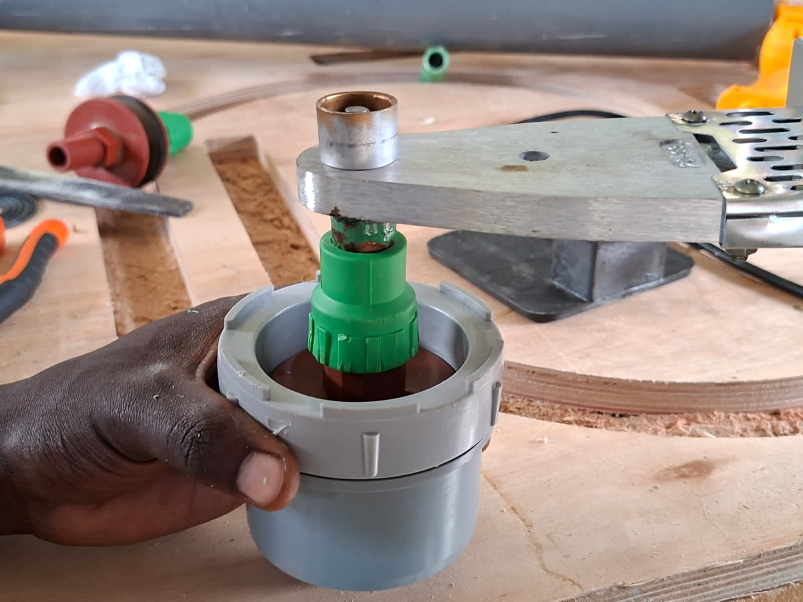
- PVC pipes and fittings
- PPR pipe and fittings
- Acrylic
- Fasteners
- Filtration media
- Sand
- Gravel/pebbles
- Activated/biochar filtration media
- Photocatalytic materials for future development
- 3D-printed components
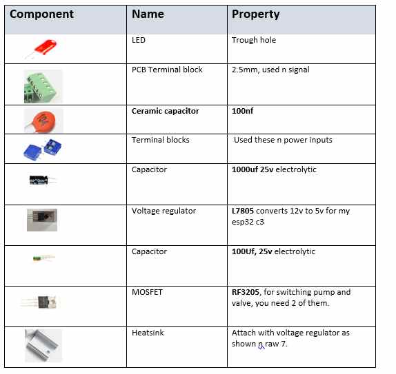
Electronic components
- ESP32 microcontroller
- Turbidity sensor
- Flow-rate sensor
- Solenoid valve
- Water pump
- Relay/control components
- LCD display
- DC-DC buck converters
- Custom PCB
- Wiring and connectors
- Power supply/battery components
Where did the materials and components come from?
Electronic components were obtained from a combination of:
- Fab Lab Winam inventory
- Local electronics suppliers
- Online marketplaces
- Components sourced through project partners and international suppliers
Mechanical materials were obtained mainly from:
- Local hardware stores in Kisumu
- Plumbing suppliers
- Electronics suppliers
- Fab Lab Winam fabrication facilities
The project intentionally used materials and components that can be sourced or substituted locally where possible.
How much did it cost?
The estimated prototype cost was approximately KES 16,900.
| Item | Estimated Cost (KES) |
|---|---|
| ESP32-S2 Mini | 1,200 |
| Turbidity Sensor | 1,500 |
| Flow Sensor | 800 |
| Solenoid Valve | 1,500 |
| Relay Module | 400 |
| PCB Materials | 1,000 |
| Aluminium Electrodes | 1,500 |
| Acrylic and Fabrication Materials | 3,000 |
| Filtration Media | 2,000 |
| Plumbing Components | 2,500 |
| Miscellaneous | 1,500 |
| Total | 16,900 |
The cost represents the prototype and does not necessarily represent the expected cost of a future optimized production version.
What parts and systems were made?
Water-treatment system
The physical treatment system was assembled from several modular sections.
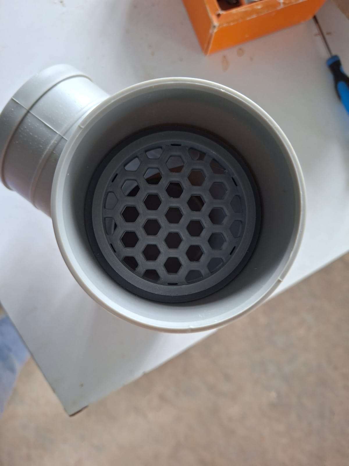
Sediment holder
A sediment/screening component was developed to remove larger particles before water enters the finer filtration stages.
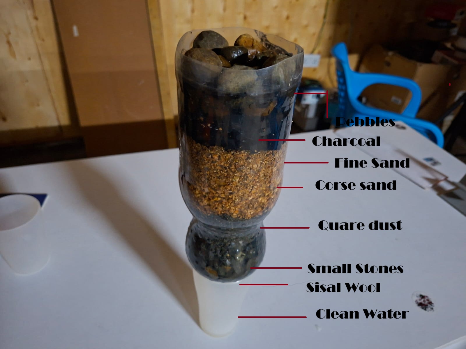
Filtration chamber
A filtration chamber was constructed using locally available materials and filtration media.
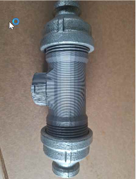
Sensor holder
A custom sensor holder was developed to position the water-quality sensor in the appropriate section of the system.
Electronics system
The electronics system provides sensing, control, power management, and communication.
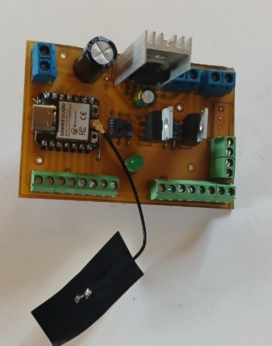
The system includes:
- ESP32 controller
- Sensor inputs
- Pump control
- Solenoid-valve control
- Power regulation
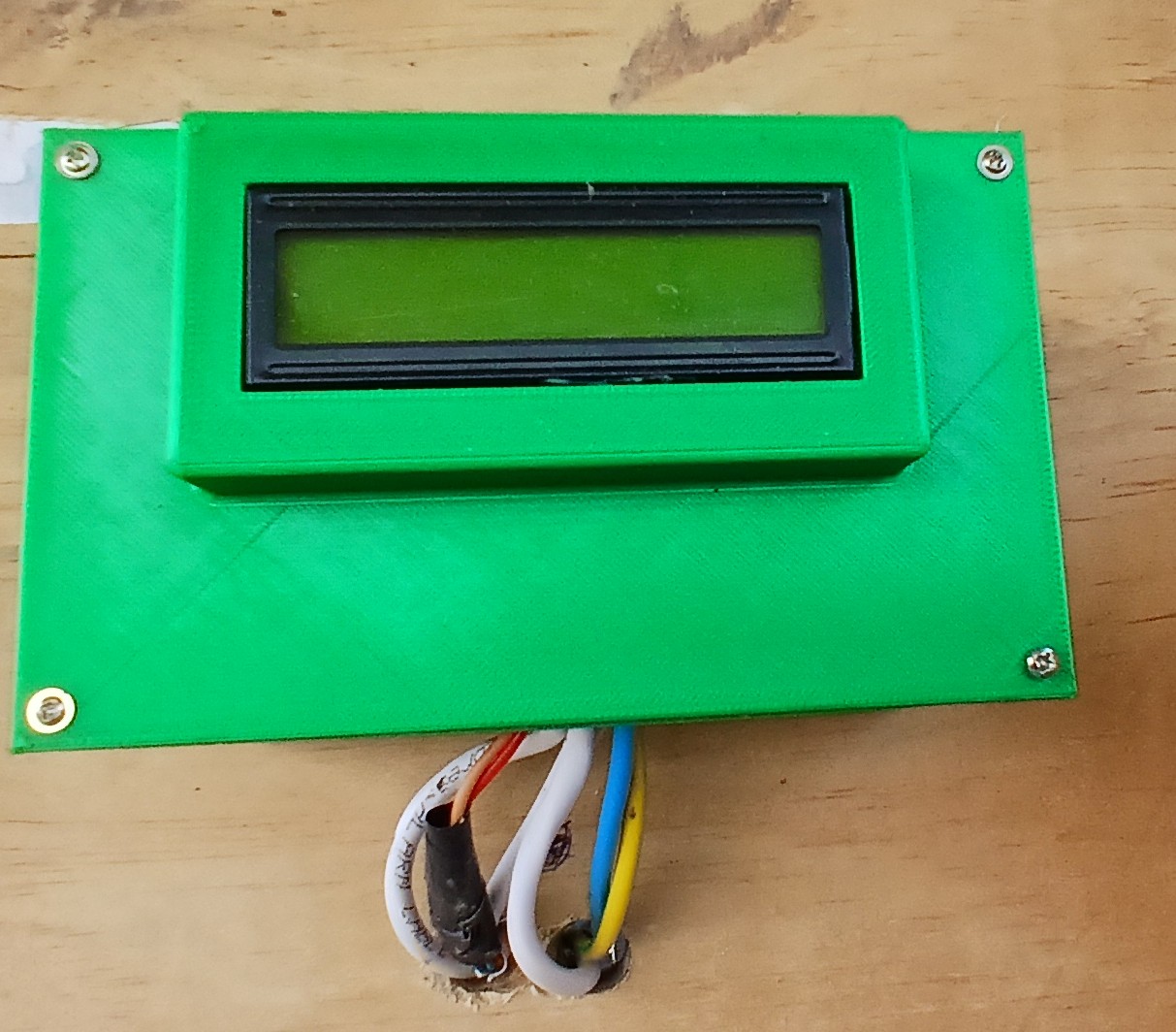
- Local display
- IoT communication
Software system
The software system consists of:
- ESP32 embedded firmware
- Sensor data acquisition
- Sensor processing
- Automated control logic
- MQTT communication
- IoT dashboard
- System monitoring
The embedded controller receives sensor information and uses programmed logic to control the water-treatment system.
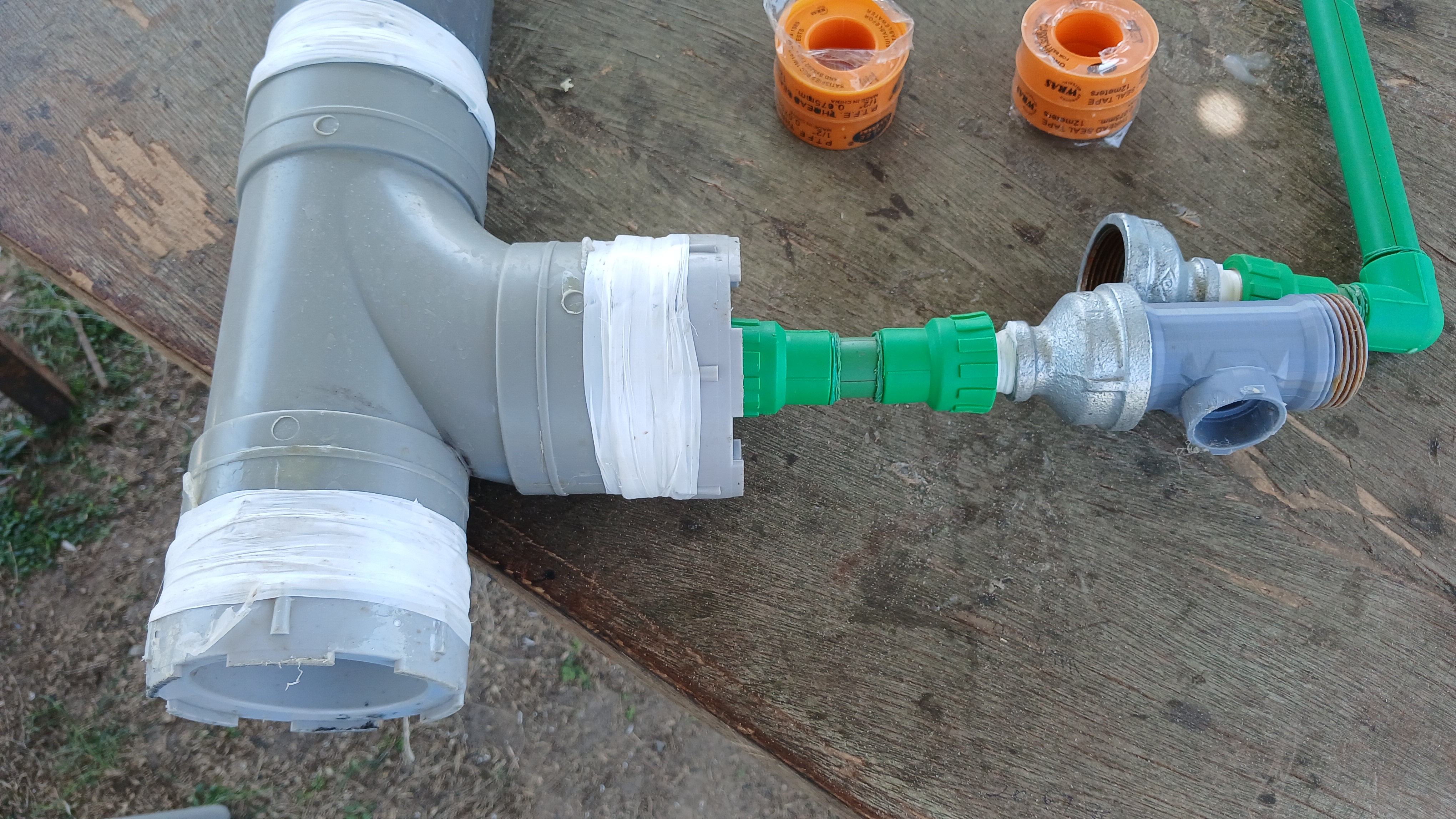
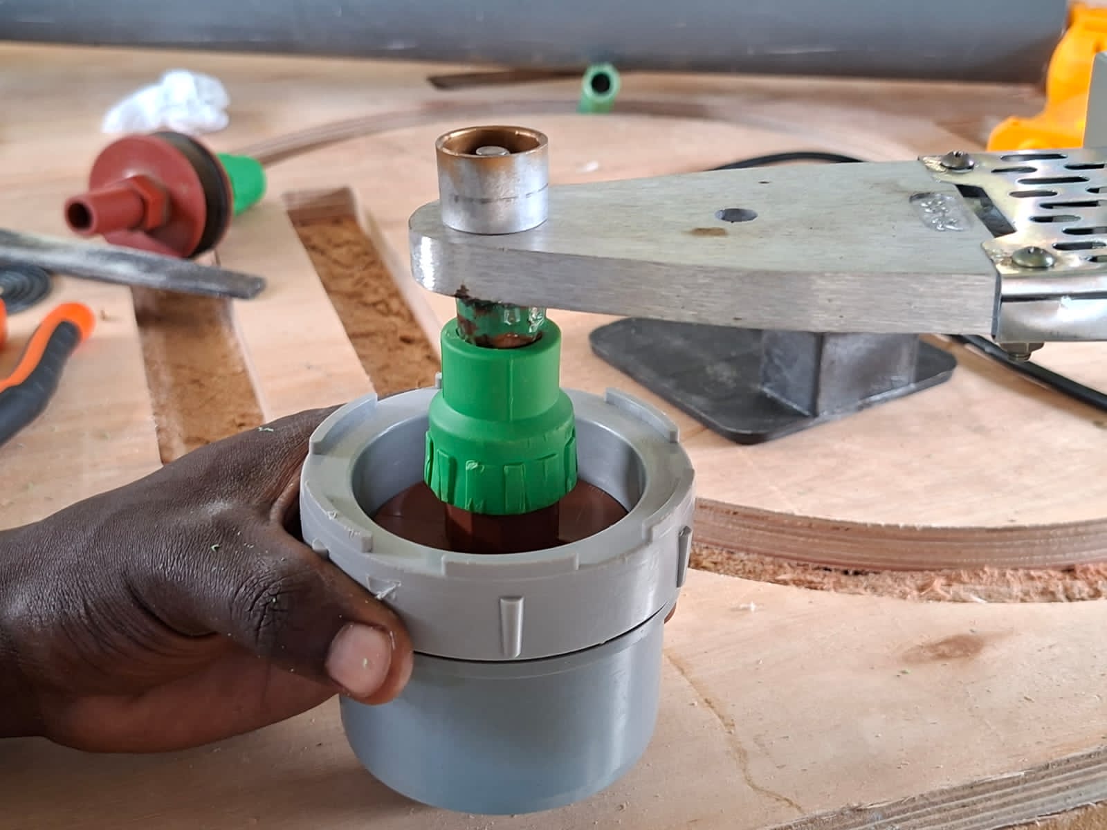
Mechanical system
The mechanical system includes:
- Pipe connections
- Filtration chambers
- Sensor holders
- Electronics enclosure
- Mounting components
- 3D-printed components
What processes were used?
The project used several Fab Academy processes. For each process, I documented both the process and what was made using it.
2D CAD Design → PCB and component layouts
2D CAD and electronic design tools were used to create:
- PCB layouts
- PCB traces
- Board outlines
- Component placement
- System layout drawings
The PCB design was prepared for digital fabrication and later milled.
3D CAD Modeling → Sensor Housing and Control Box
3D CAD modeling was used to design:
- Sensor housing
- Sensor mounting fixtures
- Control/electronics box
- Mechanical brackets
- Other custom mounting components
The CAD models allowed dimensions and component placement to be tested before fabrication.
Sensor Housing CAD
CAD model to be displayed here:

Control Box CAD
CAD model to be displayed here:

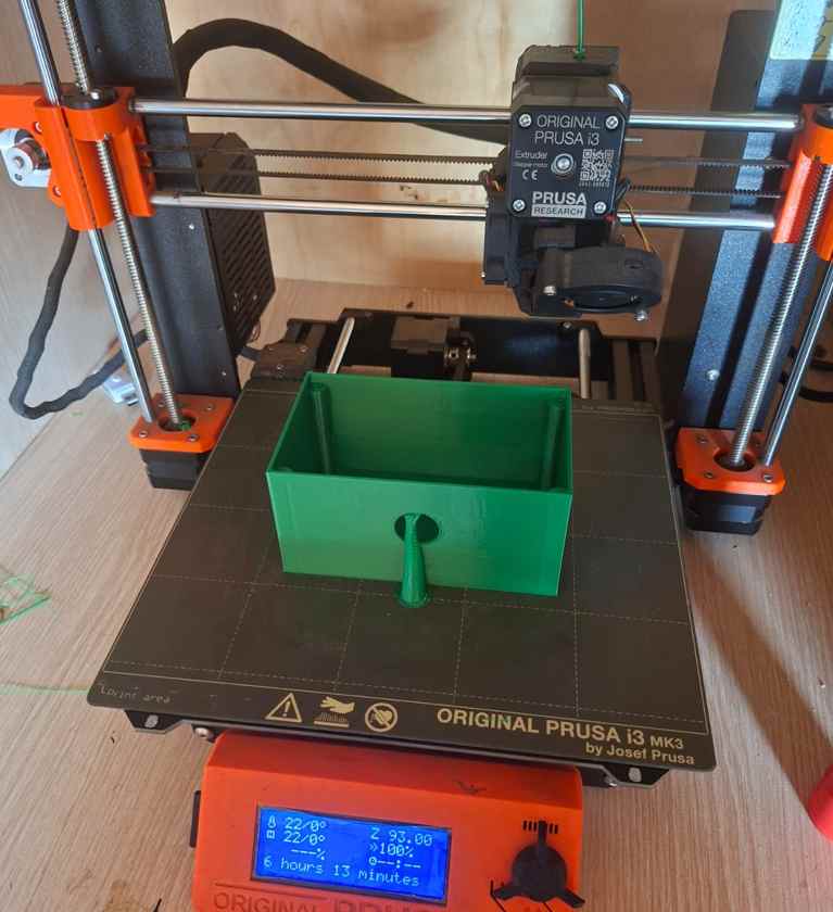
3D Printing → Custom Mechanical Parts
3D printing was used to manufacture custom mechanical components that could not easily be produced using standard hardware.
Examples include:
- Sensor holders
- Sensor housing components
- Mounting fixtures
- Electronics enclosure components
PCB Design → Custom Control PCB
A custom PCB was designed for the Water for Aduvan control system.
The PCB was designed to provide organized connections between:
- ESP32
- Sensors
- Pump
- Solenoid valves
- Power system
- Control electronics
PCB Fabrication → Milling the PCB
The PCB was fabricated using a digital milling process.
The fabrication workflow included:
- Preparing the PCB design.
- Checking the board outline and clearances.
- Exporting the required fabrication files.
- Preparing the milling toolpaths.
- Fixing the copper board to the milling machine.
- Milling the PCB traces.
- Milling the board outline.
- Cleaning the board.
- Inspecting the milled traces.
- Drilling/fabricating required holes.
- Testing electrical continuity.
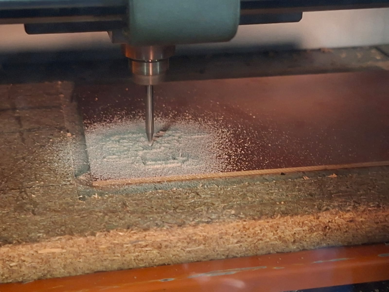
The milling process required careful adjustment of tool settings, trace widths, clearances, and board alignment to avoid damaged traces.
PCB Assembly → Soldering and Testing
After milling, electronic components were soldered onto the PCB.
The assembly process included:
- Cleaning the PCB
- Inspecting the milled traces
- Installing components
- Soldering components
- Checking solder joints
- Testing continuity
- Connecting sensors and actuators
- Power testing
- Testing communication with the ESP32
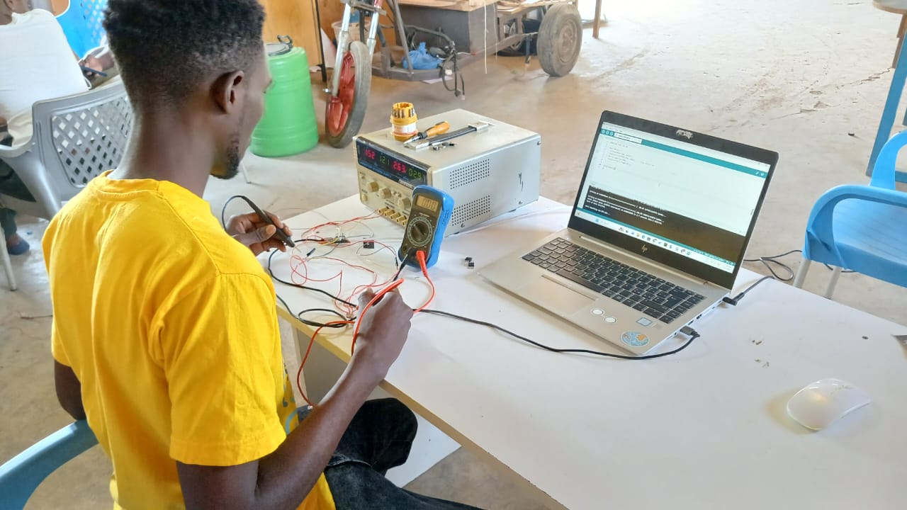
The completed PCB was then integrated into the control system.
Programming → ESP32 Firmware
The ESP32 was programmed to:
- Read sensor values
- Process sensor data
- Control pumps
- Control solenoid valves
- Monitor system status
- Send data through MQTT
- Support IoT dashboard monitoring
The firmware was tested incrementally during system integration.
IoT Development → Remote Monitoring Dashboard
An IoT dashboard was developed to display information from the water-treatment system.
The dashboard provides a way to monitor system information remotely and visualize sensor data.
Plumbing and System Integration → Complete Water System
The individual mechanical, electronic, and software subsystems were integrated into one working prototype.
The integration included:
- Connecting filtration stages
- Installing sensors
- Connecting the pump
- Installing solenoid valves
- Connecting the control electronics
- Connecting the power system
- Installing the custom PCB
- Connecting the IoT system
- Testing the complete water path
Sensor Calibration → Water Quality Monitoring
The turbidity and flow sensors were calibrated and tested before being used in the automated control system.
The calibration process involved comparing sensor readings under different operating conditions and adjusting the software interpretation of the readings.
What questions were answered?
The project investigated the following questions:
- Can a low-cost ESP32-based controller manage a water-treatment process?
- Can turbidity measurements be used for automated water-flow decisions?
- Can water-quality information be monitored remotely?
- Can digital fabrication be used to produce custom water-treatment components?
- Can locally available materials be incorporated into a modular water-treatment system?
- Can the system architecture be replicated for community-scale applications?
- What limitations need to be addressed before community deployment?
What worked?
The following parts of the prototype worked successfully:
- Turbidity monitoring provided useful water-quality feedback.
- The ESP32 successfully processed sensor information.
- Pump control worked.
- Solenoid-valve control worked.
- MQTT communication successfully transmitted system information.
- Dashboard visualization worked.
- The custom PCB was fabricated and assembled.
- The mechanical and electronic subsystems could be integrated.
- The modular architecture allowed individual components to be tested separately.
What did not work or needs improvement?
Several challenges were identified during development.
Turbidity calibration
The turbidity sensor required repeated calibration and testing to obtain consistent readings.
Flow measurement
Flow measurements were less stable at low flow rates and require further calibration.
Filtration speed
The filtration process was slower than desired. Future designs will investigate improved filtration media, flow paths, pump selection, and treatment stages.
Advanced treatment stages
Electrocoagulation and photocatalytic treatment are part of the future development roadmap and were not fully implemented in the current prototype.
How was it evaluated?
The prototype was evaluated through functional testing of the electronic, mechanical, software, and water-treatment subsystems.
| Evaluation Metric | Result |
|---|---|
| Water flow control | Pass |
| Sensor operation | Pass |
| Data transmission | Pass |
| Dashboard visualization | Pass |
| Turbidity monitoring | Pass |
| Automated decision making | Pass |
| Continuous system operation | Pass |
| Mechanical integration | Pass |
| PCB operation | Pass |
Water samples were compared before and after filtration to evaluate changes in turbidity.
Further laboratory water-quality testing is required before making claims about drinking-water safety or community deployment.
What are the implications?
Water for Aduvan demonstrates how digital fabrication, embedded electronics, sensing, automation, and IoT can be combined to develop locally manufacturable water-treatment technologies.
The project has potential implications for:
- Affordable water-treatment systems
- Community-level monitoring
- Local manufacturing
- Technical skills development
- Real-time water-quality monitoring
- Modular treatment systems
- Rural and peri-urban water infrastructure
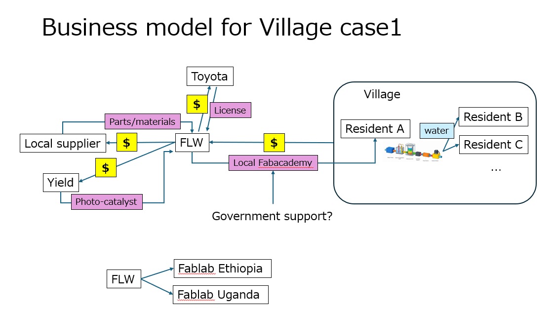
The project is aligned with UN Sustainable Development Goal 6: Clean Water and Sanitation.
Partnership and Future Development
Future development will focus on improving the treatment process and preparing the system for real-world testing.
Planned developments include:
- Integration of an electrocoagulation chamber
- Photocatalytic treatment
- Partnership with Toyota for further development
- Additional water-quality sensors
- TDS/conductivity monitoring
- Improved turbidity sensing
- Solar-powered operation
- Battery-powered portable operation
- Improved filtration speed
- Improved mechanical enclosure
- More robust PCB design
- OTA firmware updates
- Community pilot testing
- Deployment around communities in the Lake Victoria region
The future objective is to transform the prototype into a more robust, portable, energy-efficient, and maintainable water-treatment platform.
Use of AI and ChatGPT
Artificial intelligence tools, including ChatGPT, were used during development as a supporting tool.
ChatGPT was not treated as the author of the project. It was used for activities such as:
- Explaining technical concepts
- Troubleshooting programming errors
- Reviewing code logic
- Suggesting debugging approaches
- Explaining sensor behaviour
- Assisting with documentation structure
- Improving technical writing
- Generating initial code examples where applicable
Any code that was not originally written by me is identified as AI-assisted or sourced from the relevant reference.
ChatGPT prompts used
Examples of prompts used during development include:
“Help me write ESP32 code to read a turbidity sensor and control a solenoid valve based on the sensor reading.”
“Help me troubleshoot why the ESP32 ADC is reading 4095 from the turbidity sensor.”
“Explain how to connect an ESP32 to a turbidity sensor and flow sensor.”
“Help me debug the MQTT communication between the ESP32 and the IoT dashboard.”
“Explain how I can calibrate the turbidity sensor.”
“Help me improve this ESP32 code and explain the changes.”
“Help me document my Fab Academy final project.”
Where AI-generated code was incorporated into the project, the relevant project page should identify the code as ChatGPT-assisted and include the actual prompt used.
Design Files
All original design files used to fabricate the Water for Aduvan prototype should be provided below.
CAD Files
- Sensor Housing — STL
- Sensor Housing — STEP
- Control Box — STL
- Control Box — STEP
- Sediment_Holder
- 3D Printing Files, Sediment Holder
PCB Design Files
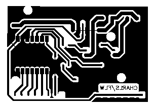
Manufacturing PCB Files
3D Printing Files
Source Code
Project Summary
Water for Aduvan combines water treatment, digital fabrication, electronics, embedded programming, sensing, automation, and IoT monitoring into one integrated prototype.
The project demonstrates the complete process from problem identification → concept development → CAD design → electronic design → PCB fabrication → programming → mechanical fabrication → system integration → testing → future development.
The project will continue beyond Fab Academy through further treatment development, partnership, testing, and potential community deployment.
License
Documentation and Creative Work
Unless otherwise stated, the original documentation, photographs, diagrams, CAD designs, PCB designs, illustrations, and other creative materials created for the Water for Aduvan project by Charles Otieno Wangara are licensed under the:
Creative Commons Attribution-NonCommercial-ShareAlike 4.0 International (CC BY-NC-SA 4.0)
This means that others may share and adapt this work for non-commercial purposes, provided that they:
- Give appropriate credit to Charles Otieno Wangara and the Water for Aduvan project.
- Provide a link to the CC BY-NC-SA 4.0 license.
- Indicate if changes were made.
- Distribute adaptations under the same license.
View the full CC BY-NC-SA 4.0 license
Software
The source code developed for the Water for Aduvan project is released under the MIT License, unless otherwise stated.
This includes original software such as:
- ESP32 firmware
- Sensor-control software
- MQTT communication
- IoT dashboard
- Backend services
- Frontend application
The MIT License permits others to use, copy, modify, merge, publish, distribute, sublicense, and sell copies of the software, provided that the original copyright and license notice are retained.
The software license does not change the license of the project documentation, CAD designs, photographs, or other creative materials.
Third-Party Materials
Third-party materials used or referenced in this project, including manufacturer datasheets, logos, external images, libraries, research papers, and other copyrighted materials, remain subject to their respective licenses and are not automatically covered by the licenses above.
© 2026 Charles Otieno Wangara — Water for Aduvan