8. Electronic Production
group assignment: • characterize the design rules for your in-house PCB production process
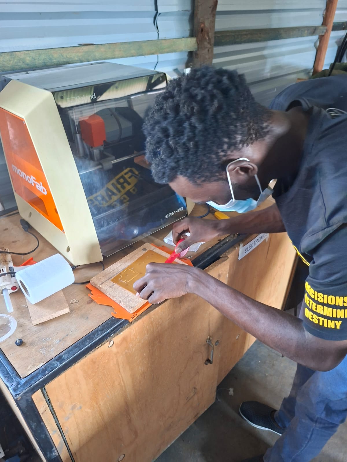
At fablabwinam we use. Roland Monofab SRM-20. Spindle speed goes up to 9300
• submit a PCB design to a board house
individual assignment: • make and test an embedded microcontroller system that you designed • extra credit: make it with another process
Refining my design in week 6
I updated my MCU from the through-hole XIAO ESP32 module 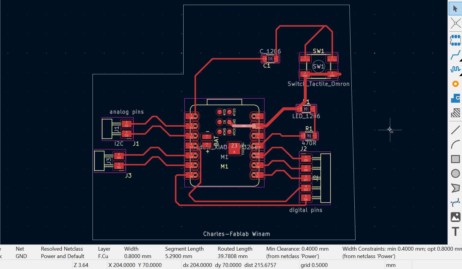 to the
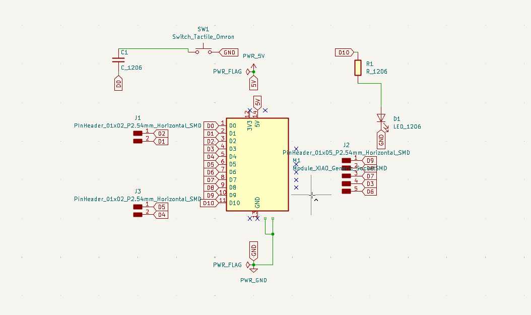
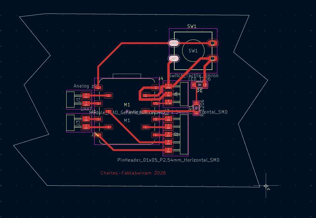
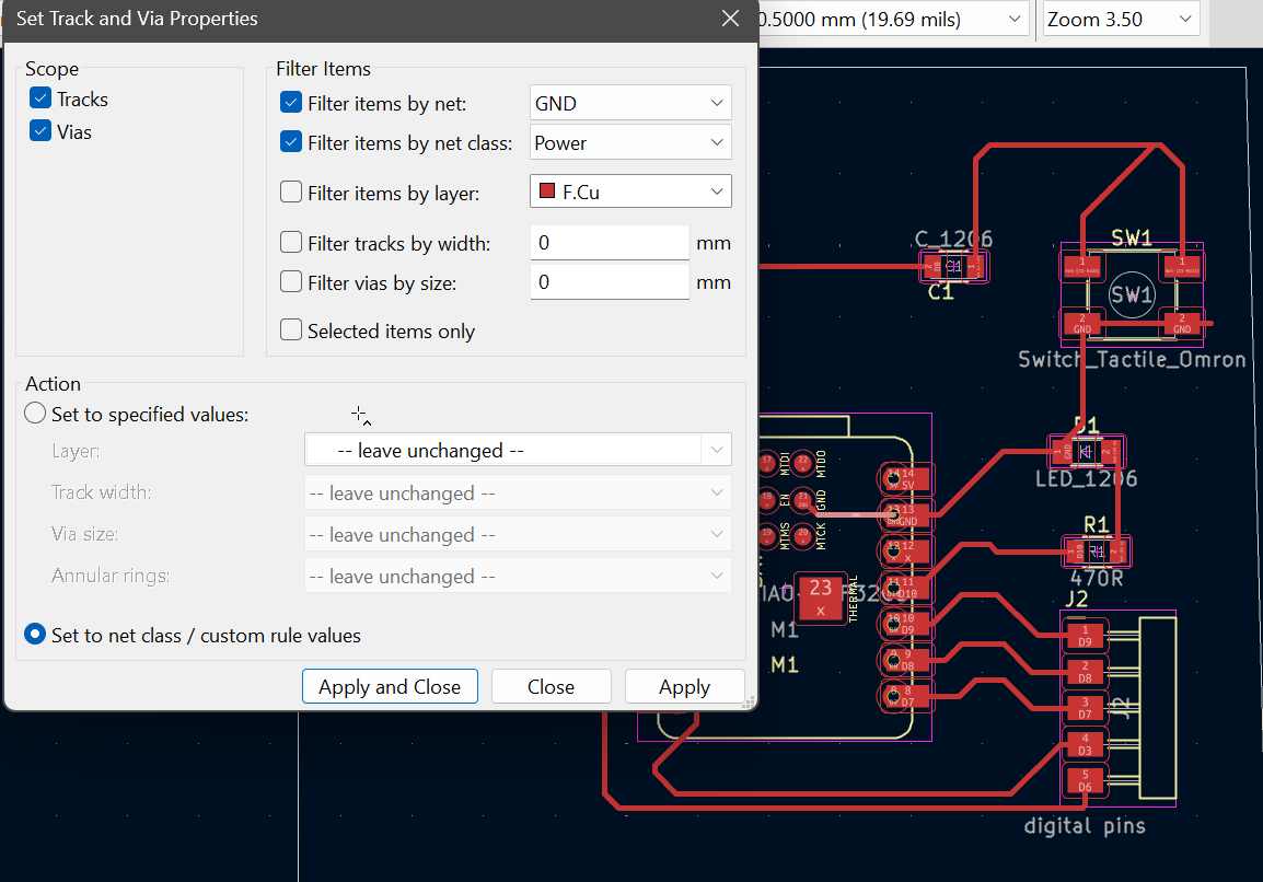
Module_XIAO_Generic_SocketSMD because I needed an SMD socket that allows easy reuse of the module instead of soldering it permanently. After making this change in the schematic, I updated the PCB editor and re-routed the board to match the new footprint. I also improved the power design by increasing the GND trace width to 0.8 mm so it can handle current better than thinner traces; to achieve this, I first changed the net class from Default to Power and then adjusted the width under the track and via properties, ensuring more stable and reliable power connections.
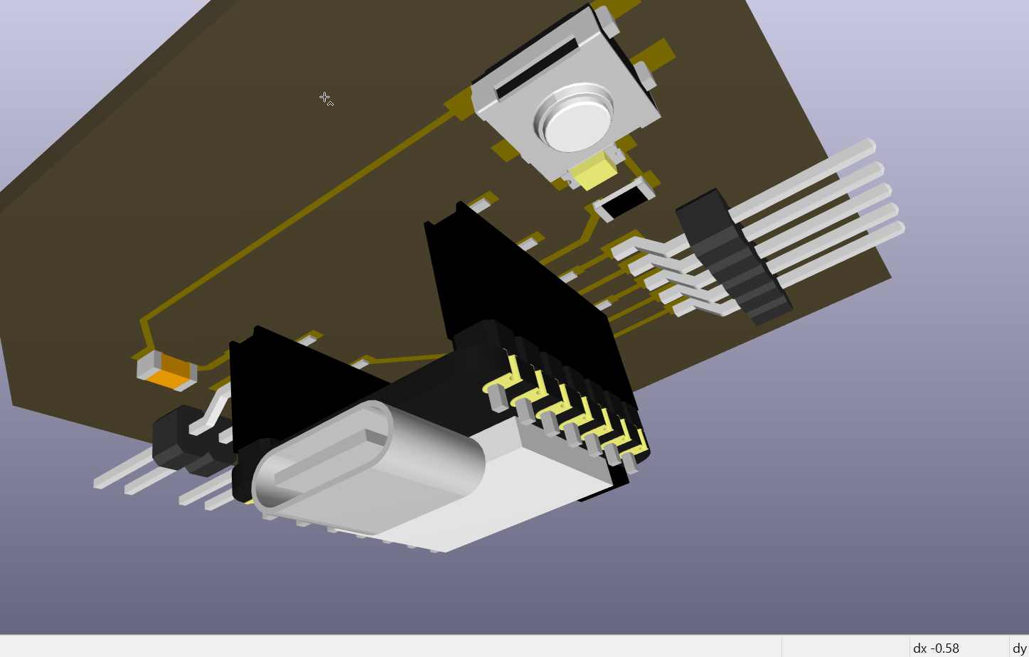
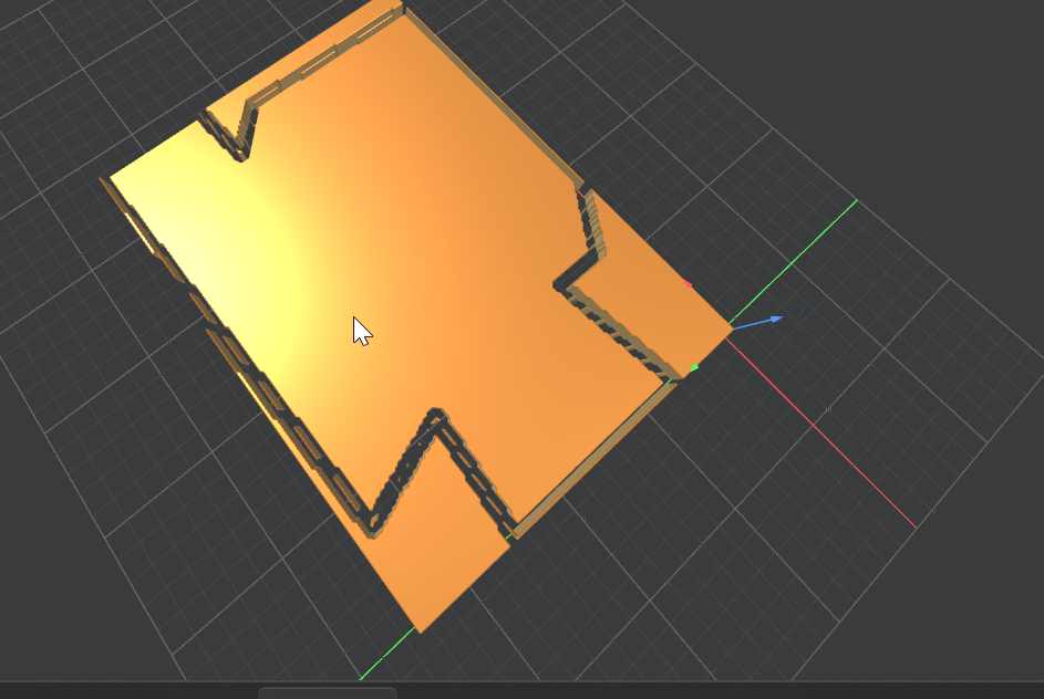
3D simulation for new design
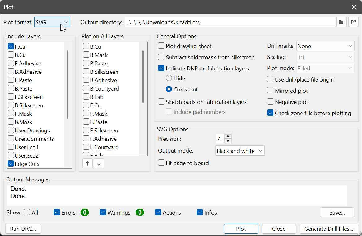
Ploting and Export SVG
under files, plot ensured i selected svg and not gerber, then selected F.Cu and Edge.Cut.and i secified my output directory to keep files organized.
Prepare to cut using CAM Modsproject
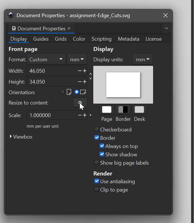
I used inksape to resize edgecuts and traces, since svg was exporting using the sheet size. From here i export as svg to mods
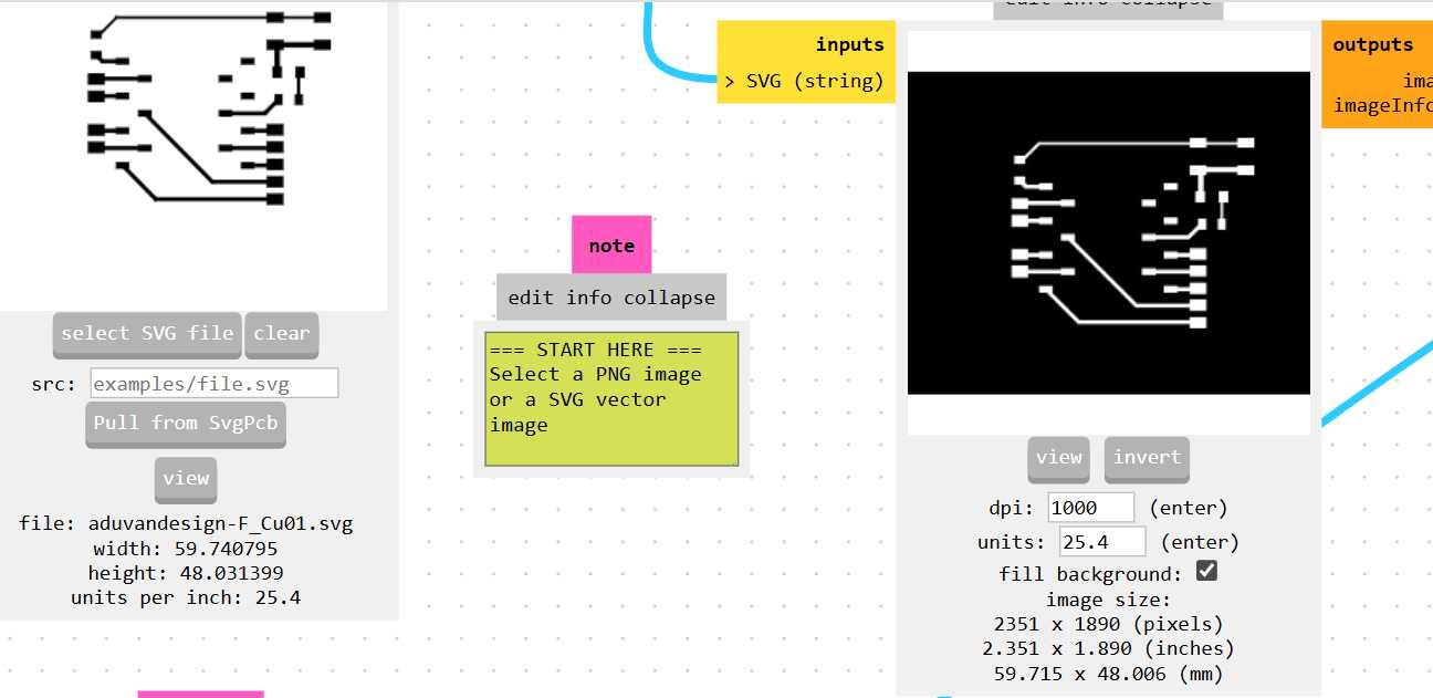
In MODS you have to invert to so that it removes unneccessary layers
For edge cutting, use 1/32 endmill under cut and for traces i use 1/64 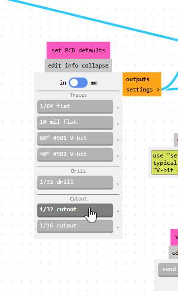
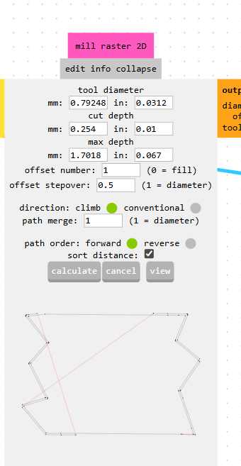
Cut Depth,tool diameter,maximum cut depth.. For traces i used this
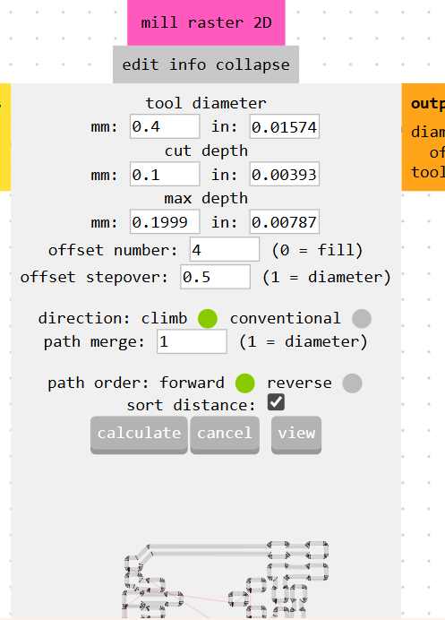
For edgecut i used this
After this i click calculate or go to home, then it downloads a rml file.
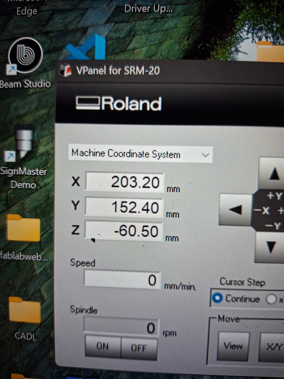
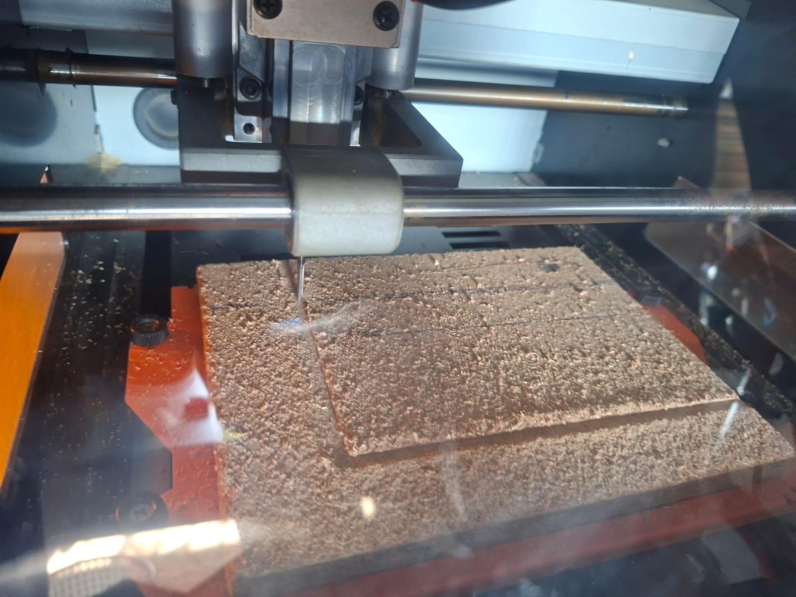
Vpanel and Cutting I used vpanle to control the machine. I used the xyz cordinates to set my origin. After installing bit, i set Z on the surface of the board, and x,y on the xy cordintates from where i want my cutting to begin from.
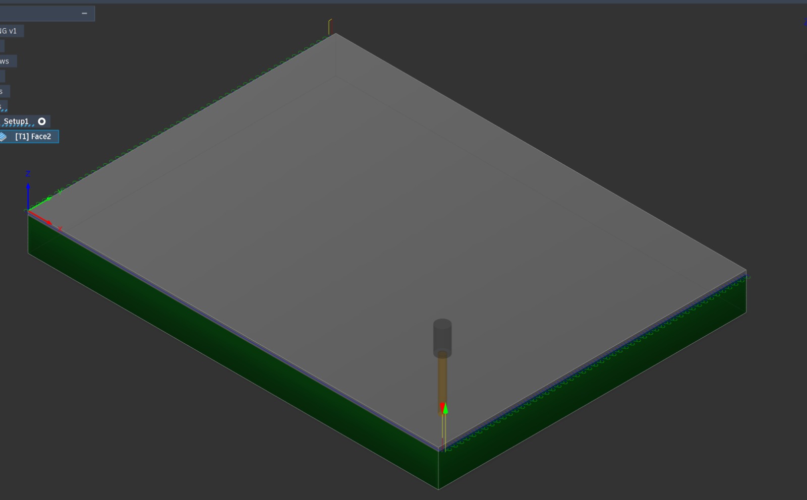
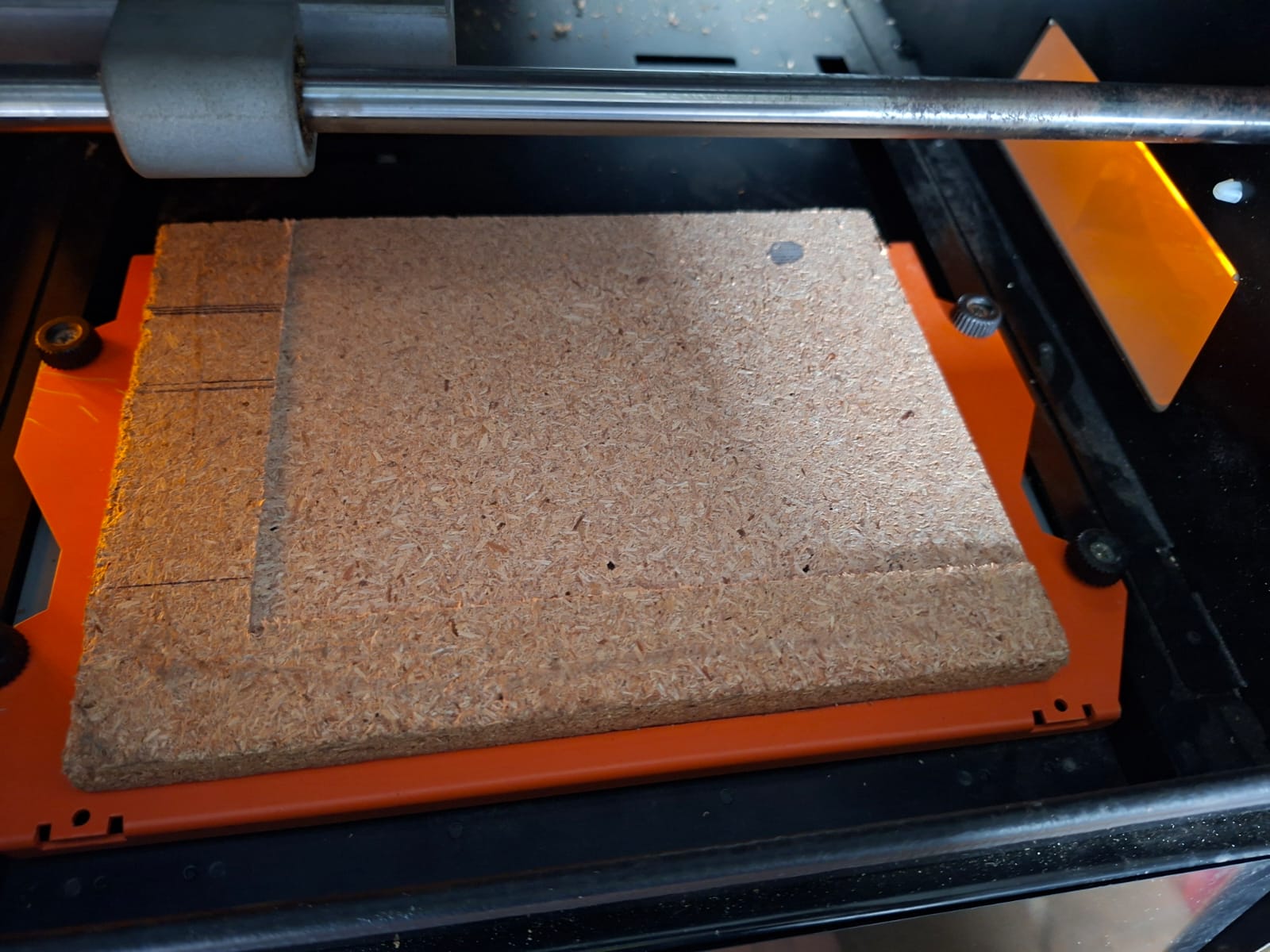
Surfacing To ensure a flat surface, I fixed an MDF board using double-sided tape. I used a 3.175 mm flat endmill single flute , then i modelled the spoil board in fusion with x 200mm and y 150mm
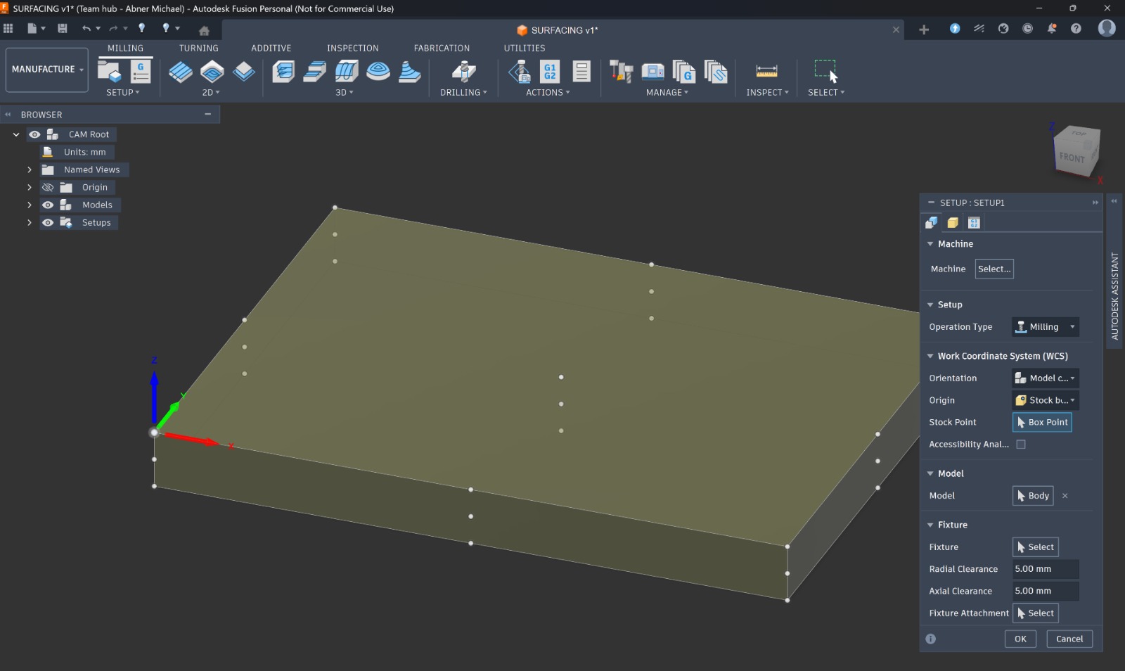
with a high stepover and created a surfacing toolpath in Fusion (1 mm depth) matching the board size. The machine milled the surface evenly until flat, after which I mounted the PCB with double-sided tape, ready for cutting.
I used the following settings
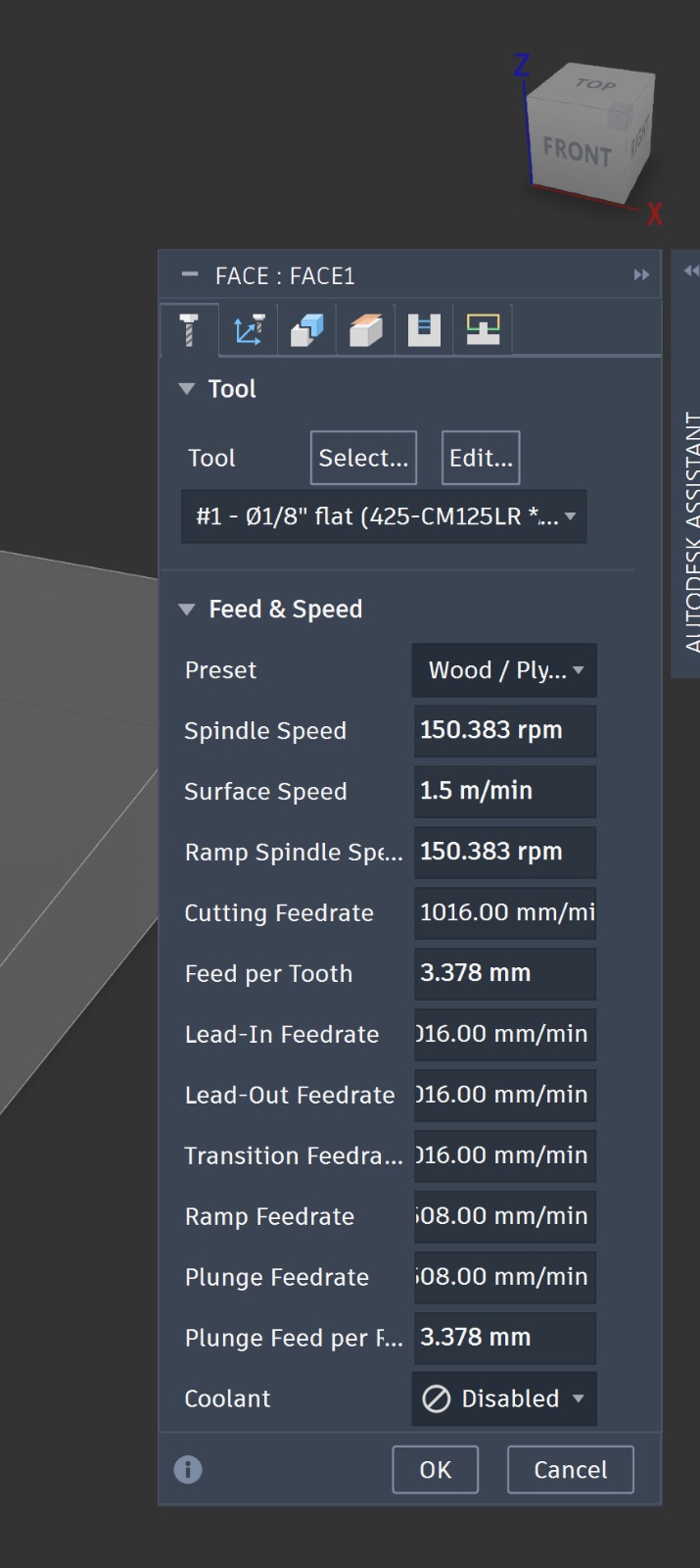
Select this tool
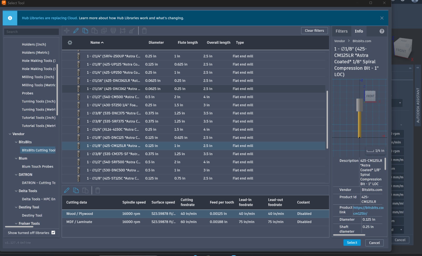
Using double sided tape,
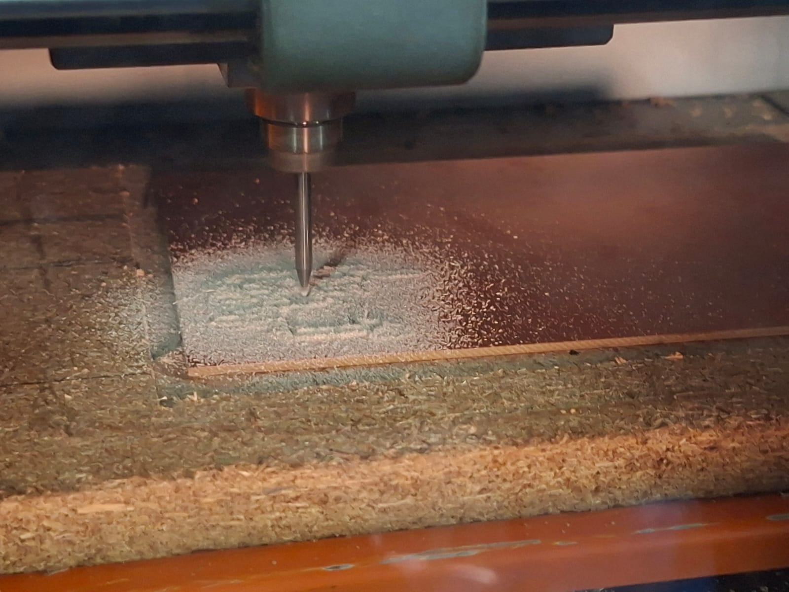
Cutting
Got this error while printing my first file 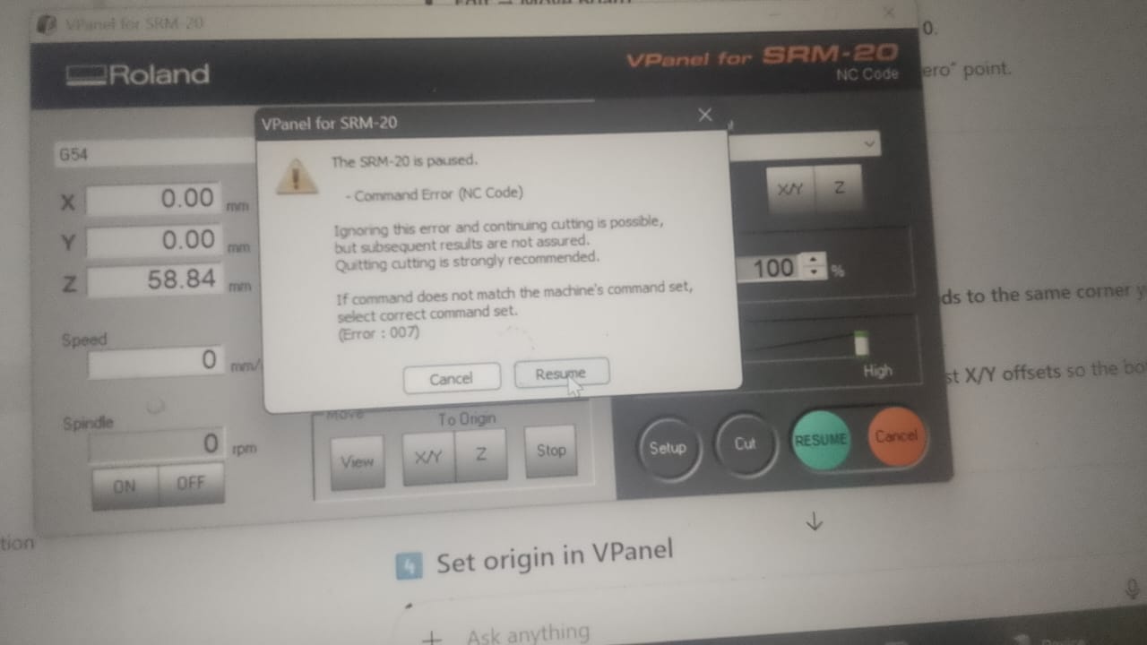 and realized it was a unit mismatch from mods.
During the milling process, I encountered several failures that helped me understand the importance of proper setup and careful handling.
and realized it was a unit mismatch from mods.
During the milling process, I encountered several failures that helped me understand the importance of proper setup and careful handling.
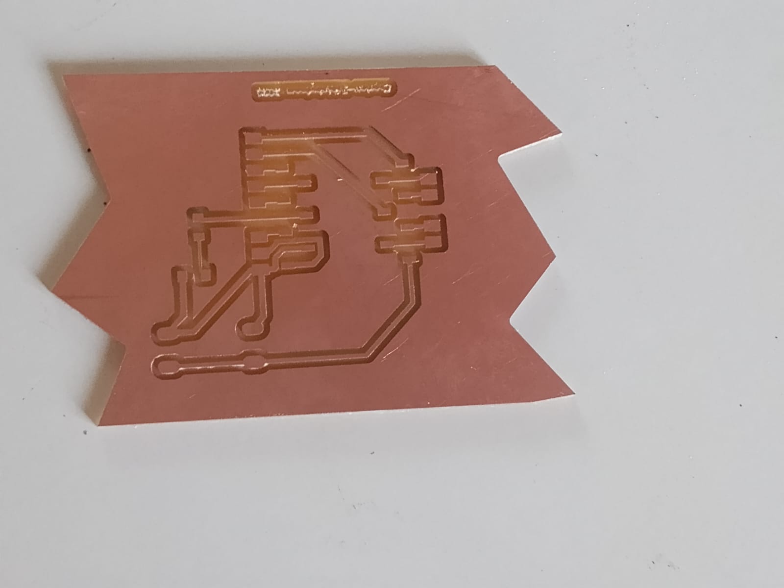
The issue was with the edge cuts going outside the intended board boundary due to a poorly defined outline. This caused inaccurate cuts and failures, highlighting the need to properly define the board edges and maintain enough clearance.
I also broke one milling bit unknowingly, which taught me the importance of handling bits with extreme care. Milling bits are very delicate—they should never be dropped or handled roughly, as even minor damage can affect performance or cause breakage.
Another mistake I made was related to machine movement and Z-axis control. Before moving the X and Y axes, the Z-axis must always be lifted to a safe height. I failed to do this, which contributed to errors during the process.
Additionally, several failures were caused by incorrect cut depth and homing settings:
In Mods, there is a default home position, which I repeatedly forgot to reset to X = 0 and Y = 0 before starting the job. For the cut depth, I initially relied on the default tool settings without customizing them in the “Edit → Info → Collapse” section. This led to incorrect cutting depths and poor results.
Soldering
Since my design has alternating pins, now i had to bend my pins to do surface mount soldring,
Testing continuity, Before and during soldering i was continoulsy testing contiuity using multimeter to see if there is unwanted connection. I used solder paste to ensure heating first and started with the pins,
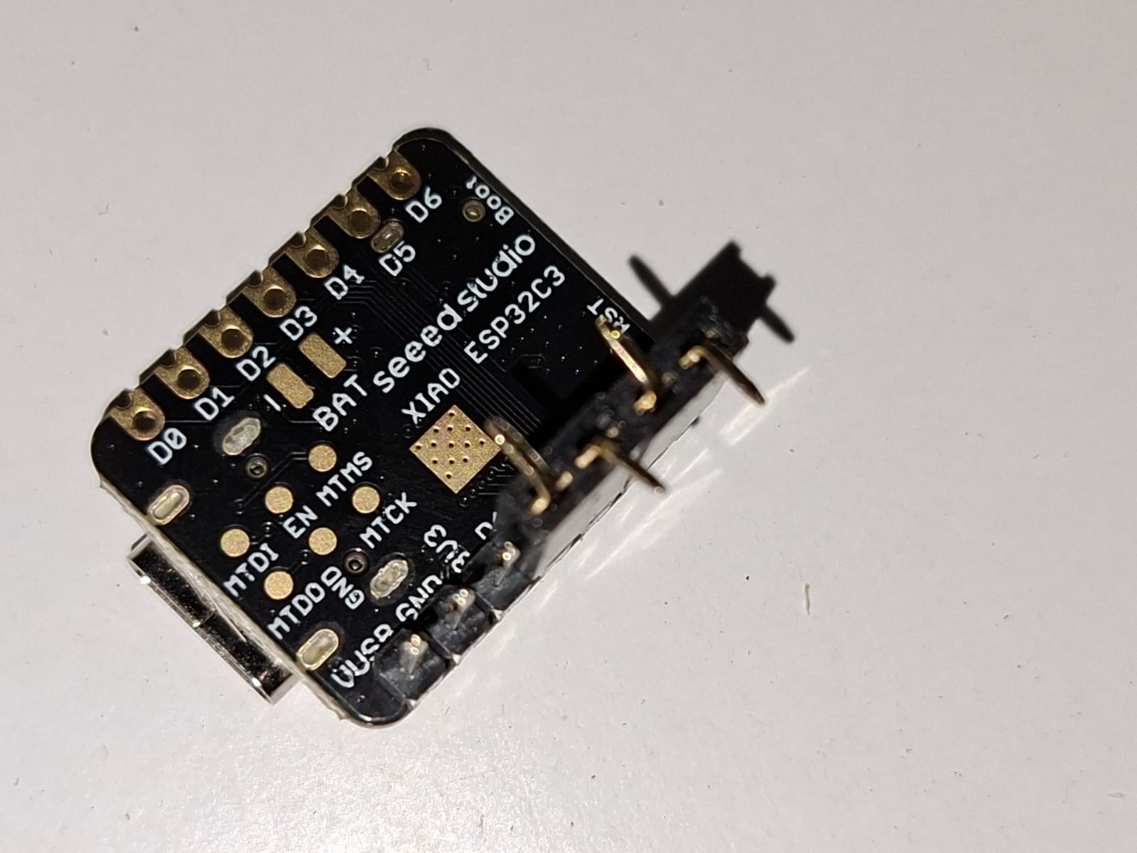
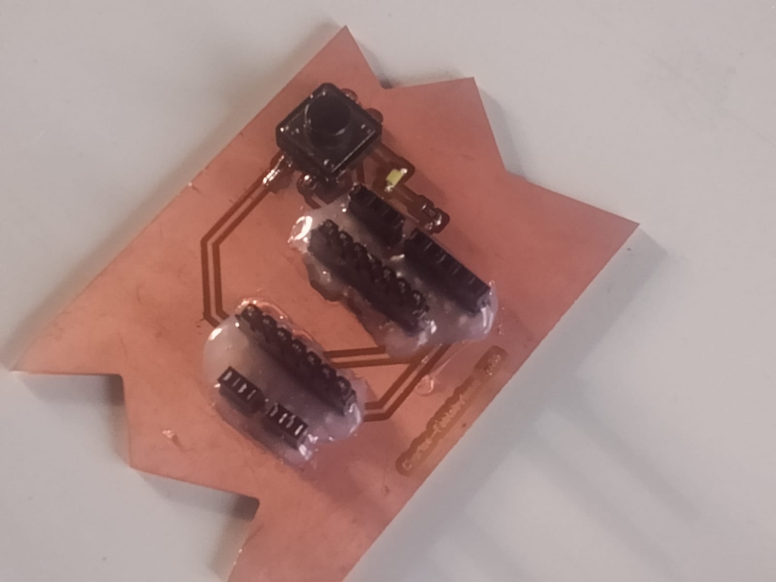
I secured the board using hot glue, to ensure the header pins are strong enough
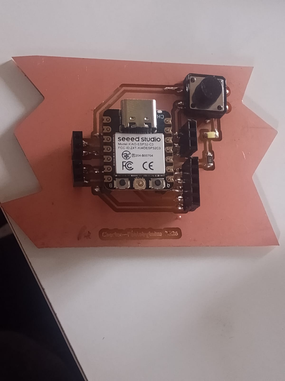
This is my complete soldered board, and ready to program it
Leaning Outcomes
At first while cutting always ensure the units are in mm in mods When working on an SRM Roland job in Mods, it is recommended to set the home position before saving the file. In the “Edit → Set Home” section, set X = 0 and Y = 0. Then, in the “Edit → Move to Origin (collapse)” settings, also ensure X = 0 and Y = 0, while leaving the Z value unchanged.
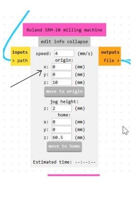
This ensures that the machine starts from a consistent origin point, helping maintain proper alignment and preventing unexpected offsets during milling.
## Design Files
Surfacing file used surface file_f3d format Edge_Cut gbr_FileFu_cut_File Edgcut rml fileTraces rml file