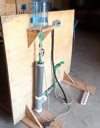
15. System Intergration
Fltraton module
Electronics
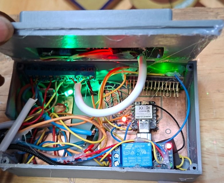
Realzed my electronc enclosure box, wrng and the ccut board was not neat and had to redesng evrythng and start a fresh.
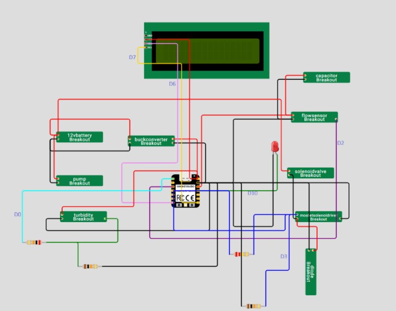
came up wth the dagram for my new crcut,components and enclosure.
Components needed.
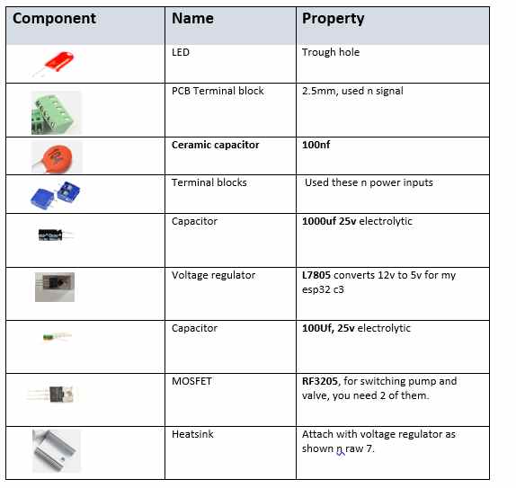
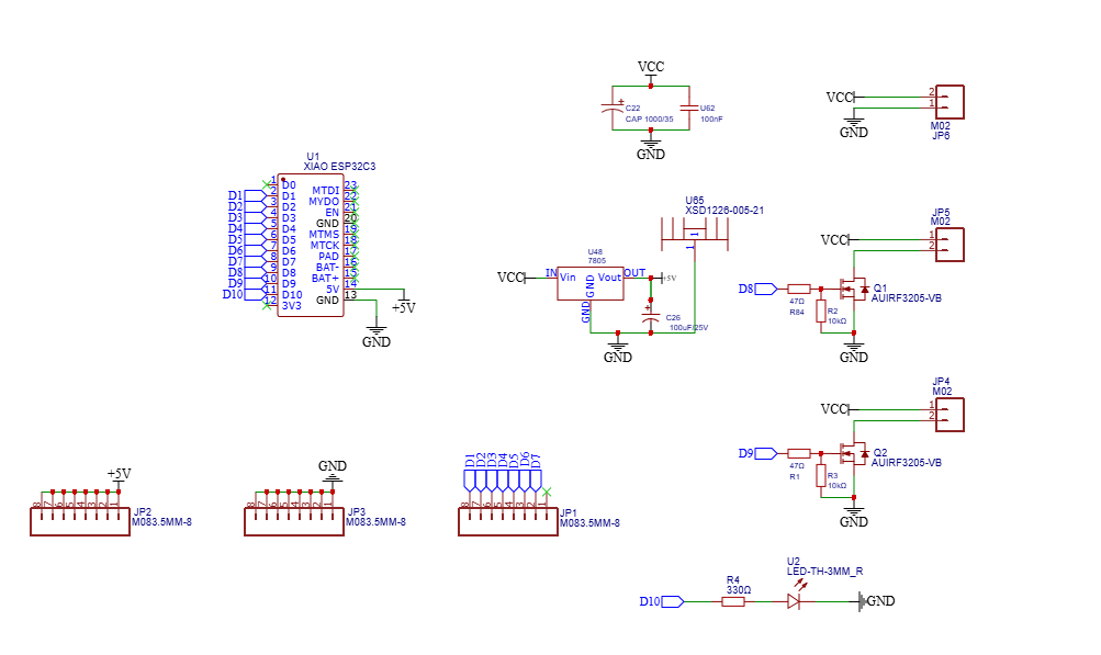
Above is my new circuit schematic, wth new components added.
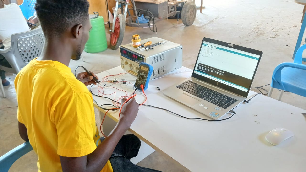
Testing without board
Electronics Testing and Troubleshooting Challenge Encountered During Hardware Testing
After assembling the control PCB, I uploaded the firmware to the Seeed Studio XIAO ESP32-C3 to test the pump and solenoid valve control. The microcontroller started correctly, the LCD displayed the startup message, and the program executed without errors. However, neither the pump nor the solenoid valve responded to the control signal.
Instead of assuming that the PCB or the software was faulty, I decided to troubleshoot the circuit step by step.
Step 1: Verify the ESP32 Output
I first confirmed that the ESP32 was producing the expected output signal. A simple test program was uploaded to toggle GPIO D8 continuously between HIGH and LOW.
Using a digital multimeter, I measured the voltage between D8 and ground.
Test Result D8 → GND 0–3.4 V alternating
This confirmed that the microcontroller and the firmware were operating correctly.
Step 2: Verify the Loads
To ensure that the problem was not caused by the pump or the solenoid valve, both devices were tested independently using the 12 V power supply.
Pump Test
The pump was connected directly to the 12 V supply.
Result: The pump operated normally.
Solenoid Valve Test
The solenoid valve was connected directly to the 12 V supply.
Result: The valve actuated correctly with an audible click.
This confirmed that both loads were functional.
Step 3: Verify the MOSFET Driver Circuit
I then focused on the MOSFET switching circuit.
The following measurements were taken while the ESP32 output was toggling.
Measurement Result
D8 → GND 0–3.4 V
Source → GND 0 V
Drain → GND 12 V
Pump (+) → GND 12 V
Pump (−) → GND 12 V
Since the drain remained at 12 V, the MOSFET was not switching the load.
Step 4: Checking PCB Connections
The next step was to inspect every connection around the MOSFET.
Continuity tests were performed between:
ESP32 D8 and the gate resistor
Gate resistor and MOSFET gate
MOSFET gate and pull-down resistor
Pull-down resistor and ground
The PCB traces were electrically continuous, so I began checking the actual component values.
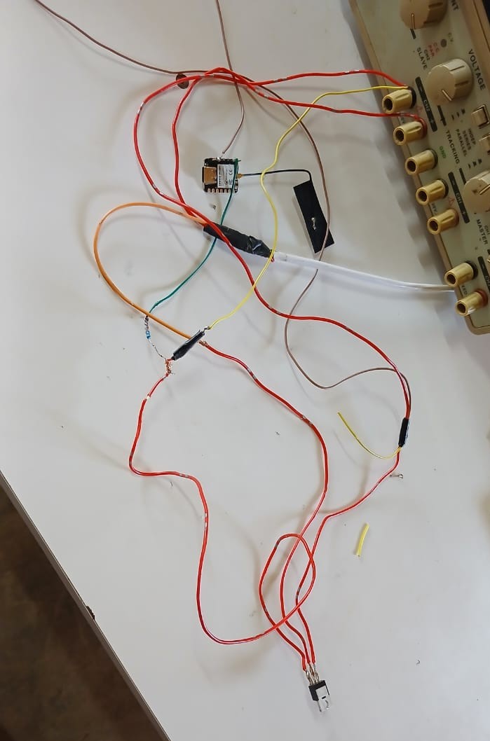
Step 5: Isolating the Circuit from the PCB
At this stage, I wanted to determine whether the problem was caused by the circuit design itself or by the assembled PCB. To do this, I rebuilt the MOSFET driver circuit outside the PCB using wires
The test circuit consisted of:
Seeed Studio XIAO ESP32-C3
IRLB4132 logic-level MOSFET
47 Ω gate resistor
10 kΩ gate pull-down resistor
12 V DC power supply
12 V DC pump
Solenoid valve
The same firmware that had been uploaded to the PCB was used without making any software changes.
Observation
When the circuit was wired externally:
The pump switched ON and OFF correctly.
The solenoid valve actuated correctly.
The MOSFET responded immediately to the ESP32 control signal.
The gate voltage alternated correctly between approximately 0 V and 3.3 V.
Conclusion
Since the exact same circuit operated correctly when assembled externally, I concluded that the schematic design, firmware, ESP32, MOSFET, pump and solenoid valve were all functioning properly. The problem had to be related to the assembled PCB rather than the circuit design.
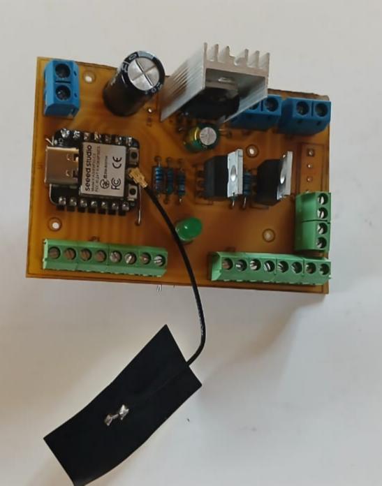
Step 6: Inspecting the Assembled PCB
After confirming that the circuit worked externally, I returned to the PCB and carefully inspected every component against the schematic. I checked the MOSFET orientation, continuity of the PCB traces, solder joints and the values of the resistors installed in the gate driver circuit.
During this inspection, I discovered that I had assembled the PCB with an incorrect resistor value. The design required a 47 Ω gate resistor together with a 10 kΩ pull-down resistor, but I had mistakenly installed a 470 Ω resistor in place of the 47 Ω resistor, and one of the required resistors had also been omitted during assembly.
After replacing the incorrect resistor with the correct 47 Ω resistor and installing the missing resistor, the MOSFET driver operated exactly as intended.
Final Verification
The PCB was tested again using the same firmware.
This time:
✔ The pump switched ON and OFF correctly.
✔ The solenoid valve operated correctly.
✔ The MOSFET responded reliably to the ESP32 GPIO output.
✔ The complete control PCB functioned without any further modifications.
Electronic Box