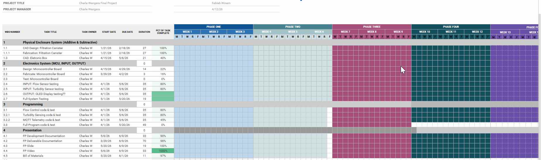
Skip to content

Project_Tracker

Access to safe and clean drinking water remains a major challenge in Kenya, where millions of people still lack reliable water services. In cities like Kisumu and many rural areas, communities depend on pump-based systems and natural water sources that are often not monitored, leading to water contamination with suspended particles, heavy metals, and other harmful substances, which increases health risks and inequality in access to safe water.

This project addresses the problem by developing a portable, modular water purification and control system that can be added to existing water sources without major infrastructure changes. It combines electrocoagulation, physical filtration, and real-time monitoring using turbidity and flow sensors, all controlled by a microcontroller, to ensure water only flows when it meets safety standards, while automated valves regulate distribution and a dashboard provides users with clear insights into water quality and system performance.

alt text

Gant Chart

alt text

Bill of Materials (BOM)

# Item Consumable (Y/N) Quantity Unit Cost (KES) Total Cost (KES) Use / Function
1 PVC Pipe 3” (13 feet) Y 1 500 500 Main water flow channel
2 PVC Plug 3” Y 3 150 450 Sealing pipe ends
3 PPR Welding Machine N 1 2500 2500 Joining plastic pipes
4 Male Adapter 1/2” Y 8 50 400 Pipe connection interface
5 Tank Connector 1/2” Y 8 300 2400 Connecting tank to piping
6 Plain Elbow 1/2” Y 8 30 240 Changing flow direction
7 Solfix Gum Y 1 200 200 Sealing and bonding joints
8 Female Adapter 1/2” Y 4 50 200 Pipe-to-device connection
9 T-Connector Y 1 200 200 Splitting water flow
10 Flow Sensor Y 2 820 1640 Measuring water flow rate
11 Solenoid Valve Y 2 1000 2000 Automatic water control (on/off)
-------------------------- ------------------ ---------- ------------------ ------------------ ----------------------------------------
TOTAL 7090 KES

Physical Components and Fabrication

To make the project more fabrication-friendly and reduce reliance on 3D printing, the design focuses on custom-designing only the inlet and outlet. The filter itself can be any container of preferred size. This approach ensures easy maintenance, such as replacing charcoal, pebbles, or other filter media alt text To ensure continuous water availability during system maintenance, a water storage unit should be incorporated. The disinfection chamber must be able to supply water to users even while maintenance is ongoing.

For easier maintenance of the electrochemical (EC) chamber, it is recommended to place it after the filtration unit and turbidity sensor. Additionally, a storage unit on top of the EC chamber is suggested to facilitate operation and maintenance.

alt text

alt text

alt text

alt text

alt textalt text

tested the 3” waste pipe to check if the diameter fits with alt text

Later introduced the polygons shapes to have the sieve shapes

alt text

Sediment holder..

file

Pump

alt text

The project requires a 24 V DC self-priming diaphragm pump because the system needs to draw water from a tank without being submerged and still maintain consistent pressure for controlled delivery. The pump operates at about 50–60 PSI, which is sufficient to meet the solenoid valve’s minimum opening pressure requirement of about 3 PSI (0.02 MPa), ensuring the valve can open and close reliably, and it can handle flow rates within the YF-S201 flow sensor range of 1–30 L/min, allowing accurate measurement of water flow through pulse signals. The pump is also selected with 1/2 inch inlet and outlet ports to match the system piping, ensuring proper compatibility, reducing pressure loss, and allowing smooth water transfer without the need for adapters or flow restriction, making it efficient for the entire system.

Flow Sensor

alt text

Flow Rate: 0.00 L/min
Flow Rate: 0.27 L/min
Flow Rate: 0.67 L/min
Flow Rate: 0.93 L/min
Flow Rate: 1.07 L/min
Flow Rate: 0.93 L/min
Flow Rate: 1.07 L/min

I tested the sensor using xiao esp 32-c3, and connected with MQTT, and got the followng readings:

alt text

#include <WiFi.h>
#include <PubSubClient.h>

// WiFi
const char* ssid = "MT";
const char* password = "#@Innovate";

// MQTT
const char* mqtt_server = "broker.emqx.io";

WiFiClient espClient;
PubSubClient client(espClient);

// Flow sensor
const int flowPin = D2; // D2 (change if needed)
volatile int pulseCount = 0;

float flowRate = 0.0;
float totalLiters = 0.0;

unsigned long previousMillis = 0;

// Interrupt
void IRAM_ATTR pulseCounter() {
  pulseCount++;
}

// Connect WiFi
void setup_wifi() {
  delay(10);
  WiFi.begin(ssid, password);

  while (WiFi.status() != WL_CONNECTED) {
    delay(500);
    Serial.print(".");
  }

  Serial.println("\nWiFi connected");
}

// Reconnect MQTT
void reconnect() {
  while (!client.connected()) {
    if (client.connect("ESP32FlowClient")) {
      Serial.println("MQTT connected");
    } else {
      delay(2000);
    }
  }
}

void setup() {
  Serial.begin(115200);

  pinMode(flowPin, INPUT_PULLUP);
  attachInterrupt(digitalPinToInterrupt(flowPin), pulseCounter, FALLING);

  setup_wifi();
  client.setServer(mqtt_server, 1883);
}

void loop() {
  if (!client.connected()) reconnect();
  client.loop();

  unsigned long currentMillis = millis();

  if (currentMillis - previousMillis >= 1000) { // every 1 sec
    previousMillis = currentMillis;

    // Calculate flow rate (L/min)
    flowRate = pulseCount / 7.5;

    // Convert to liters per second and accumulate
    float litersThisSecond = flowRate / 60.0;
    totalLiters += litersThisSecond;

    pulseCount = 0;

    // Convert to string
    char flowMsg[20];
    char totalMsg[20];

    sprintf(flowMsg, "%.2f", flowRate);
    sprintf(totalMsg, "%.2f", totalLiters);

    // Publish to MQTT
    client.publish("water/flow", flowMsg);
    client.publish("water/total", totalMsg);

    // Debug
    Serial.print("Flow: ");
    Serial.print(flowRate);
    Serial.print(" L/min | Total: ");
    Serial.println(totalLiters);
  }
}

NC Solenoid valve alt text

The project uses a 24 V DC solenoid valve with 1/2 inch ports that remains normally closed and only opens when 24 V is applied. It is chosen to match the 1/2 inch piping system, ensuring smooth integration without flow restriction, and it operates effectively with the pump’s 50–60 PSI pressure to allow controlled water movement through the system. The valve is controlled based on sensor inputs such as turbidity and flow rate from the YF-S201 sensor (1–30 L/min), allowing it to open or close depending on water quality or abnormal conditions, and it provides a safe fail-state by automatically closing and stopping water flow in case of power loss or system failure.

Exsiting filters

alt text

Filtration Module

My filtration module uses 1/2 inch inlets and oultets pvc pipes and PVC pipe 3” as the main catriege

V = π r² h

r = d / 2 = 0.04445 m

h = 400 mm = 0.4 m

V ≈ 0.00248 m³

Litres

V = 0.00248 × 1000

V ≈ 2.48 Liters

alt text To ensure proper fitting and sealing of the components, heat shrink tubing was used to secure and slightly reduce the diameter of the 3-inch plugs, allowing them to fit correctly into the designated connectors. This method also improves grip and provides a tighter, more reliable seal alt text

To achieve a proper fit within the system, the longer leg of the connector was cut using a hacksaw. This modification was necessary to reduce the length of the connector so that it could fit inside the designated pipe and align correctly with the rest of the assembly. By shortening the connector, it ensured a better fit, improved alignment, and allowed for a more compact and efficient installation within the system.
alt text

alt text

After assembling and modifying the connector, a clamp was used to hold the joint firmly in place while it hardened. This ensured that the connection remained tightly secured and properly aligned during the curing process. The use of the clamp improved the strength of the joint, reduced the risk of leaks, and resulted in a more stable and durable connection within the system. alt text

The pipe connections were then assembled using a PPR (Polypropylene Random) welding machine, which was used to heat and fuse the connectors to the male adapters. This process ensures a strong, leak-proof joint that can withstand pressure within the system.

alt text

Sensors

Turbidity Sensor Tested alt text

The project uses the LGZD Sensor V1.1 turbidity sensor, powered at 5 V DC with a current consumption of up to 30 mA, making it suitable for direct connection to a microcontroller system. It measures water clarity by providing either an analog output (0–4.5 V) or a digital signal (0–5 V), with a fast response time of less than 500 ms, allowing the system to quickly detect changes in water quality. This sensor is chosen because it enables real-time monitoring of turbidity levels, so the system can automatically trigger actions such as activating the solenoid valve to stop or allow flow and controlling the pump, ensuring only clean water passes through the system while maintaining reliable and responsive automated operation.

const int turbidityPin = A0;

float V_clean = 2.77;
float V_dirty = 0.90;

int getAverage() {
  int sum = 0;
  for (int i = 0; i < 20; i++) {
    sum += analogRead(turbidityPin);
    delay(5);
  }
  return sum / 20;
}

void setup() {
  Serial.begin(115200);
  Serial.println("=== TURBIDITY MONITOR ===");
}

void loop() {
  int raw = getAverage();
  float voltage = raw * (3.3 / 4095.0);

  float turbidity = ((V_clean - voltage) / (V_clean - V_dirty)) * 100.0;

  // Clamp values
  if (turbidity < 0) turbidity = 0;
  if (turbidity > 100) turbidity = 100;

  // Classification
  String status;
  if (turbidity < 20) {
    status = "CLEAN 💧";
  } 
  else if (turbidity < 50) {
    status = "SLIGHTLY DIRTY 🌫️";
  } 
  else if (turbidity < 80) {
    status = "DIRTY 🟤";
  } 
  else {
    status = "VERY DIRTY 🚫";
  }

  // Print everything nicely
  Serial.print("Raw: ");
  Serial.print(raw);

  Serial.print(" | Voltage: ");
  Serial.print(voltage, 2);

  Serial.print(" V | Turbidity: ");
  Serial.print(turbidity, 1);
  Serial.print(" %");

  Serial.print(" | Status: ");
  Serial.println(status);

  delay(1000);
}

Results

SEN0189  Sensor  with Xiao Esp32-C3

New sensor readings
clean water 
Raw: 3435 Voltage: 2.77 V
Raw: 3438  Voltage: 2.77 V
Raw: 3432  Voltage: 2.77 V
Raw: 3434  Voltage: 2.77 V
Raw: 3432  Voltage: 2.77 V
Raw: 3422  Voltage: 2.76 V


Dirty Water
Raw: 1176  Voltage: 0.95 V
Raw: 1163  Voltage: 0.94 V
Raw: 1161  Voltage: 0.94 V
Raw: 1199  Voltage: 0.97 V
Raw: 1126  Voltage: 0.91 V
Raw: 1097  Voltage: 0.88 V
Raw: 1095  Voltage: 0.88 V
Raw: 1070  Voltage: 0.86 V
Raw: 1069  Voltage: 0.86 V

My averages
 float V_clean = 2.77;
float V_dirty = 0.90;

with very consistent readings now with new sensor

old sensor readings

Clean Water
Raw: 2029  Voltage: 1.64 V
Raw: 2030  Voltage: 1.64 V
Raw: 2037  Voltage: 1.64 V
Raw: 2041  Voltage: 1.64 V
Raw: 2039  Voltage: 1.64 V
Raw: 2040  Voltage: 1.64 V
Raw: 2044  Voltage: 1.65 V
Raw: 2043  Voltage: 1.65 V

Average Raw Value: 2037.6
Average Voltage: 1.643 V

dirty Water
Raw: 2139  Voltage: 1.72 V
Raw: 2141  Voltage: 1.73 V
Raw: 2151  Voltage: 1.73 V
Raw: 2153  Voltage: 1.74 V
Raw: 2152  Voltage: 1.73 V
Raw: 2154  Voltage: 1.74 V
Raw: 2152  Voltage: 1.73 V
Raw: 2166  Voltage: 1.75 V

Average Raw Value: 2150.27
Average Voltage: 1.733 V

Circuit Design and Programming Draft circuit

Am going to use Xiao ESP32C3 as my MCU, and to ensure I dont connet my pump directly to the controller i decided to use relays,

alt text