12. Mechanical Design
group assignment: • design a machine that includes mechanism+actuation+automation+function+user interface • build the mechanical parts and operate it manually • document the group project and your individual contribution Group Assignment
Hello-Hello Conveyor Machine
Project Overview
At the beginning of this assignment, I was not fully sure what to build. My initial idea was to design a small conveyor system that could be used at Fablab Winam for a future microfactory setup (bamboo and sisal processing).
After group discussions, we agreed to build a “Hello-Hello Machine” — a communication system between different Fab Labs. The idea was that one machine could send a physical message to another lab in real time.
My contribution was designing and building a conveyor-based mechanism that can move a message carrier and respond to remote commands sent through MQTT.
In my case, the machine is located at Fablab Winam and can be controlled from Skylab (Ethiopia) during testing. Was not sure about what to build, and decided to build a Hello-Hello machine, that we use to communicate accross our hubs.
I started with an idea to build a machine that cn be used at falab winam as, a small conveyer for microfactory processing.
And as a group we decided to make machines that can communicate together, my machine is able to send a message to Skylab from winam kisumu....
System Idea (Machine Concept)
The system is made of three main parts:
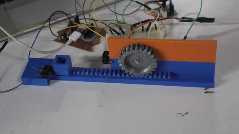
- Mechanical System Rack and pinion conveyor system Stepper motor for controlled movement Limit switches for safety and direction control
- Control System ESP32-C3 microcontroller Motor driver (ULN2003 for stepper) Buzzer feedback system
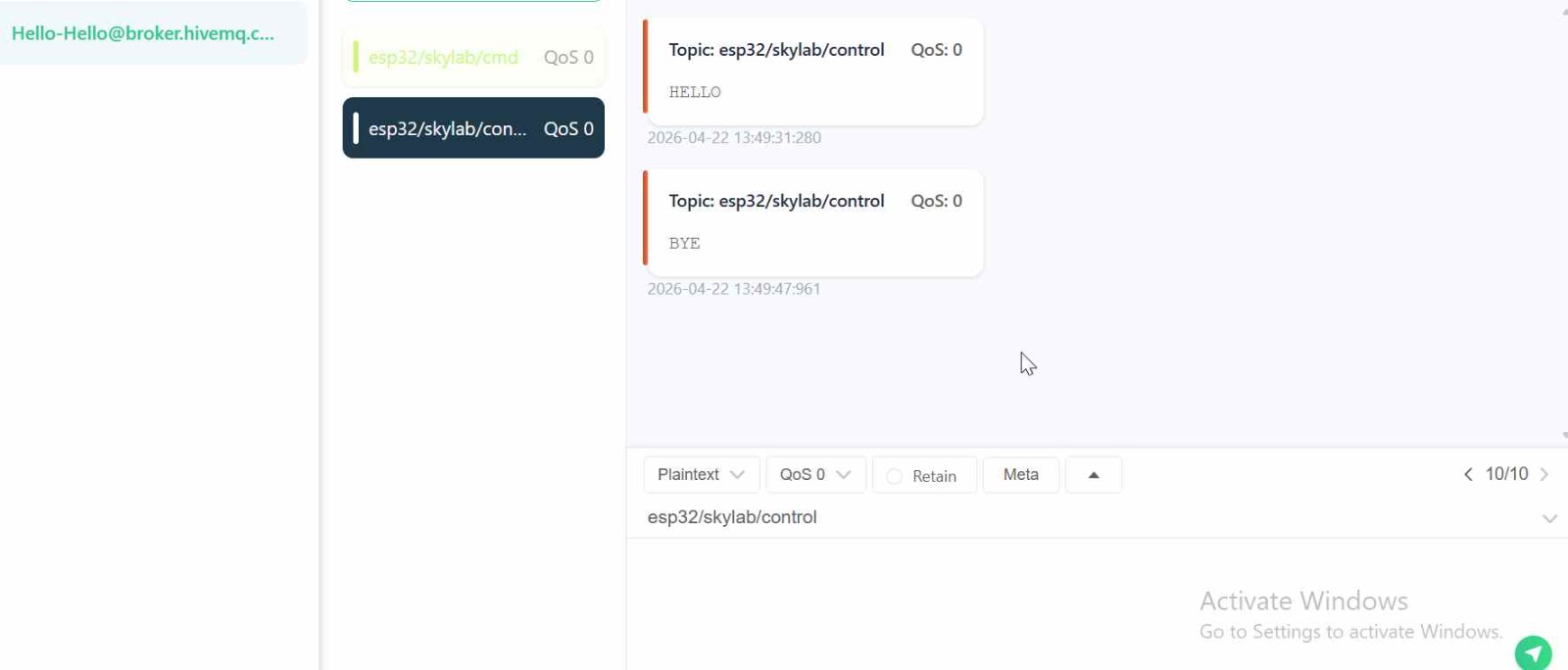
- Communication System MQTT over WiFi Remote control messages (“HELLO”, “BYE”, “STOP”)
System Flow
MQTT Command (Skylab / Remote User) ↓ ESP32-C3 ↓ Motor Control Logic ↓ Stepper Motor (28BYJ-48) ↓ Rack & Pinion Movement System ↓ Message moves between zones
Mechanical Design Process
Ideation using card board
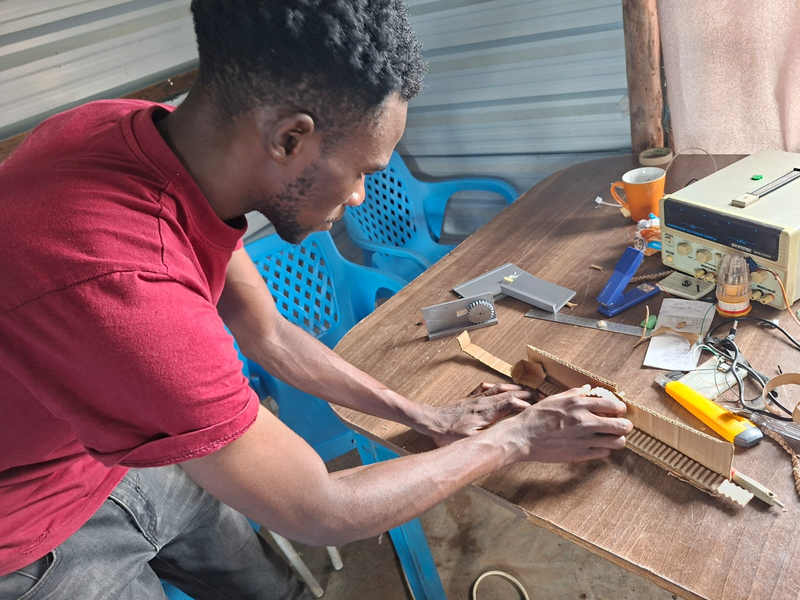
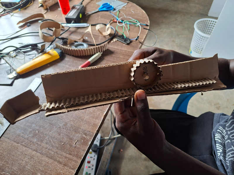
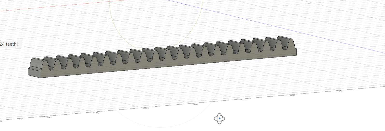
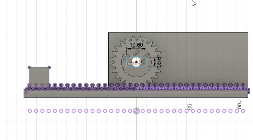
I watched rack and pinion from youtube rack and pinion then modified it to fit our machine.
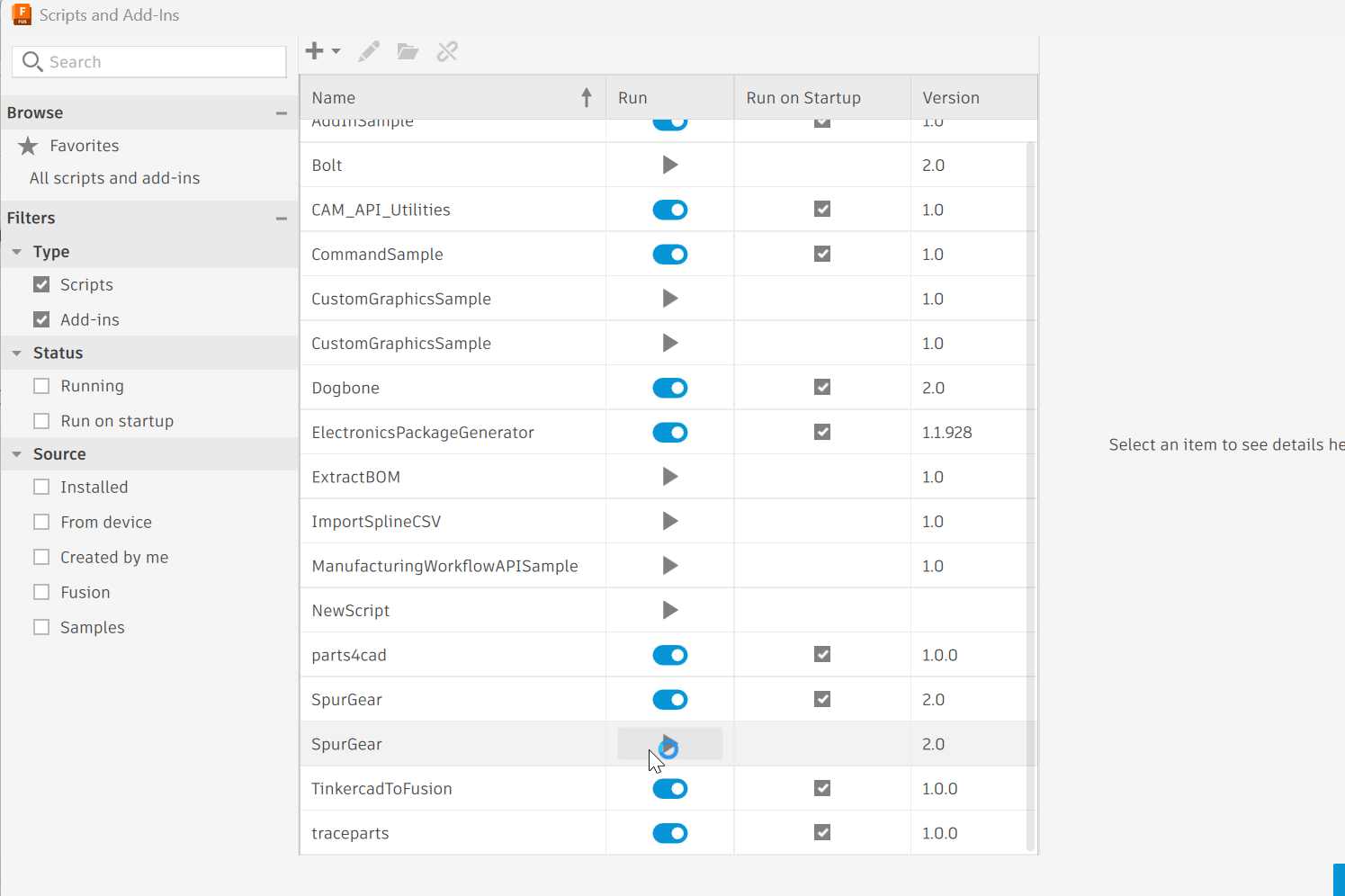
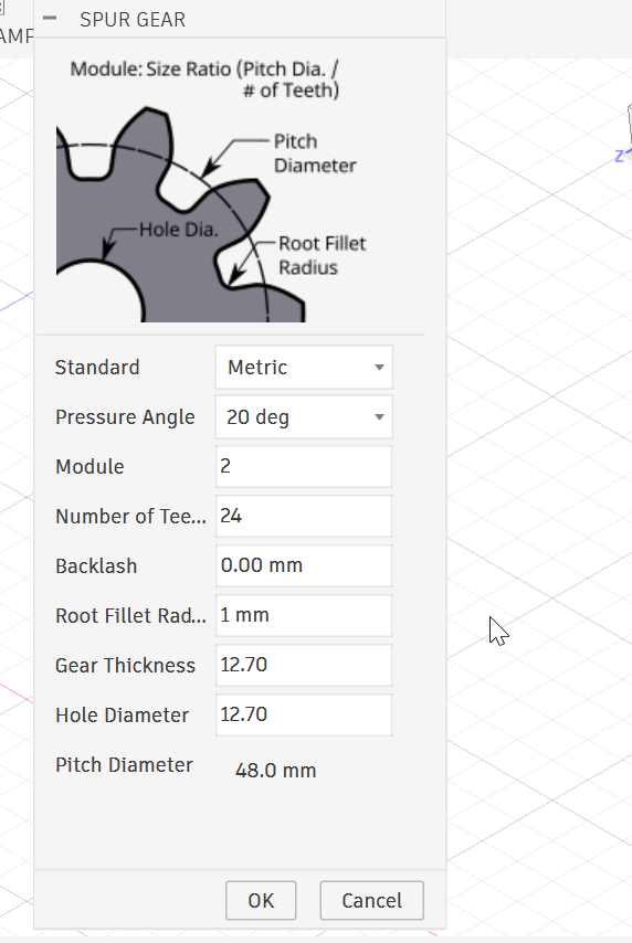
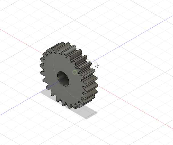
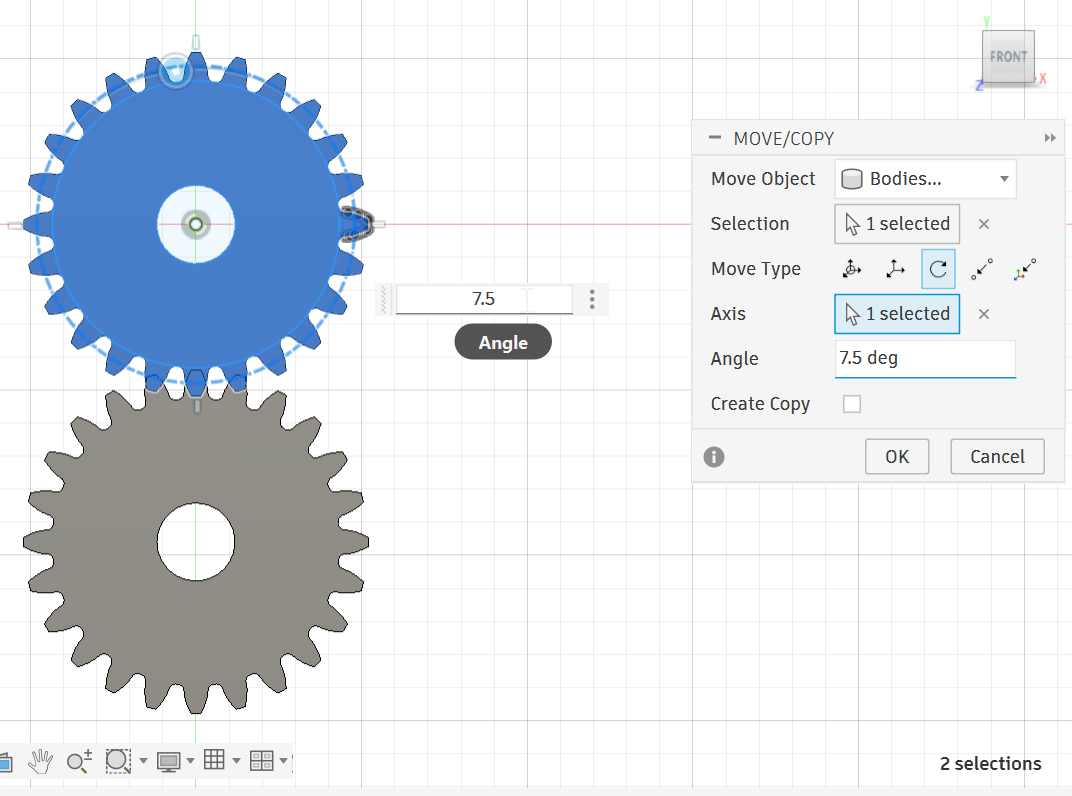
copy gear to use the bottom one to get the rack.
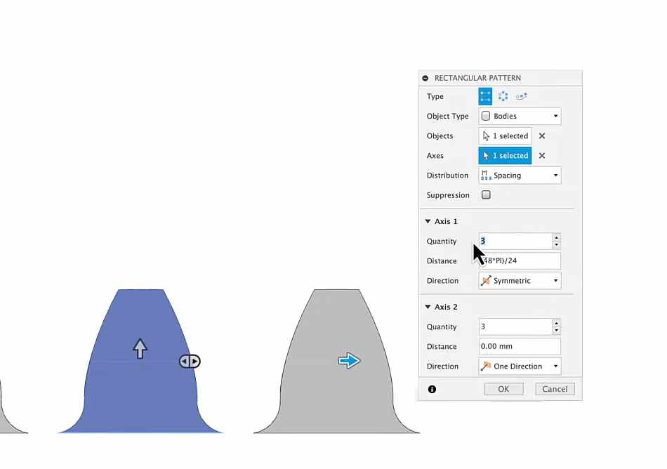
used rectanlur pattern to come up with many teeth i used 21,
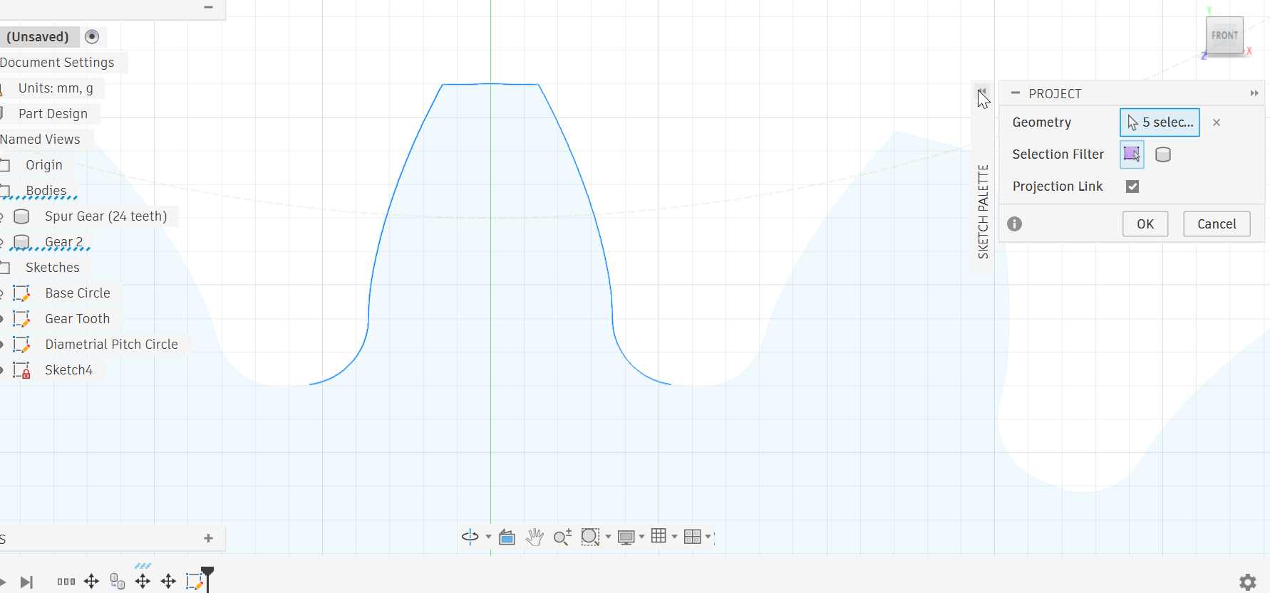
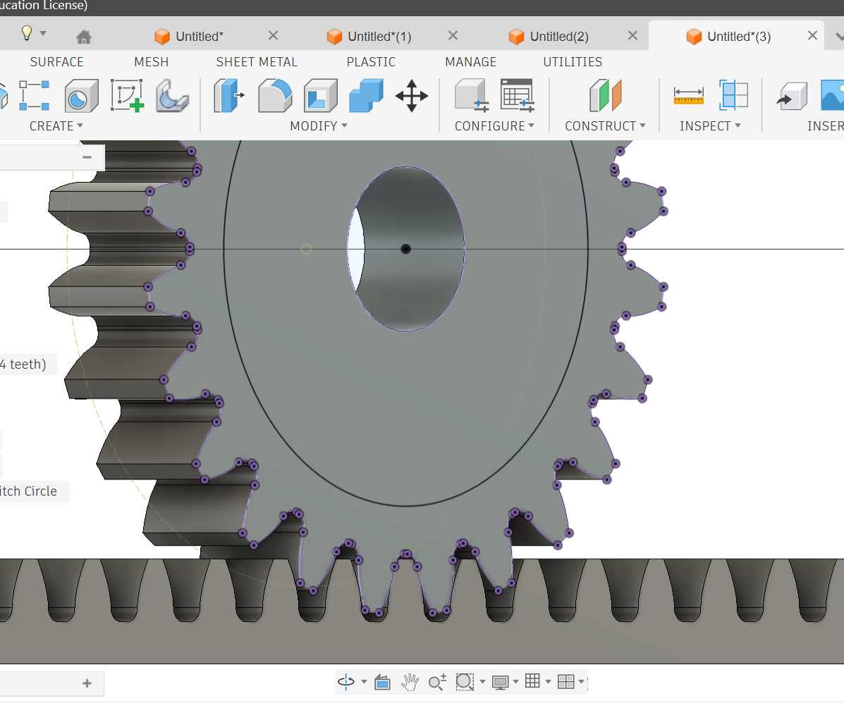
 After that you mark lines from one end to another then you draw a rectangle and extrude to object selcet one side of the object to be the object. then you get this
Now its time to draw the base;
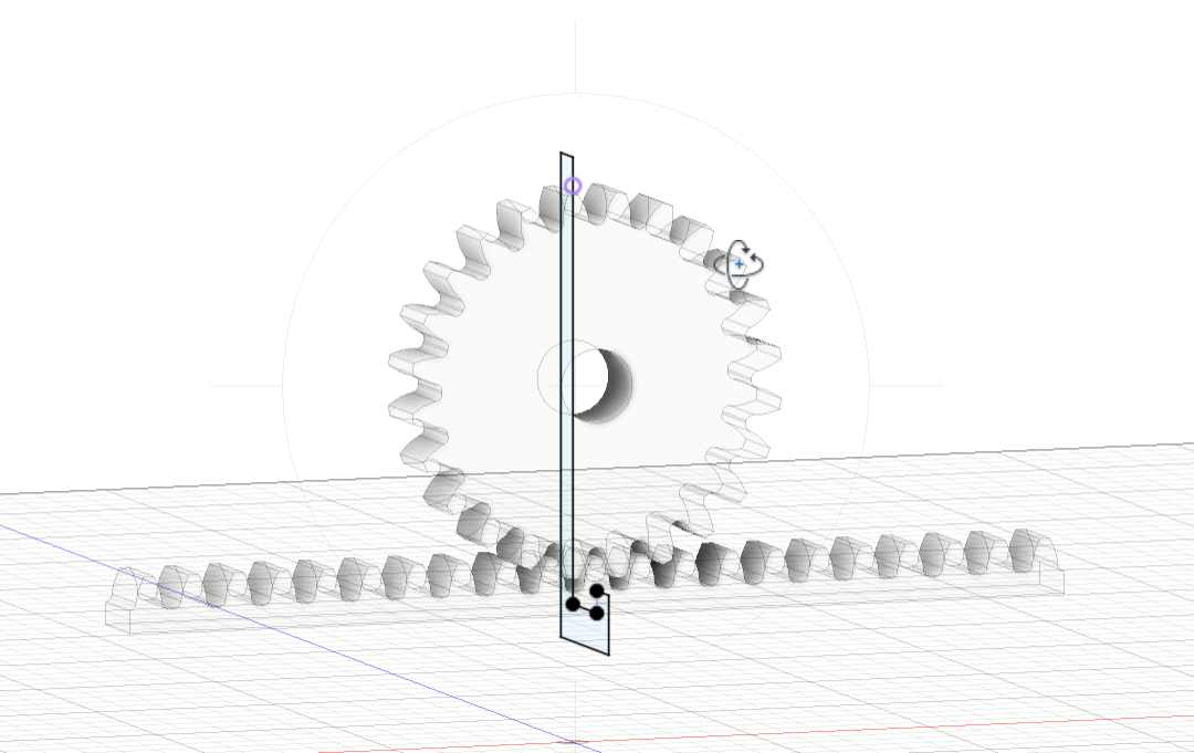
I xtended rhe base, then added two small rectangles one i use as bucket and the other for picking zone, and a rectangular part for my motor
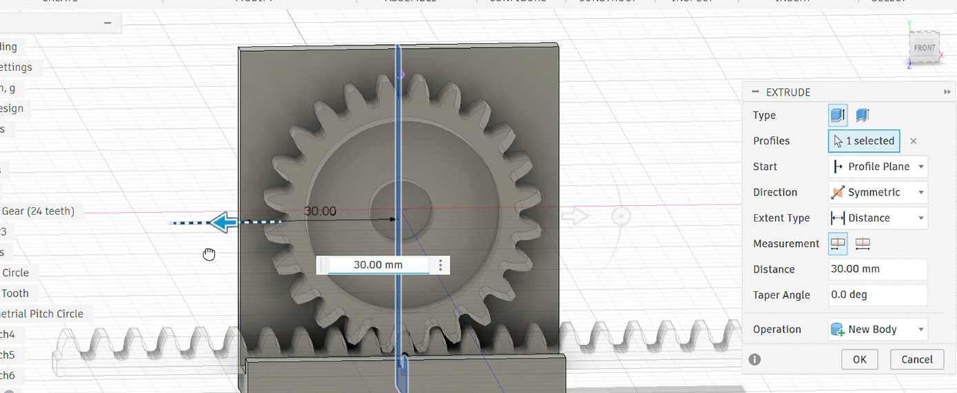
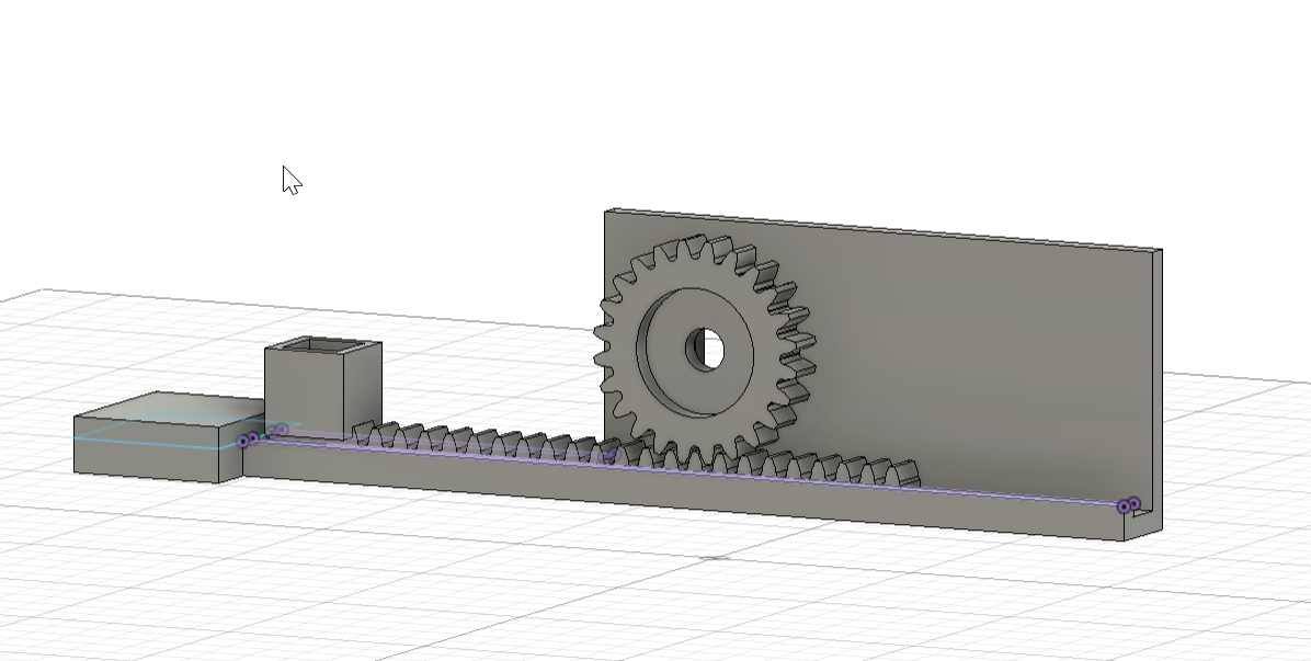 here i extruded the teeth to get the rack
3D printing
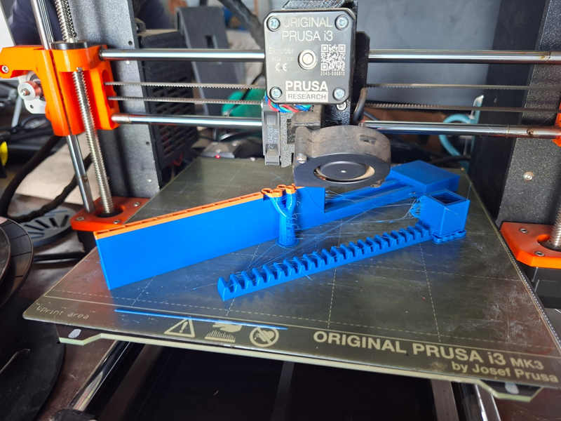
Assembly
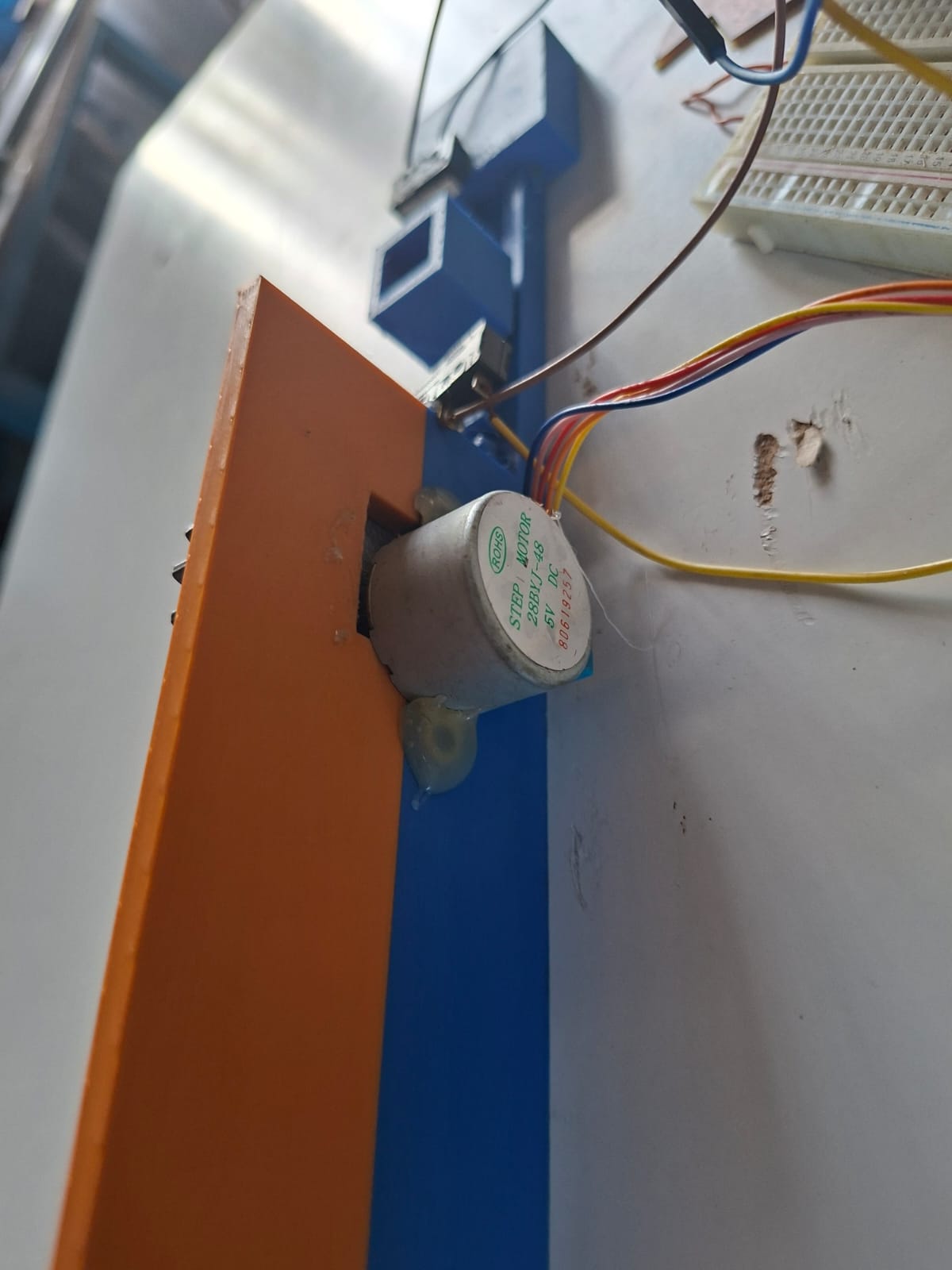
Step Motor
Electronics System
Components Used: ESP32-C3 (controller) 28BYJ-48 stepper motor ULN2003 driver 2 limit switches buzzer
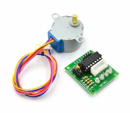
Detailed Summary of Stepper Motor Setup
A 28BYJ-48 5V stepper motor with a ULN2003 driver was used to achieve controlled motion through sequential coil activation.
Connections:
- IN1 → D0
- IN2 → D1
- IN3 → D5
- IN4 → D6
- LIMIT1 → D7 (INPUT_PULLUP)
- LIMIT2 → D3 (INPUT_PULLUP)
- BUZZER → D4
- ULN2003 powered with 5V and shared GND with ESP32
limit swithces
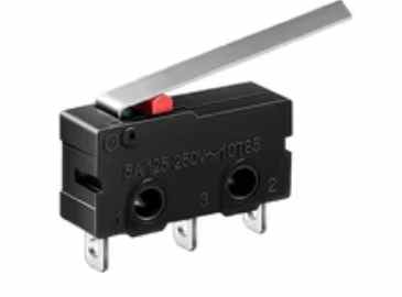
The motor was driven using a step sequence, allowing precise forward and reverse motion. Limit switches were used to change direction, and the buzzer provided feedback.
This setup worked better than the servo because the stepper follows direct step commands, giving stable and predictable motion without needing PWM control.
MQTT
We had a succeful communication between Ethiopia and Kenya since we were in diffrent labs, and my fellow from etipian managed to control my machine
Code
Worked with mqttt,skylab
#include <WiFi.h>
#include <PubSubClient.h>

// ---------------- WIFI ----------------
const char* ssid = "MT";
const char* password = "#@Innovate";

// ---------------- MQTT ----------------
const char* mqtt_server = "broker.hivemq.com";
WiFiClient espClient;
PubSubClient client(espClient);

const char* controlTopic = "esp32/skylab/control";

// ---------------- PINS (YOUR WORKING SETUP) ----------------
#define IN1 D0
#define IN2 D1
#define IN3 D5
#define IN4 D6

const int LIMIT1 = D7;
const int LIMIT2 = D3;
const int BUZZER  = D4;

// ---------------- MOTOR ----------------
int direction = 0;   // NOW MQTT CONTROLLED
int stepIndex = 0;

// step sequence
int steps[8][4] = {
  {1,0,0,0},
  {1,1,0,0},
  {0,1,0,0},
  {0,1,1,0},
  {0,0,1,0},
  {0,0,1,1},
  {0,0,0,1},
  {1,0,0,1}
};

unsigned long lastStepTime = 0;
int stepDelay = 3;

// ---------------- BUZZER ----------------
unsigned long buzzerStart = 0;
bool buzzerOn = false;
int buzzerDuration = 0;

void startBuzzer(int duration) {
  digitalWrite(BUZZER, HIGH);
  buzzerStart = millis();
  buzzerDuration = duration;
  buzzerOn = true;
}

void updateBuzzer() {
  if (buzzerOn && millis() - buzzerStart > buzzerDuration) {
    digitalWrite(BUZZER, LOW);
    buzzerOn = false;
  }
}

// ---------------- MOTOR STEP ----------------
void applyStep(int i) {
  digitalWrite(IN1, steps[i][0]);
  digitalWrite(IN2, steps[i][1]);
  digitalWrite(IN3, steps[i][2]);
  digitalWrite(IN4, steps[i][3]);
}

// ---------------- MQTT CALLBACK ----------------
void callback(char* topic, byte* payload, unsigned int length) {

  String msg = "";
  for (int i = 0; i < length; i++) msg += (char)payload[i];

  msg.trim();

  Serial.print("📩 MQTT Command: ");
  Serial.println(msg);

  if (msg == "HELLO") {
    direction = 1;
  }

  else if (msg == "BYE") {
    direction = -1;
  }

  else if (msg == "STOP") {
    direction = 0;
  }
}

// ---------------- WIFI ----------------
void setup_wifi() {
  Serial.print("🔌 Connecting WiFi...");
  WiFi.begin(ssid, password);

  while (WiFi.status() != WL_CONNECTED) {
    delay(500);
    Serial.print(".");
  }

  Serial.println("\n✅ WiFi connected");
  Serial.println(WiFi.localIP());
}

// ---------------- MQTT RECONNECT ----------------
void reconnect() {
  while (!client.connected()) {
    Serial.println("🔄 Connecting MQTT...");

    if (client.connect("ESP32_Skylab")) {
      Serial.println("✅ MQTT connected");
      client.subscribe(controlTopic);
    } else {
      Serial.print("❌ MQTT failed: ");
      Serial.println(client.state());
      delay(1000);
    }
  }
}

// ---------------- SETUP ----------------
void setup() {

  Serial.begin(115200);
  Serial.println("\n🚀 SYSTEM STARTING...");

  pinMode(IN1, OUTPUT);
  pinMode(IN2, OUTPUT);
  pinMode(IN3, OUTPUT);
  pinMode(IN4, OUTPUT);

  pinMode(LIMIT1, INPUT_PULLUP);
  pinMode(LIMIT2, INPUT_PULLUP);
  pinMode(BUZZER, OUTPUT);

  setup_wifi();

  client.setServer(mqtt_server, 1883);
  client.setCallback(callback);
}

// ---------------- LOOP ----------------
void loop() {

  if (!client.connected()) reconnect();
  client.loop();

  bool limit1 = (digitalRead(LIMIT1) == LOW);
  bool limit2 = (digitalRead(LIMIT2) == LOW);

  // 🚨 LIMIT SAFETY (kept from your working system
  if (limit1) {
    direction = -1;
    startBuzzer(120);
  }

  if (limit2) {
    direction = 1;
    startBuzzer(120);
  }

  // ⚡ MOTOR STEPPING
  if (direction != 0 && millis() - lastStepTime >= stepDelay) {
    lastStepTime = millis();

    stepIndex += direction;

    if (stepIndex > 7) stepIndex = 0;
    if (stepIndex < 0) stepIndex = 7;

    applyStep(stepIndex);
  }

  updateBuzzer();
}
Challenges / Issues
- Servo Motor Instability (initial test)
I first tried using an SG90 servo but it was not suitable for this system because:
low torque jittering at startup inaccurate positioning under load
I replaced it with a stepper motor which gave better control.
Improvements
If I continue developing this machine, I would:
replace plastic gears with stronger material (acrylic or nylon) improve rack guiding system for smoother motion add display for local feedback (LCD or OLED) improve MQTT reliability using local fallback mode redesign base for easier maintenance Learning Outcomes
From this assignment, I learned:
how mechanical motion can be converted into controlled digital movement how rack and pinion systems behave under real load how to design gears properly using Fusion 360 add-ins instead of manual drawing how MQTT can be used for real-time remote machine control importance of testing mechanical systems before adding automation