11. Networking and Communication
individual assignment: • design, build, and connect wired or wireless node(s) with network or bus addresses and local input &/or output device(s) group assignment: • send a message between two projects
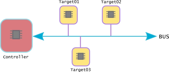
Bus protocols
Are standardised ways for various embedded system components or devices to communicate with one another in embedded systems. A bus is a means of communication that enables the transfer of data and control signals between various modules, including peripherals, memory devices, and microcontrollers. Bus protocols provide out the guidelines and norms for addressing, synchronisation, and data transfer, providing seamless interoperability.
SPI (Serial Peripheral Interface), which uses a master-slave setup with several slaves, is another widely used protocol. SPI is frequently used to interface with gadgets like flash memory, sensors, and display controllers because of its high-speed data transfer capabilities.A popular and easy-to-use serial communication protocol is the Universal Asynchronous Receiver/Transmitter (UART), which is frequently used for point-to-point communication between devices.
I2C (Inter-Integrated Circuit), a bus protocol that is often used, has a master-slave design for communication. It enables numerous devices with separate addresses to be connected to the same bus. Connecting sensors, EEPROMs, and other low-speed peripherals is frequently done via the I2C protocol.
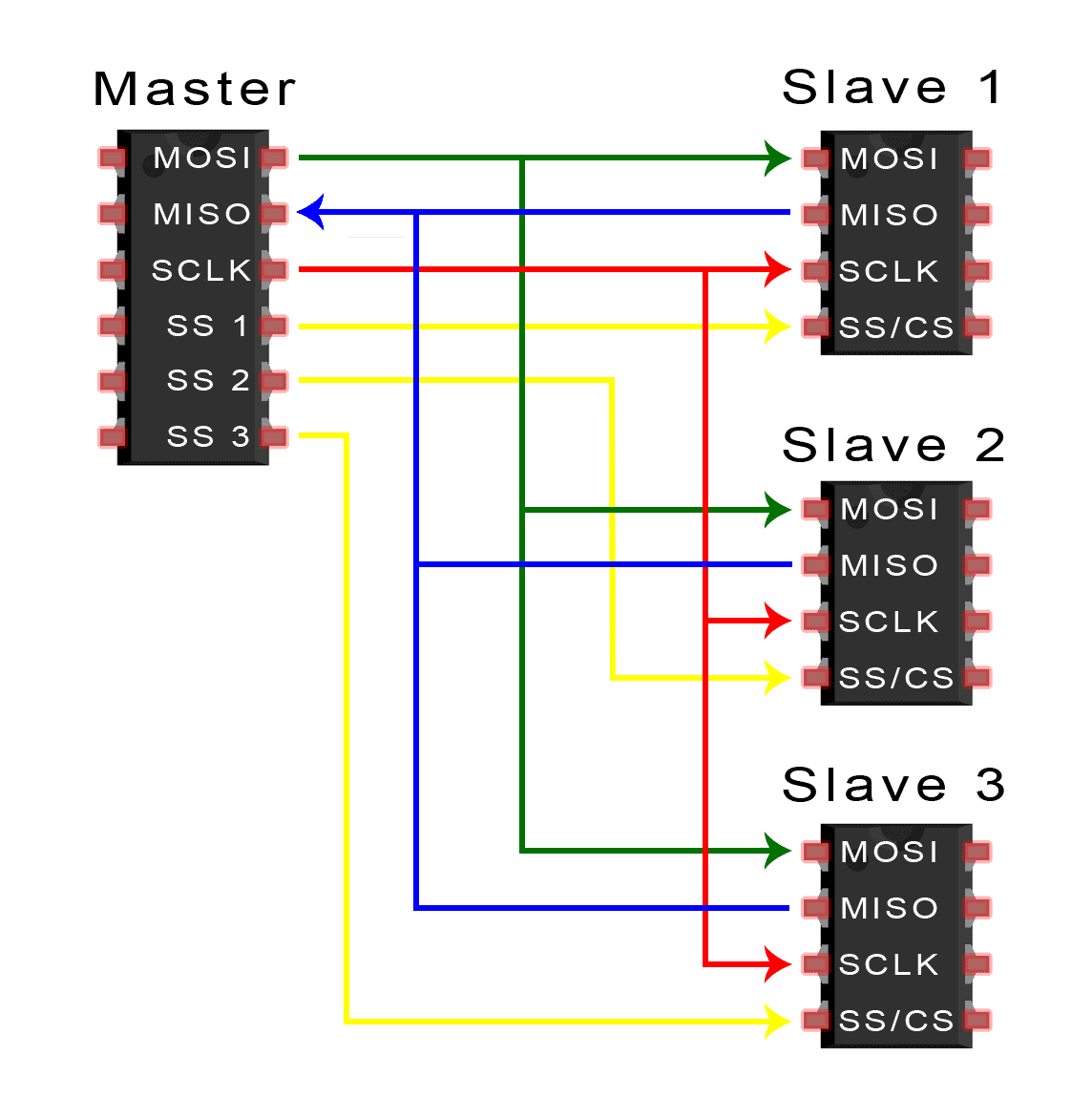 image from https://www.circuitbasics.com/
What is Protocal
Set of rules that govern communication of devices on the internet.
Protocols ensure that data is sent, received, and interpreted correctly between devices.
Two main frameworks are commonly referenced:
OSI Model
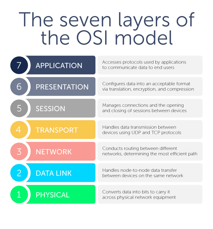 , imgae from blue cat networks.
TCP/IP
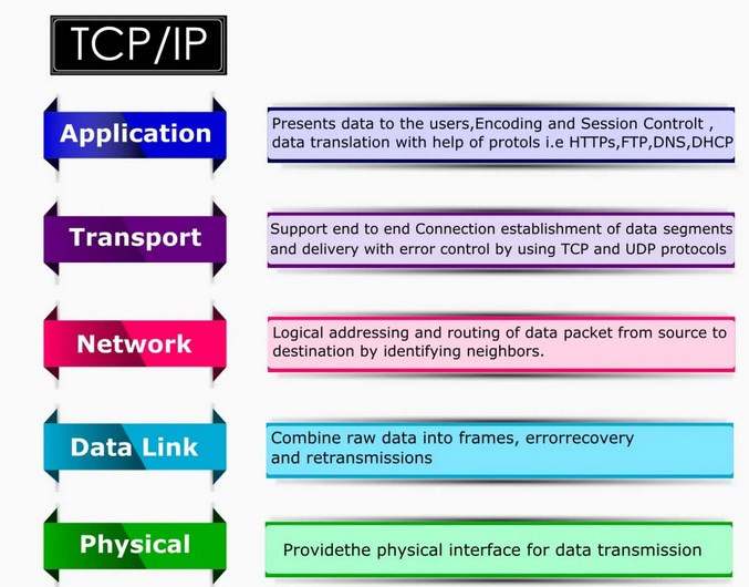 image src, Ebyte
| Layer | OSI / TCP-IP | Safe Tap Components | Protocol/Bus Used |
|---|---|---|---|
| 7 / 4 | Application | Node button & LED | MQTT / HTTP |
| 6-5 / 4 | Presentation & Session | Data formatting & message handling | MQTT serialization |
| 4 / 3 | Transport | Reliable message delivery | TCP (HTTP) / UDP (MQTT) |
| 3 / 2 | Network | ESP32 IP addressing | IP routing |
| 2 / 2 | Data Link | Wi-Fi MAC, frames | IEEE 802.11 (Wi-Fi) |
| 1 / 1 | Physical | Wi-Fi radio or wired buses | SPI, I2C, UART |
Individual assignment
HTTP PROTOCAL
Safe Tap
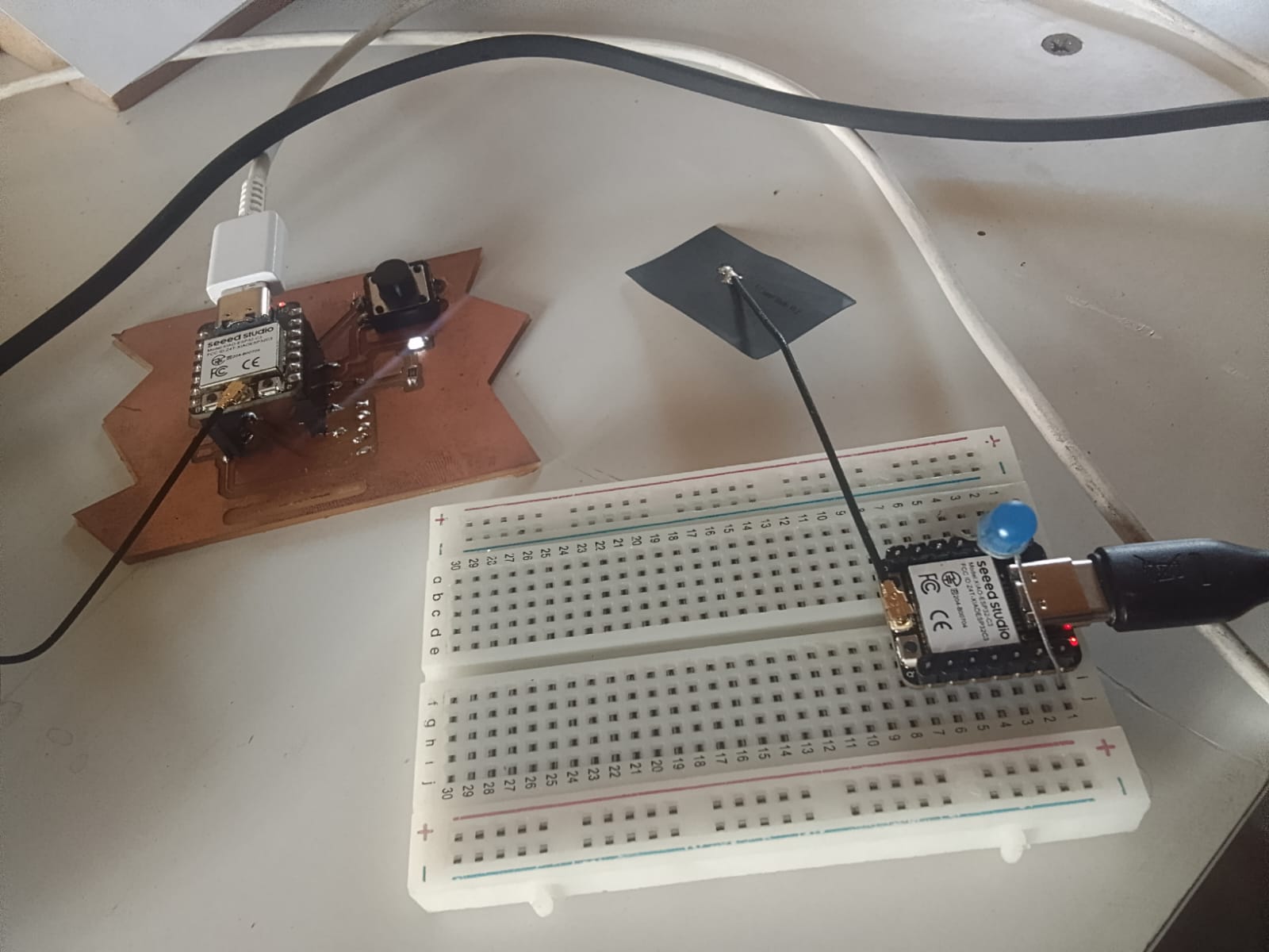
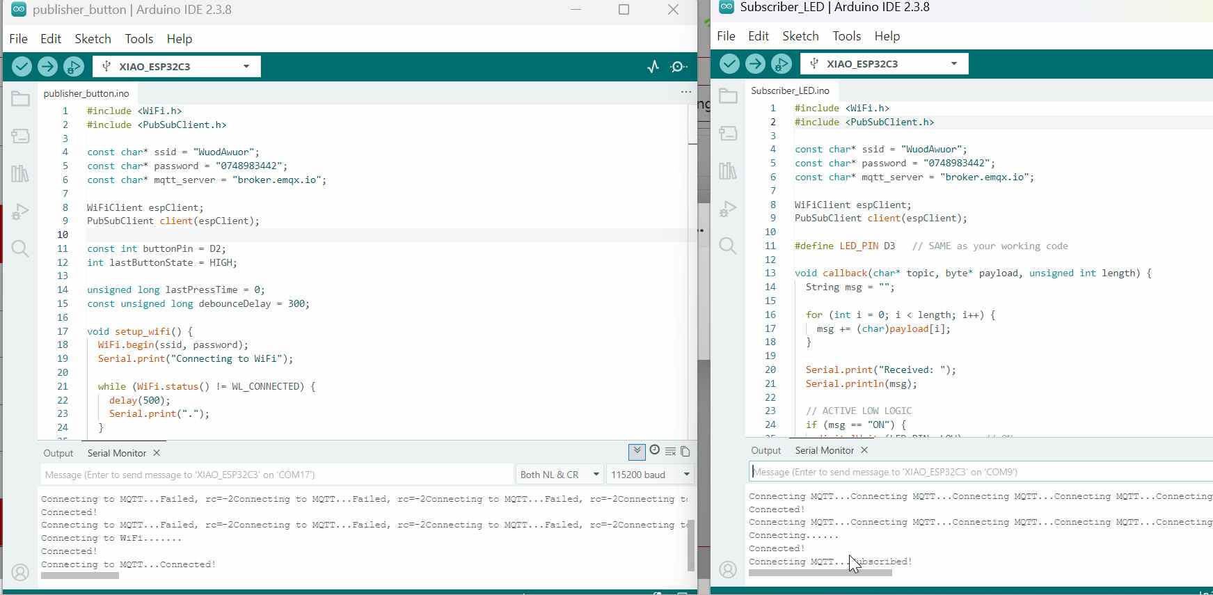
In this project, I designed two Wi-Fi-enabled nodes using ESP32. Each node has a unique IP address, local input (button), and output (LED). When the button is pressed on one node, it sends an HTTP request over Wi-Fi to another node, which receives the message and activates its LED. the protocal here is using http ptotocal which is used to send commands over http
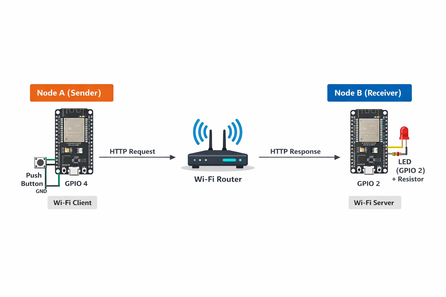
First i used the xiao esp32-c3 and connected one as server and another as client, now client can send command to server by turning ON and OFF LED on server using push button.
I did this conenction through a wifi. I realized that my esp works better when connected to 2G netwrk, so I connected to a 2G. I generated the following codes by chatgpt, and used.
Server
#include <WiFi.h>
#include <WebServer.h>

const char* ssid = "Aduvan";
const char* password = "Aduvani#@321";

const int ledPin = D3;   // LED pin (active-low)
bool ledState = false;    // false = OFF

WebServer server(80);

void handleRoot() {
  // Toggle state
  ledState = !ledState;

  // ACTIVE-LOW control
  if (ledState) {
    digitalWrite(ledPin, LOW);   // LED ON
  } else {
    digitalWrite(ledPin, HIGH);  // LED OFF
  }

  // Debug
  Serial.println(ledState ? "ON" : "OFF");

  // Response to client
  server.send(200, "text/plain", ledState ? "ON" : "OFF");
}

void setup() {
  Serial.begin(115200);

  pinMode(ledPin, OUTPUT);

  // Ensure LED starts OFF (active-low)
  digitalWrite(ledPin, HIGH);

  WiFi.begin(ssid, password);
  Serial.print("Connecting");

  while (WiFi.status() != WL_CONNECTED) {
    delay(500);
    Serial.print(".");
  }

  Serial.println("\nConnected!");
  Serial.print("Server IP: ");
  Serial.println(WiFi.localIP());

  server.on("/", handleRoot);
  server.begin();

  Serial.println("Server ready");
}

void loop() {
  server.handleClient();
}
client
#include <WiFi.h>
#include <HTTPClient.h>

const char* ssid = "Aduvan";
const char* password = "Aduvani#@321";

const int buttonPin = D2;
int lastButtonState = HIGH;

const char* serverIP = "172.17.88.116";

unsigned long lastPressTime = 0;
const unsigned long debounceDelay = 300;

void setup() {
  Serial.begin(115200);
  pinMode(buttonPin, INPUT_PULLUP);

  WiFi.begin(ssid, password);
  Serial.print("Connecting to WiFi");

  while (WiFi.status() != WL_CONNECTED) {
    delay(500);
    Serial.print(".");
  }

  Serial.println("\nConnected to WiFi");
}

void loop() {
  int buttonState = digitalRead(buttonPin);
  unsigned long now = millis();

  if (lastButtonState == HIGH && buttonState == LOW && (now - lastPressTime) > debounceDelay) {

    Serial.println("Button pressed → Sending request");

    if (WiFi.status() == WL_CONNECTED) {
      HTTPClient http;
      WiFiClient client;  //

      String url = String("http://") + serverIP + "/";
      Serial.println(url);

      http.begin(client, url);  //
      int httpCode = http.GET();

      Serial.print("HTTP Code: ");
      Serial.println(httpCode);

      if (httpCode > 0) {
        String payload = http.getString();
        Serial.print("Server: ");
        Serial.println(payload);
      } else {
        Serial.println("Request failed!");
      }

      http.end();
    }

    lastPressTime = now;
  }

  lastButtonState = buttonState;
}
Idea here is to make my two boards communicate over the mqtt and one board can turn a LED on the other board
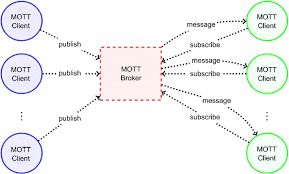
## MQTT PROTOCOL MQTT is a lightweight publish–subscribe messaging protocol designed for low-bandwidth and resource-constrained devices. It operates using three main components: a publisher, which sends messages; a subscriber, which receives messages; and a broker (server), which manages the communication between the two. The broker ensures that any message published to a specific topic is delivered to all clients subscribed to that topic, enabling efficient and real-time data exchange.
 iage from research Gate.
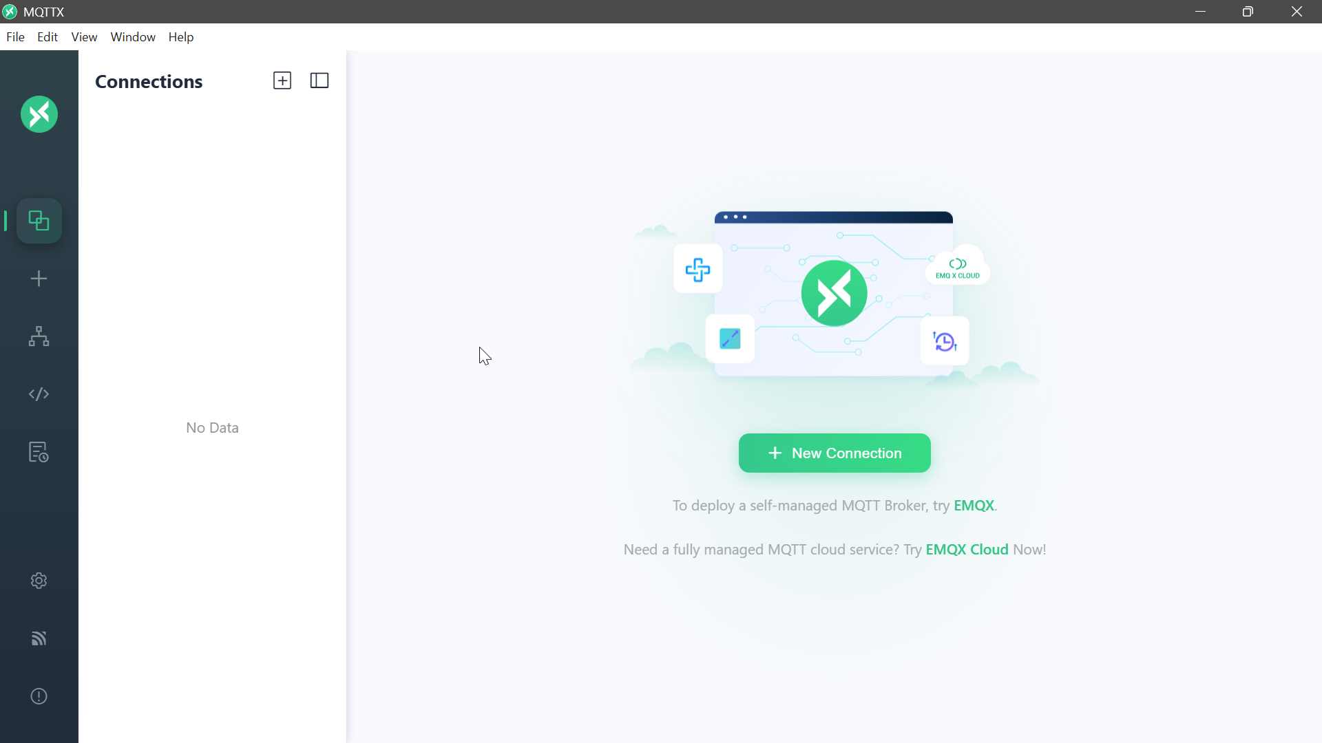
Download and Installation
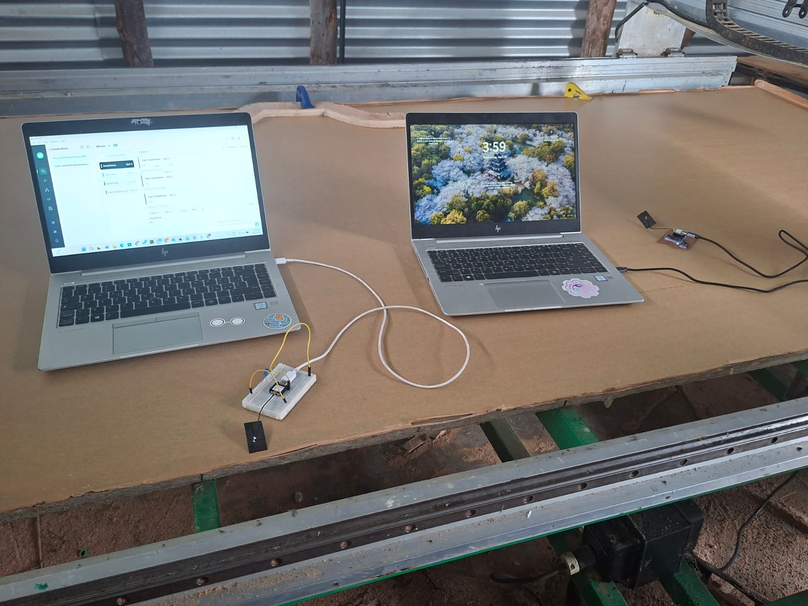
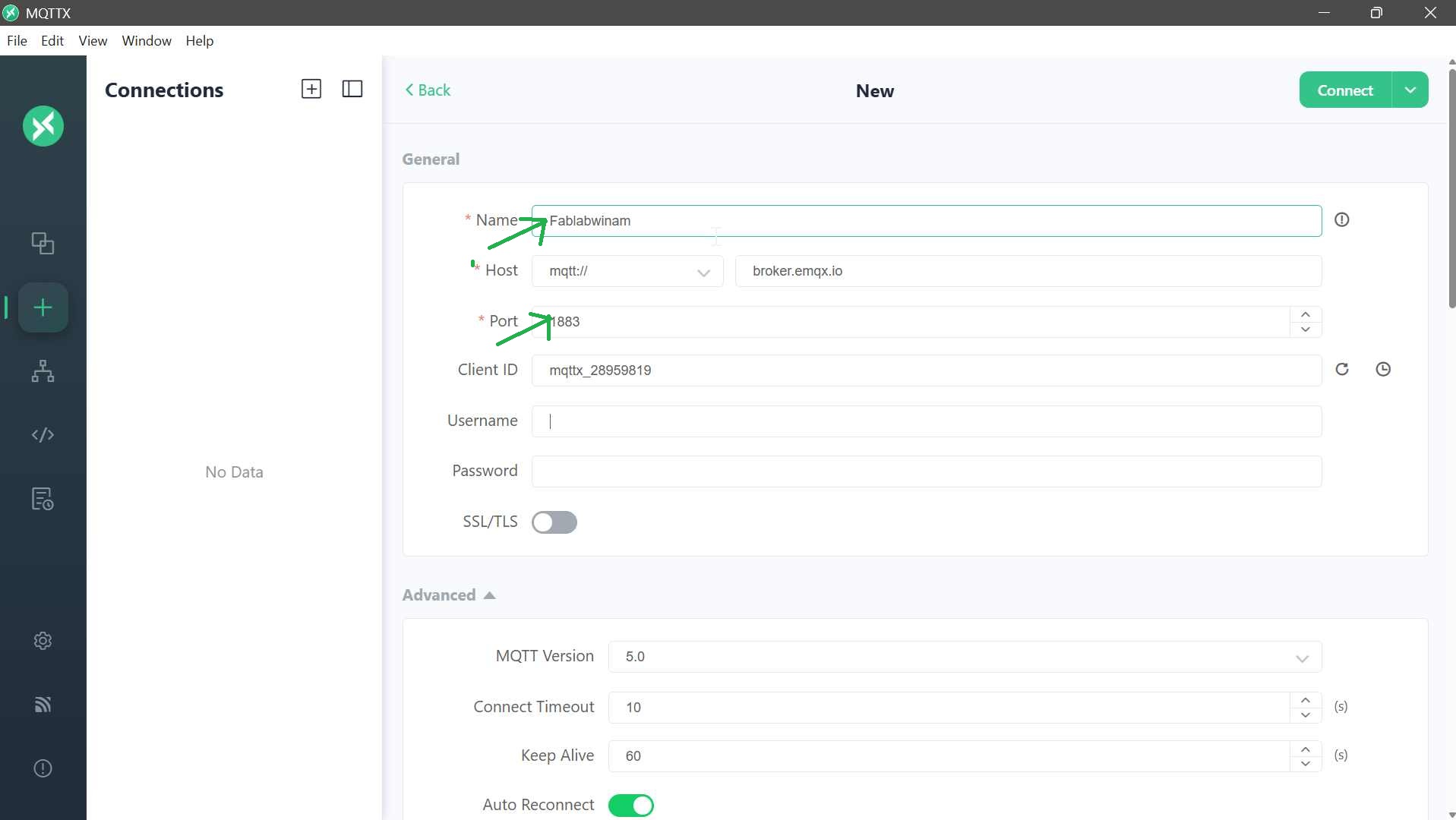
For this implementation, MQTTX was used as the client tool. The application was downloaded from MQTT_Link , and the x64 version was selected to match the Windows operating system. After installation, a new broker connection was created within the MQTTX interface. The broker was named Fablabwinam, and the default MQTT port 1883 was used. This port is the standard TCP port for MQTT communication and allows devices to connect and exchange messages without encryption.
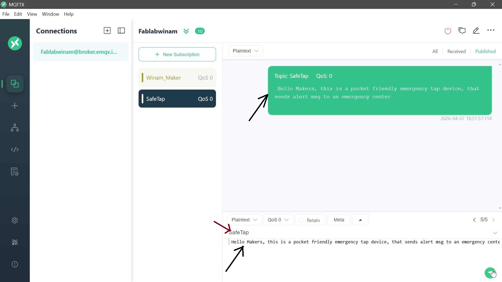
Communicating with my topics
To enable communication, topics were created through the subscription feature. A topic acts as a logical channel through which messages are sent and received. In this setup, topics such as Winam_Maker and SafeTap were defined. Subscribing to these topics allows the client to listen for any incoming messages published under the same topic name. To create one just click new connection
To test the functionality of the MQTT setup, messages were published using the plain text payload format. By specifying a topic (e.g., SafeTap) and sending test messages, it was possible to verify that the system was working correctly. The messages were successfully received on the subscribed dashboard, confirming proper communication between the publisher, broker, and subscriber.
My Application
publisher
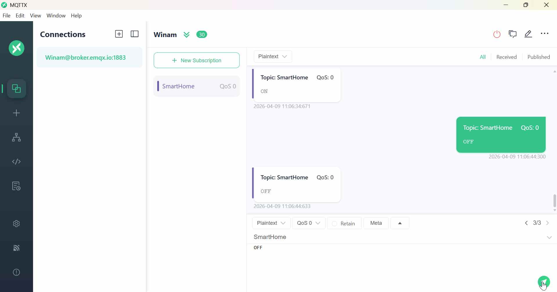
The first code is the button code, which acts as the MQTT publisher. Its main role is to read the state of the button and send messages to the MQTT broker. The ESP board connects to the WiFi network using the provided SSID and password, then connects to the MQTT broker (broker.emqx.io). Whenever the button is pressed, the code publishes the message “ON” to the topic “SmartHome”. When the button is released, it publishes “OFF” to the same topic. In MQTT terms, the ESP board here is the publisher, the messages “ON” and “OFF” are the payload, and “SmartHome” is the topic, which acts like a channel for the messages.
#include <WiFi.h>
#include <PubSubClient.h>

const char* ssid = "WuodAwuor";
const char* password = "0748983442";
const char* mqtt_server = "broker.emqx.io";

WiFiClient espClient;
PubSubClient client(espClient);

const int buttonPin = D2;
int lastButtonState = HIGH;

unsigned long lastPressTime = 0;
const unsigned long debounceDelay = 300;

void setup_wifi() {
  WiFi.begin(ssid, password);
  Serial.print("Connecting to WiFi");

  while (WiFi.status() != WL_CONNECTED) {
    delay(500);
    Serial.print(".");
  }

  Serial.println("\nConnected!");
}

void reconnect() {
  while (!client.connected()) {
    Serial.print("Connecting to MQTT...");
    if (client.connect("XIAO_Button")) {
      Serial.println("Connected!");
    } else {
      Serial.print("Failed, rc=");
      Serial.print(client.state());
      delay(2000);
    }
  }
}

void setup() {
  Serial.begin(115200);
  pinMode(buttonPin, INPUT_PULLUP);

  setup_wifi();
  client.setServer(mqtt_server, 1883);
}

void loop() {
  if (!client.connected()) reconnect();
  client.loop();

  int buttonState = digitalRead(buttonPin);
  unsigned long now = millis();

  if (lastButtonState == HIGH && buttonState == LOW && (now - lastPressTime) > debounceDelay) {

    Serial.println("Button pressed → Sending MQTT");

    client.publish("SmartHome", "ON");

    lastPressTime = now;
  }

  if (lastButtonState == LOW && buttonState == HIGH && (now - lastPressTime) > debounceDelay) {

    Serial.println("Button released → Sending MQTT");

    client.publish("SmartHome", "OFF");

    lastPressTime = now;
  }

  lastButtonState = buttonState;
}
Subscriber The second code is the LED code, which acts as the MQTT subscriber. This board also connects to the same WiFi network and the same MQTT broker. Instead of sending messages, it subscribes to the topic “SmartHome”. This means it tells the broker, “Send me all messages that are published to this topic.” When a message arrives, the callback function is executed: if the message is “ON”, the LED turns on (using active-low logic, LOW = on), and if the message is “OFF”, the LED turns off. In MQTT terms, this board is a subscriber, the LED reacts based on the payload received, and the broker acts as the central server delivering messages from publishers to subscribers.
#include <WiFi.h>
#include <PubSubClient.h>

const char* ssid = "WuodAwuor";
const char* password = "0748983442";
const char* mqtt_server = "broker.emqx.io";

WiFiClient espClient;
PubSubClient client(espClient);

#define LED_PIN D3   // SAME as your working code

void callback(char* topic, byte* payload, unsigned int length) {
  String msg = "";

  for (int i = 0; i < length; i++) {
    msg += (char)payload[i];
  }

  Serial.print("Received: ");
  Serial.println(msg);

  // ACTIVE LOW LOGIC
  if (msg == "ON") {
    digitalWrite(LED_PIN, LOW);   // ON
  } else if (msg == "OFF") {
    digitalWrite(LED_PIN, HIGH);  // OFF
  }
}

void setup_wifi() {
  WiFi.begin(ssid, password);
  Serial.print("Connecting");

  while (WiFi.status() != WL_CONNECTED) {
    delay(500);
    Serial.print(".");
  }

  Serial.println("\nConnected!");
}

void reconnect() {
  while (!client.connected()) {
    Serial.print("Connecting MQTT...");
    if (client.connect("XIAO_LED")) {
      client.subscribe("SmartHome");
      Serial.println("Subscribed!");
    } else {
      delay(2000);
    }
  }
}

void setup() {
  Serial.begin(115200);
  pinMode(LED_PIN, OUTPUT);

  digitalWrite(LED_PIN, HIGH); // OFF initially

  setup_wifi();
  client.setServer(mqtt_server, 1883);
  client.setCallback(callback);
}

void loop() {
  if (!client.connected()) reconnect();
  client.loop();
}
I created broker @ broker.emqx.io and gave it a name Winam this name is not a must you use it as Winam@broker.emqx.io ESP recognizes cpp **broker.emqx.io**.
Now i used my mobile phone hotspot to connect and ensured it is 2G/3G since wit 5Git challenges to connect.
Ensure both boards are connected to both wifi and mqttx
Key Take aways
Xiao regnizes D1,D0…and you name then using “D” i had struglled without D and nothing was working, Again not all pins are good for outputs, i struggled with pin 10 which was unstabled and i change to D3 and my led worked so well.
IP addressing enables devices to communicate on a network. In private networks, addresses like 192.168.1.x belong to Class C, where 192.168.1 is the network and the last number is the host (device). Devices on the same network share the network part but must have different host values (e.g., 192.168.1.192 and 192.168.1.70). The network–host division depends on the class: Class A (1 network, 3 host), Class B (2 network, 2 host), Class C (3 network, 1 host).