7. Computer controlled machining
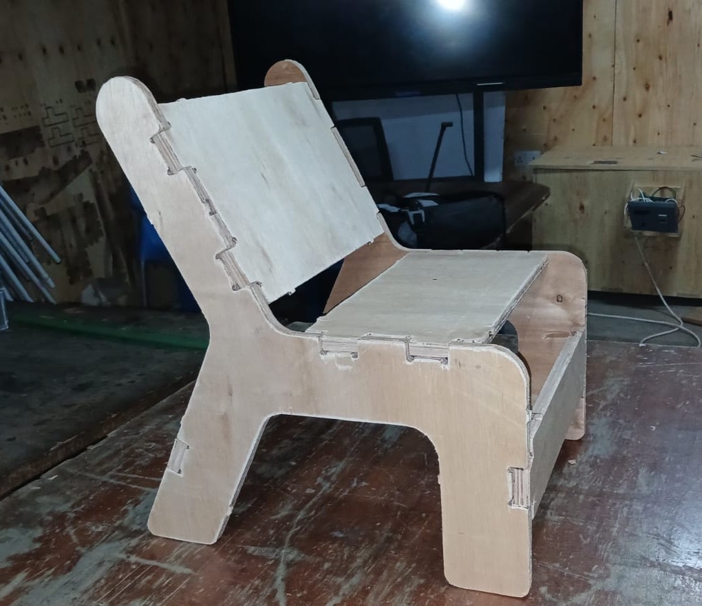
individual assignment • make (design+mill+assemble) something big (~meter-scale) • extra credit: don’t use fasteners or glue • extra credit: include curved surfaces • extra credit: use three-axis toolpaths
## My design I designed a chair 600mmx450mm for my baby, using fusion 360
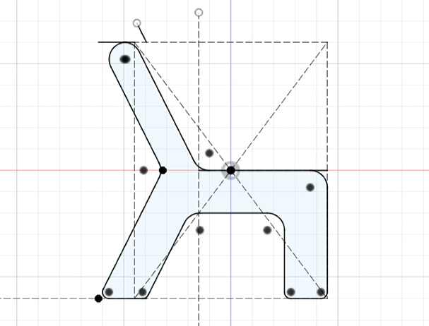
The first step in the sketch involved constructing a reference framework using construction lines. A rectangular boundary was drawn to define the overall design space of the chair profile. The approximate height of this frame was set to 600 mm, while the width was defined at approximately 450 mm. Within this frame, additional construction lines were drawn diagonally from corner to corner. These diagonals intersect at the center point, which serves as a key alignment reference for the entire design..and constriant then trime the lines and remianed with the chair , and read to extrude, then later on mirrow the frames with 400mm.,
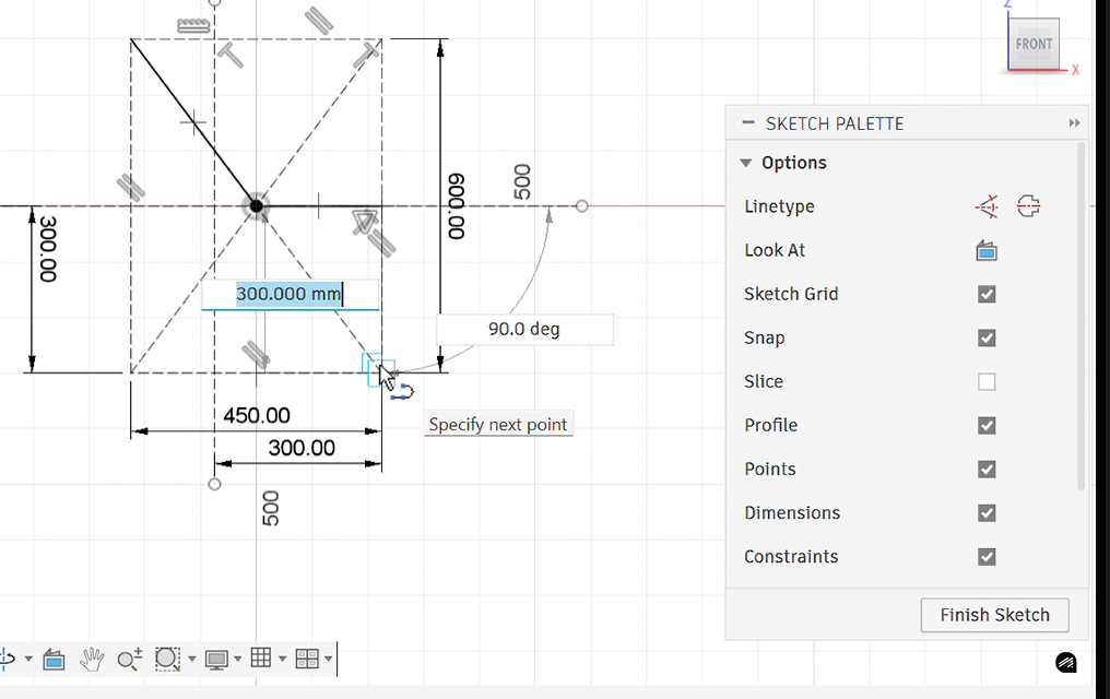
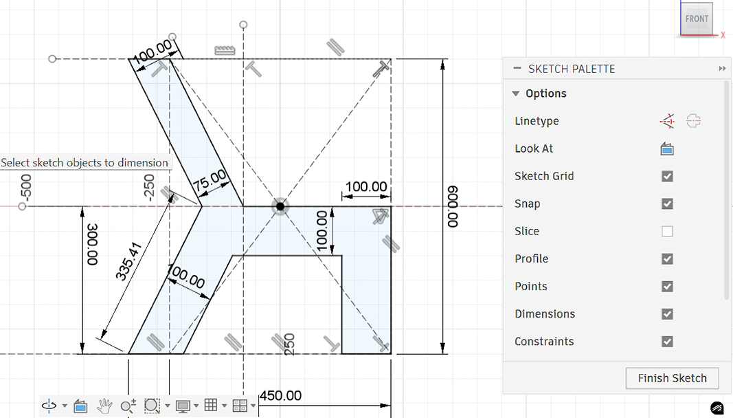
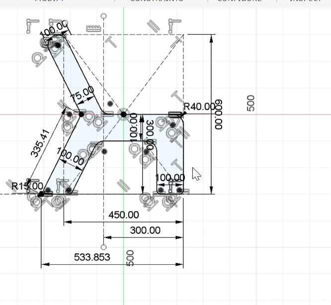
After establishing the reference geometry, the next step was to define the main structural elements of the chair. The chair frame was designed using angled lines extending from the top of the reference frame toward the central anchor point. These angled elements form the back support of the chair and contribute to the ergonomic posture of the user. The back support was given an approximate length of 400 mm to ensure that it would provide adequate support for the upper body.
## Parametric Design
To make the design flexible and easy to modify, I used parametric modeling in Fusion 360. Instead of entering fixed dimensions directly into sketches, I defined user parameters that control the main dimensions of the chair.
Parameters Used
| Parameter | Value | Description |
|---|---|---|
| Chair_Height | 600 mm | Overall chair height |
| Chair_Width | 450 mm | Width of the chair side profile |
| Chair_Depth | 300 mm | Distance between the two side frames |
| Material_Thickness | 18 mm | Plywood thickness |
| Backrest_Length | 400 mm | Length of the back support |
| Slot_Width | Material_Thickness | Width of press-fit joints |
The use of parameters allows the chair dimensions to be modified easily by changing a single value. For example, changing the material thickness automatically updates all slot dimensions, ensuring a proper press-fit assembly.
(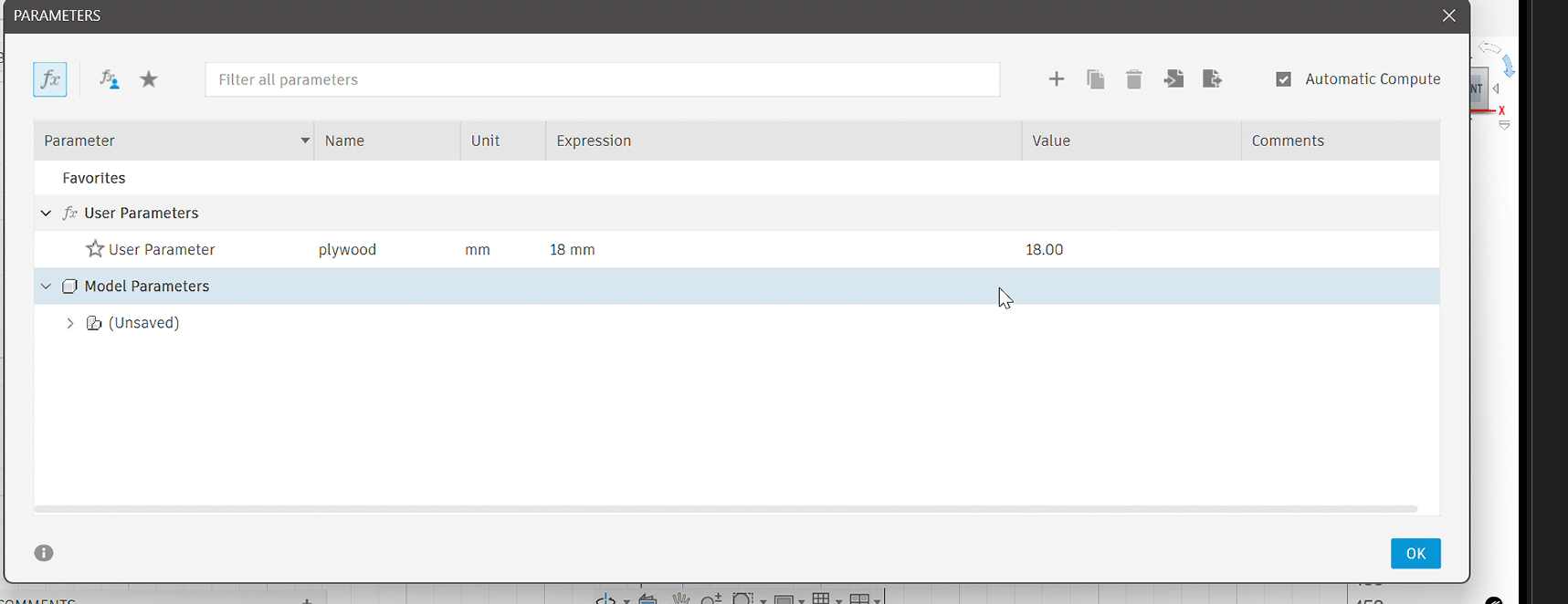 )
)
After extruding the chair side profile, I used the mirror tool in Fusion 360 to create the second frame.After extruding the chair side profile, I used the mirror tool in Fusion 360 to create the second frame. I mirrored the first frame using a construction plane and positioned the mirrored frame 300 mm away from the original to define the width of the chair.
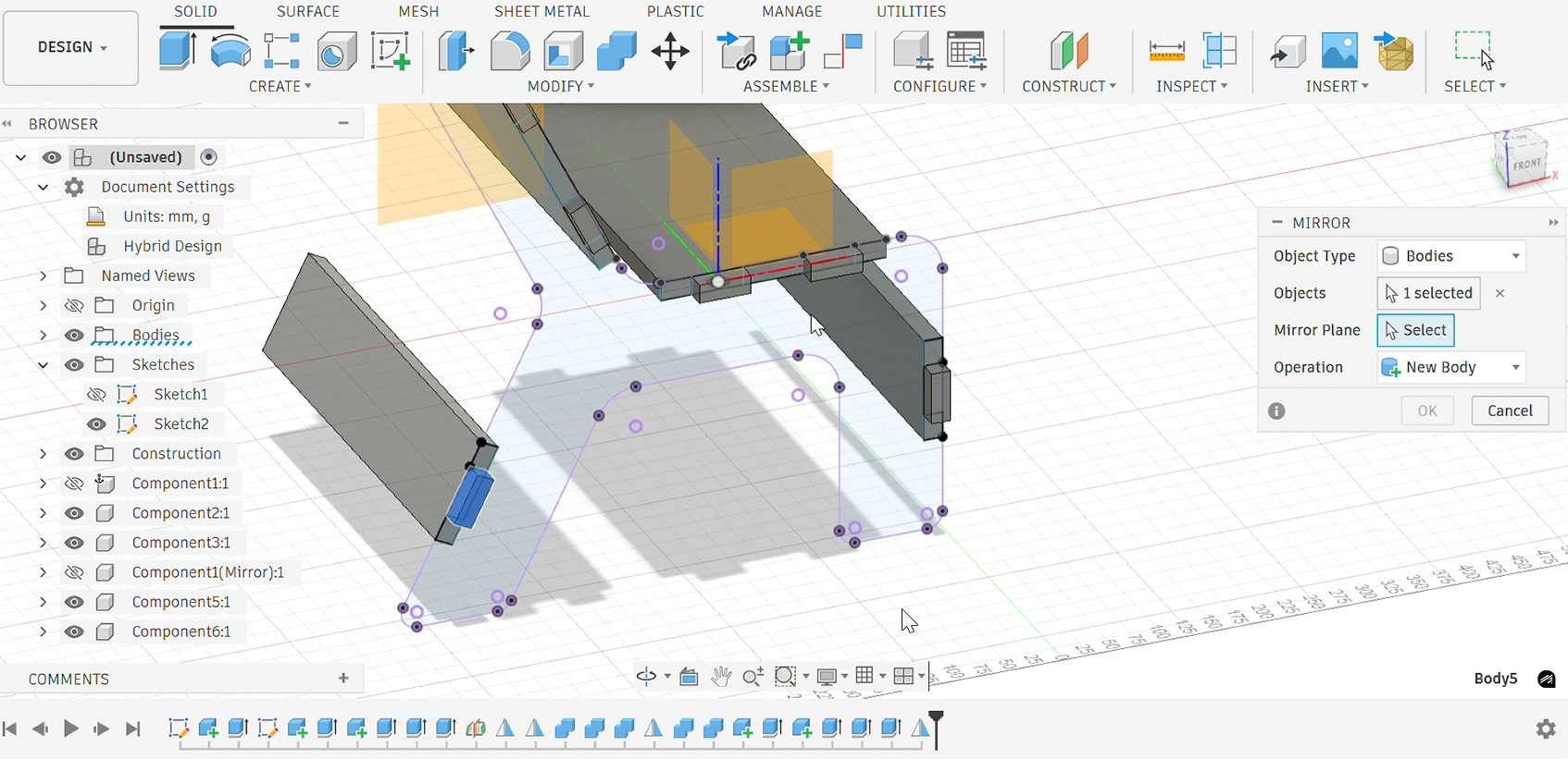
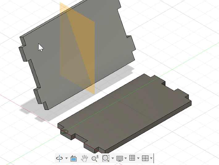
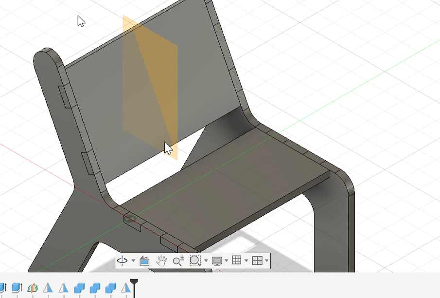
Now i decided to combine all the parts that needed to be combined,
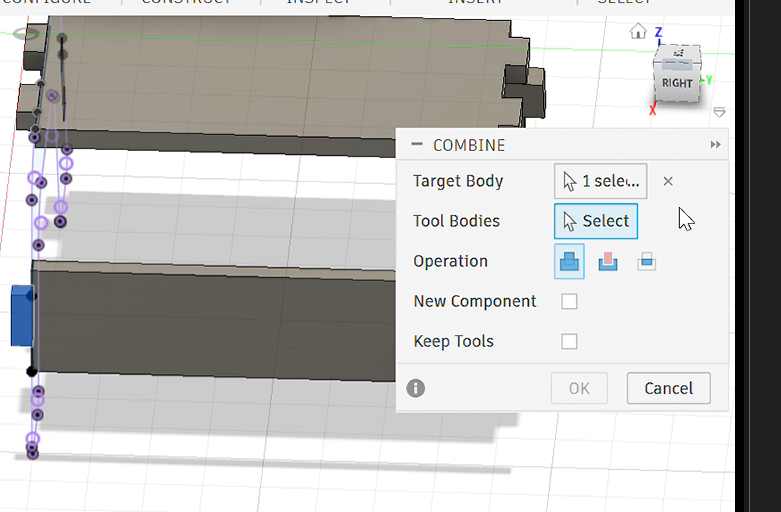
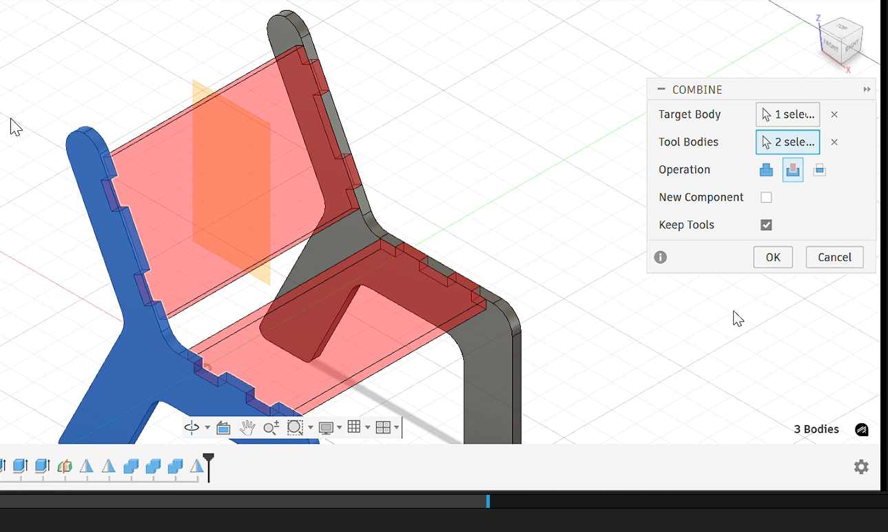
After combineing now i had my chair and ready to add dogbones
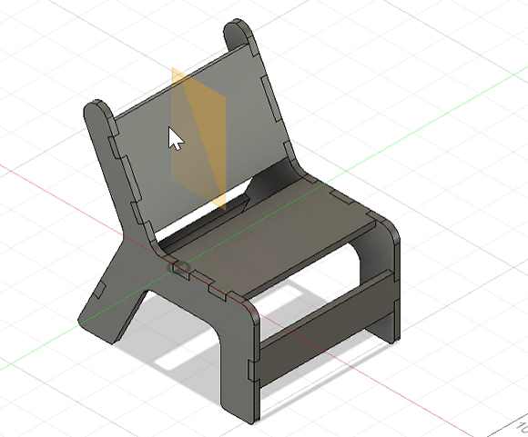
## Adding Dogbones
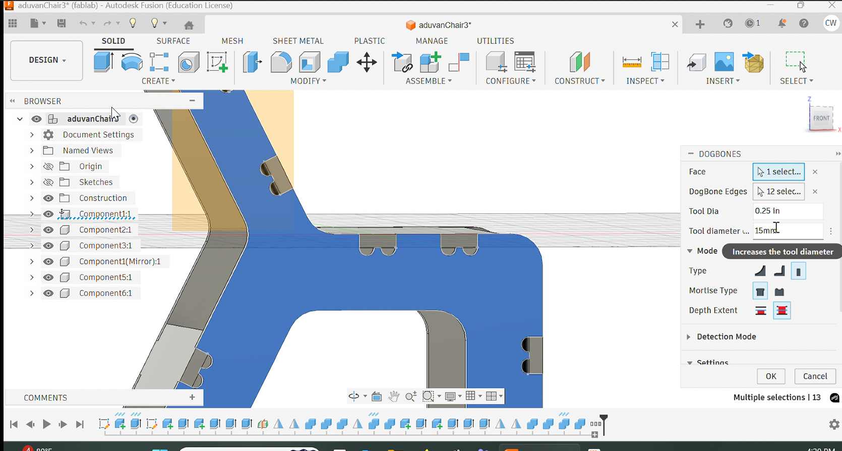
In CNC cutting, dogbones are essential because the milling tool is round and cannot create perfect internal square corners. Dogbones add small circular cuts at internal corners so that press-fit parts can fit properly during assembly.To add dogbones to my design, I downloaded a dogbone script from GitHub: dogbone-git
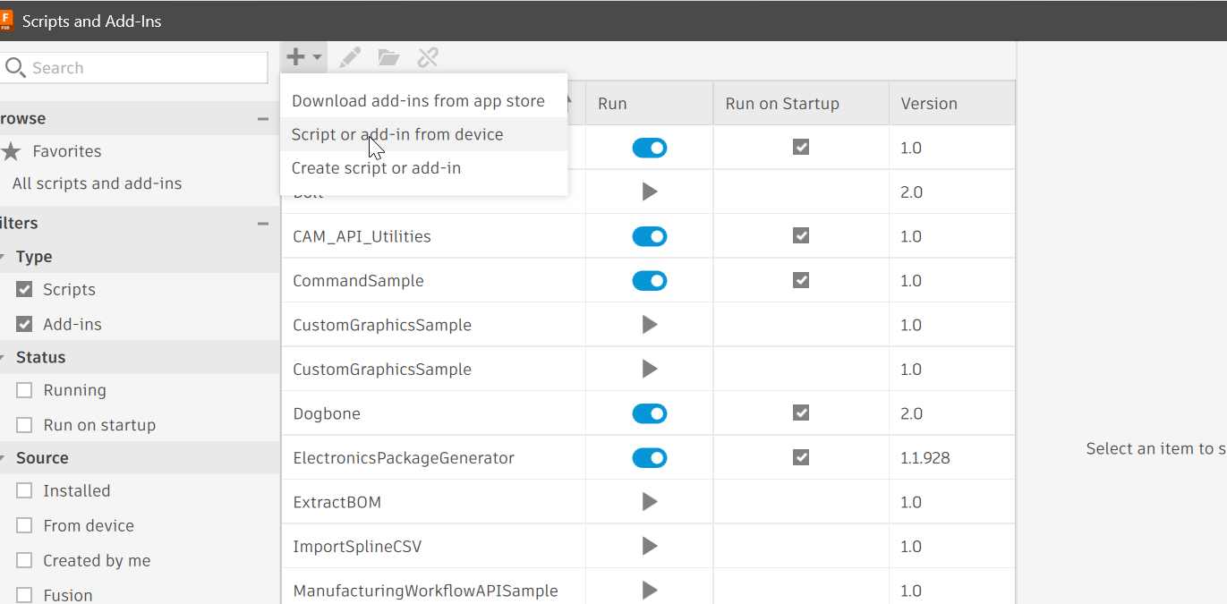
After downloading the script, I extracted the folder on my computer. In Fusion 360, I opened the Scripts and Add-Ins window using Shift + S. I then clicked the + button and selected “Script or Add-In from Device”. While selecting the folder, I made sure to choose the parent folder that contains the script files.
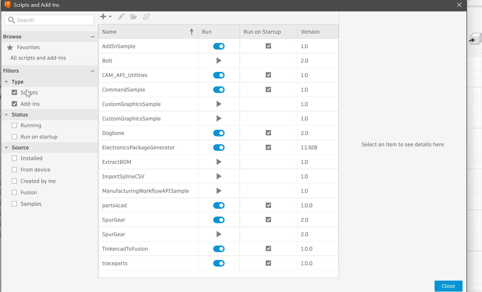
After importing the script, I enabled the option to automatically run the script whenever Fusion 360 starts. This ensures the dogbone tool is always available.
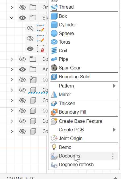
Once installed, the dogbone tool appears in the Design workspace under the Create tab. From there, I selected Dogbone to apply dogbones to the internal corners of my design
While adding the dogbones, I selected the tool diameter to match the milling bit that will be used on the CNC machine. I also chose the normal dogbone type because it works well for most press-fit joints and allows parts to fit together more easily.
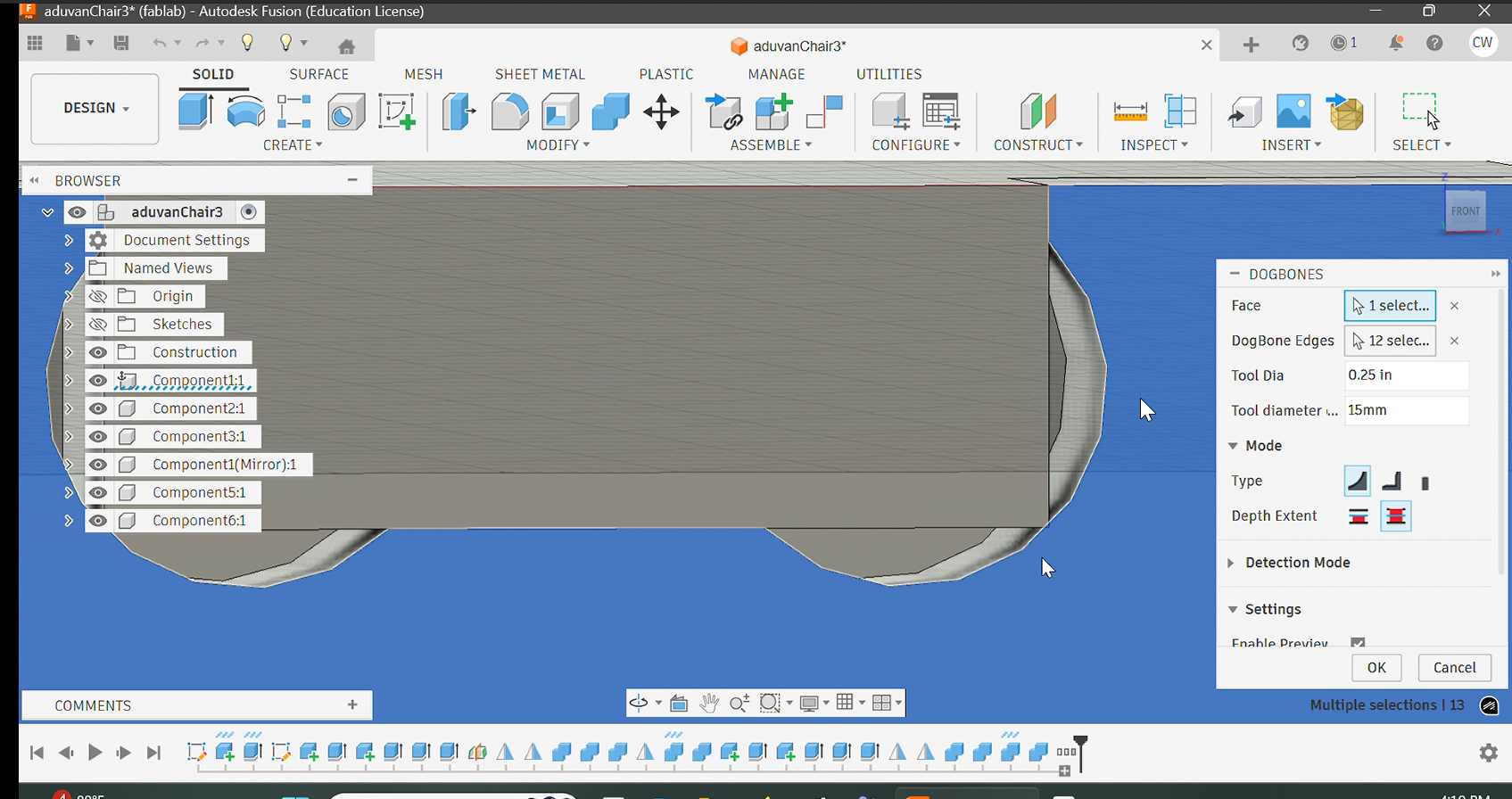
.After applying the dogbones, the internal corners were modified to accommodate the round cutting tool, ensuring that the parts will assemble correctly after CNC machining
## Preparation for cutting
To prepare the design for CNC cutting, I first created a reference sheet that represents the working area of the CNC machine. I started by creating a new sketch on the XY plane in Fusion 360. Using the Two-Point Rectangle tool, I drew a rectangle that represents the size of the CNC router bed. The dimensions used were 2438 mm × 1219 mm, which correspond to the working area of the CNC machine. This rectangle acts as the cutting sheet where all components will be placed
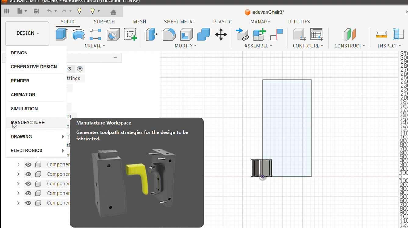
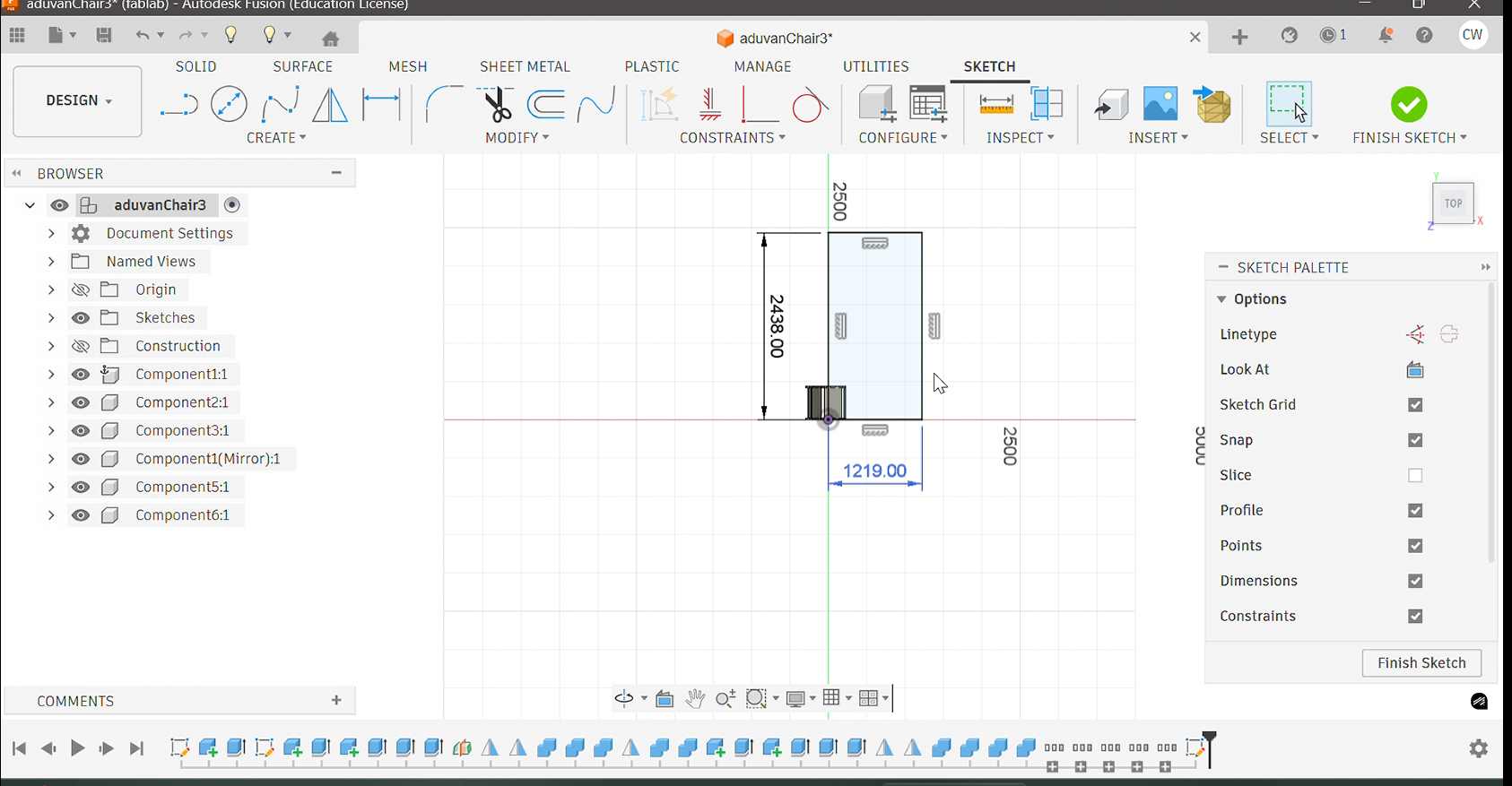
After creating the sheet, I needed to arrange all the components on this plane to ensure they fit within the CNC cutting area. Under the Modify tab, I selected the Arrange tool. In the Arrange dialog, I set the envelope to the CNC sheet I had created. Under Objects, I selected all the components that needed to be cut. I then arranged the components by dragging them onto the sheet while ensuring all parts remained within the cutting boundary.
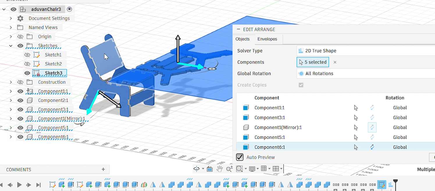
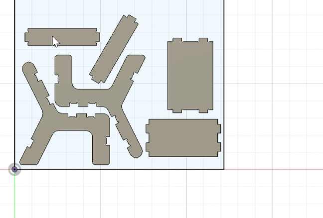
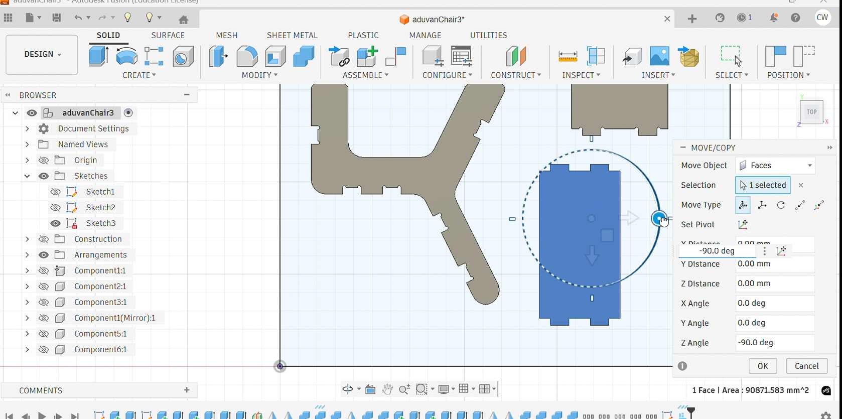
To refine the placement of the components, I used the Move/Copy tool, which can be accessed quickly by pressing M on the keyboard. This allowed me to reposition the components more precisely and organize them efficiently on the sheet. Proper arrangement is important to maximize material usage and avoid overlapping parts during the cutting process.
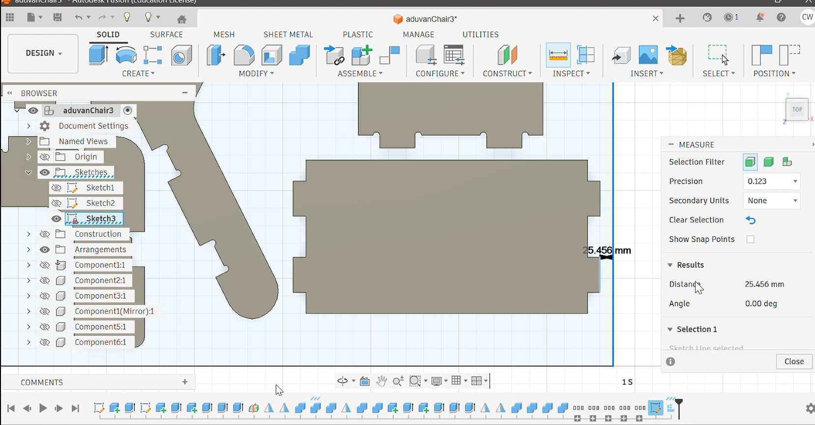
To verify the spacing between components and ensure safe cutting distances, I used the Inspect → Measure tool. This tool allowed me to measure the distance between components and between components and the edge of the sheet. Maintaining proper spacing prevents the cutting tool from interfering with adjacent parts. In my case, I maintained approximately 25.456 mm distance from the sheet edge and about 21.265 mm spacing between some components. These measurements were taken by selecting the edges of two objects and observing the distance shown in the measurement tool.
CNC Setup for Flat Pack Cutting
After arranging the components, I configured the machining setup in Fusion 360. Since the design is a flat-pack project, the cutting operation is performed on a flat sheet using 2D machining strategies.
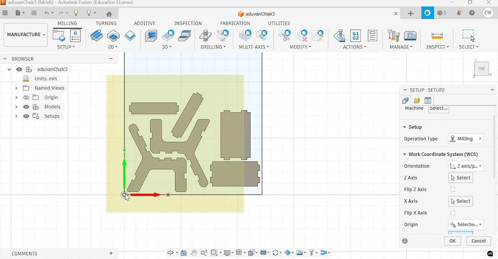
I switched to the Manufacture workspace and created a New Setup. The Operation Type was set to Milling, and under the Model section, I selected all the bodies representing the parts to be cut.
Next, I defined the orientation by selecting Z Axis / Plane & X Axis. This ensured that the Z-axis was perpendicular to the sheet surface, allowing the CNC machine to cut vertically into the material.
Finally, I defined the origin point, which determines where the CNC machine begins cutting. Under Origin, I selected Stock Box Point and set it to the bottom-left corner of the material, which is commonly used as the reference point during CNC operations.
Toolpath Configuration
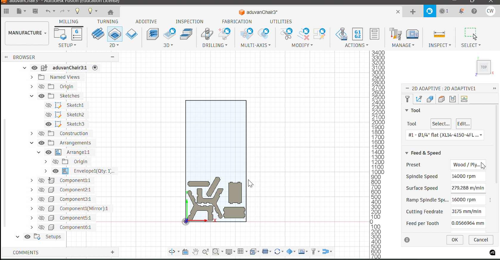
To generate the cutting paths, I used a 2D Contour toolpath, which is suitable for cutting the outer profiles of flat-pack components.
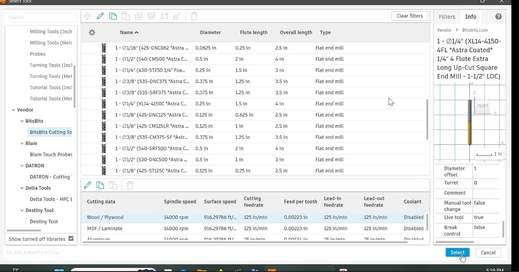
For the cutting tool, I selected a 1/4-inch Astrolite coated end mill, which is commonly used for CNC routing in plywood or MDF sheets.
Machining Parameters
The following machining parameters were used during toolpath generation:
| Setting | Value |
|---|---|
| Tool Diameter | 6.35 mm |
| Spindle Speed | 18000 RPM |
| Feed Rate | 3000 mm/min |
| Plunge Rate | 800 mm/min |
| Maximum Stepdown | 6.35 mm |
These settings were selected to achieve clean cuts in plywood while maintaining safe cutting conditions and reducing tool load.
In the Passes settings, I enabled Multiple Depths to allow the tool to cut the material gradually instead of in a single pass. The maximum stepdown depth was set to 6.35 mm, ensuring safe and efficient cutting.
Under the Geometry tab, I selected the edges of all the components to define the cutting paths. I also set the Retract Height Offset to 20 mm to ensure the tool safely lifts above the material when moving between cuts.
I did use TABS
Simulation
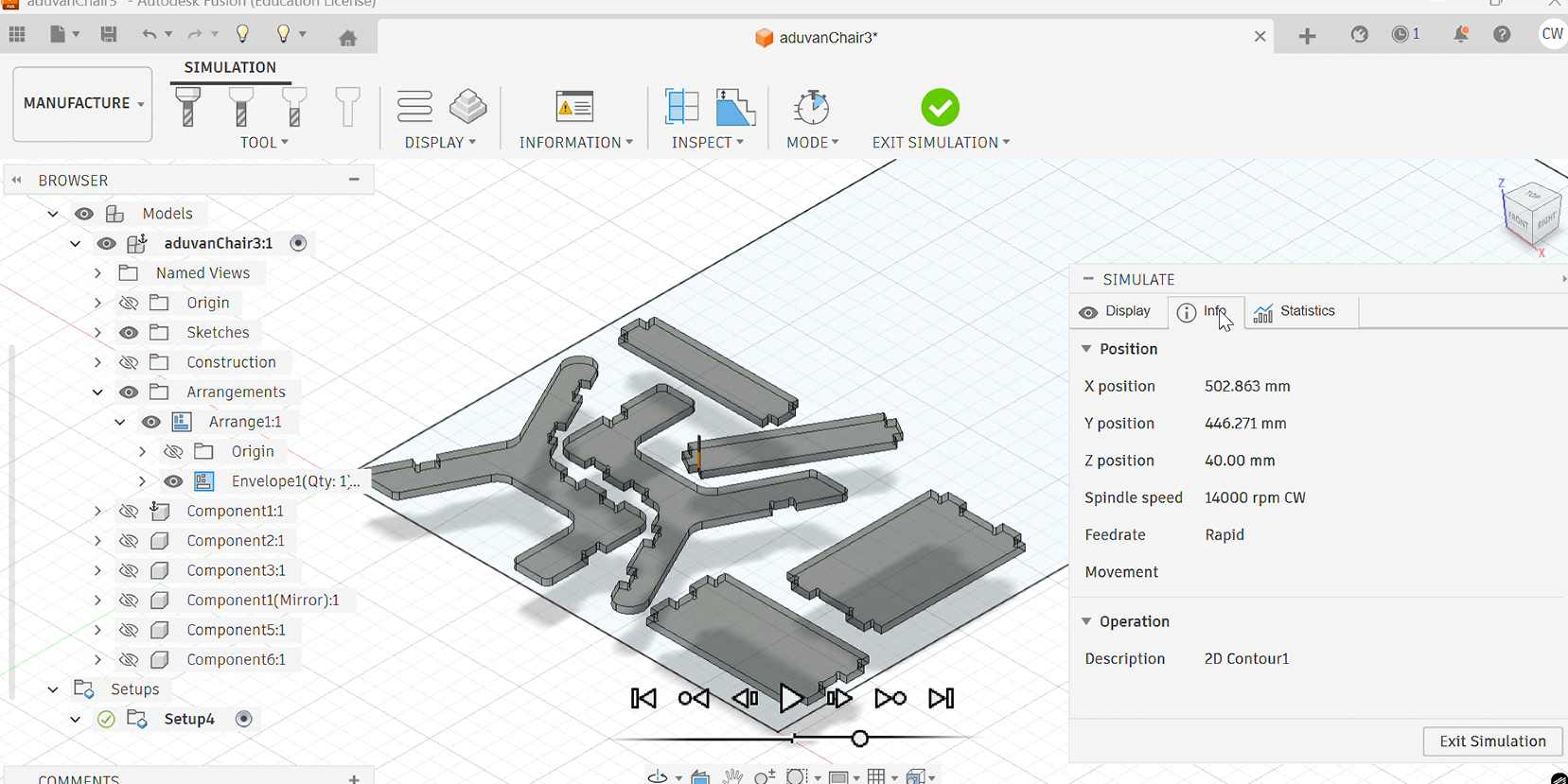
Before exporting the toolpaths, I ran a simulation to verify the machining process. I opened the simulation by right-clicking the Contour toolpath and selecting Simulate.
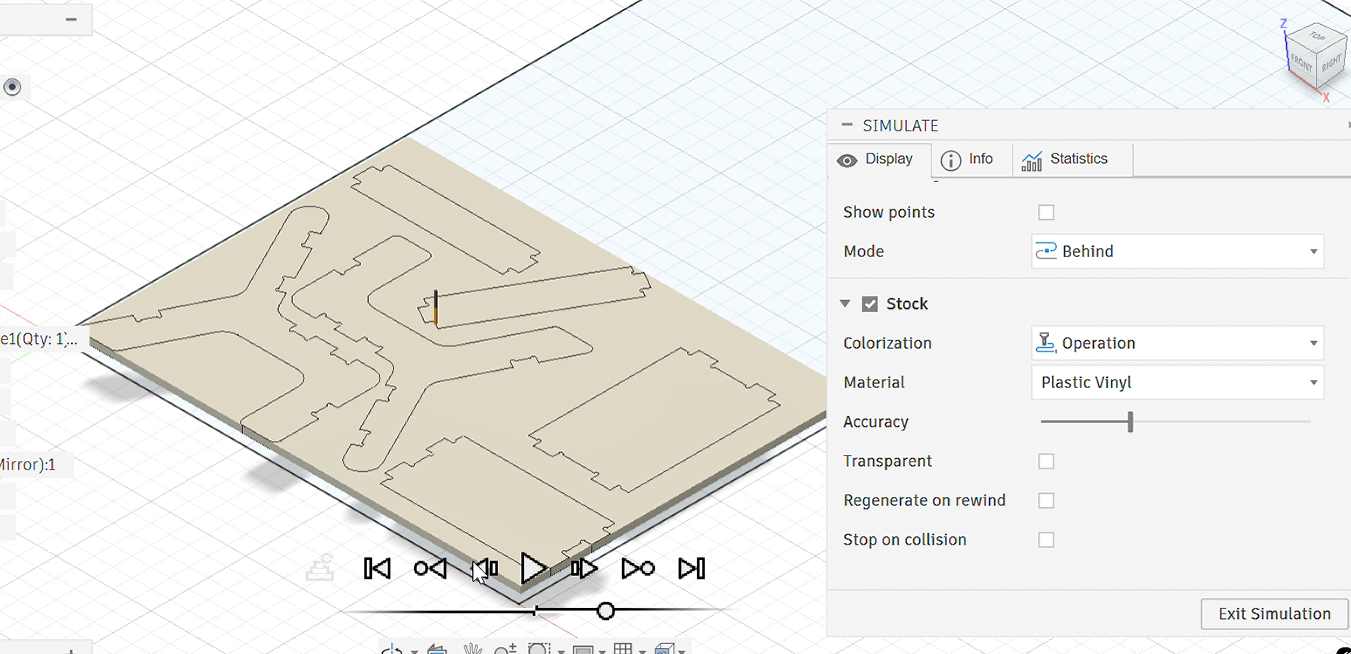
During the simulation, I enabled the Stock option to visualize how the tool interacts with the material. This helped confirm that all components were correctly cut and that there were no toolpath errors or collisions.
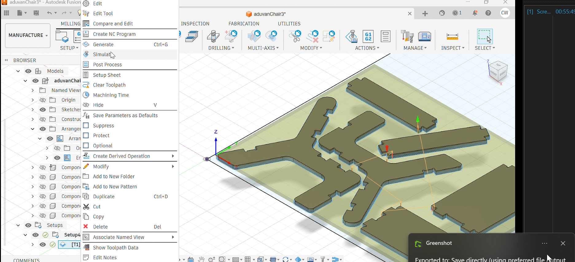
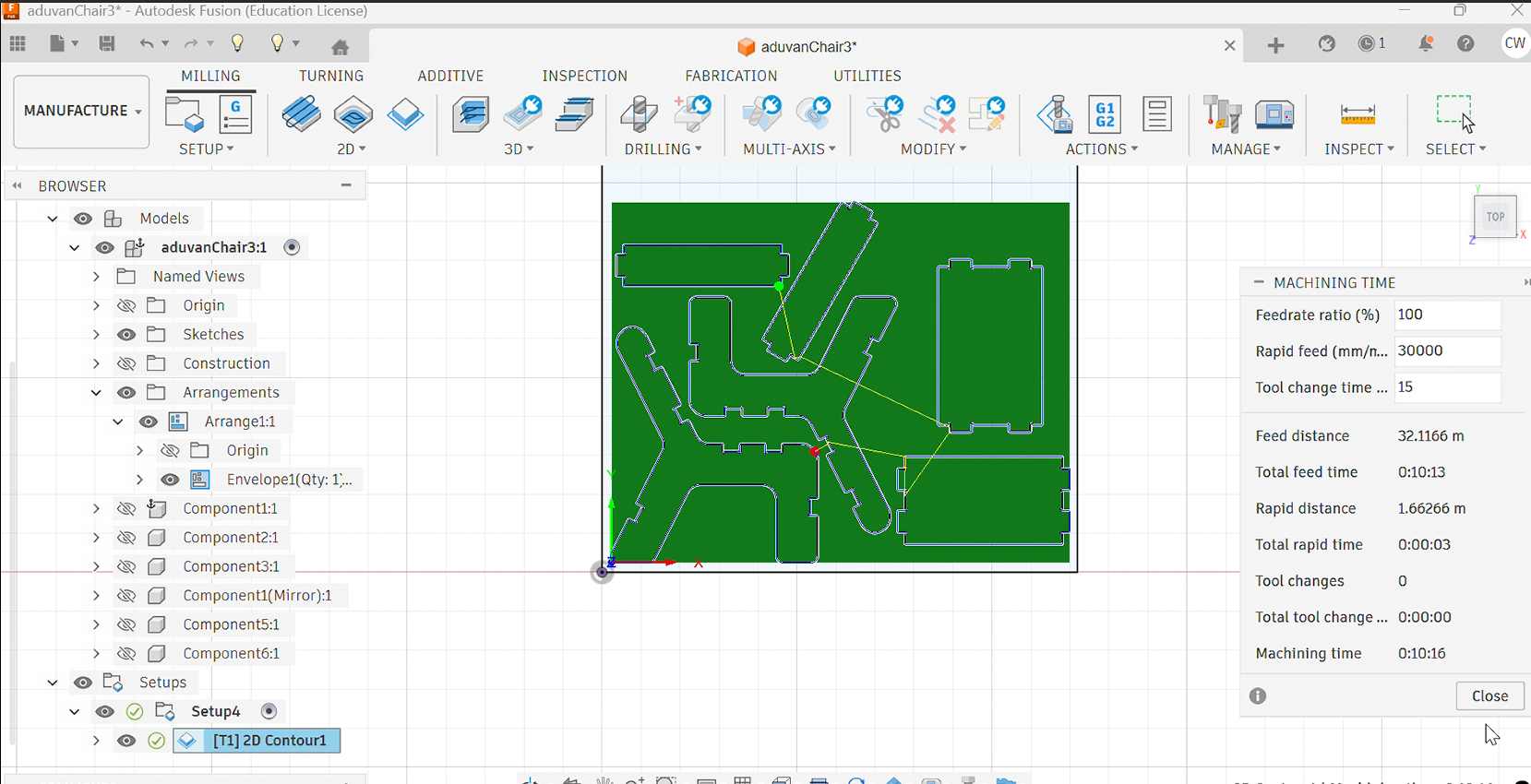
I also checked the estimated machining time, which provides an approximation of how long the CNC operation will take.
Post Processing and Export
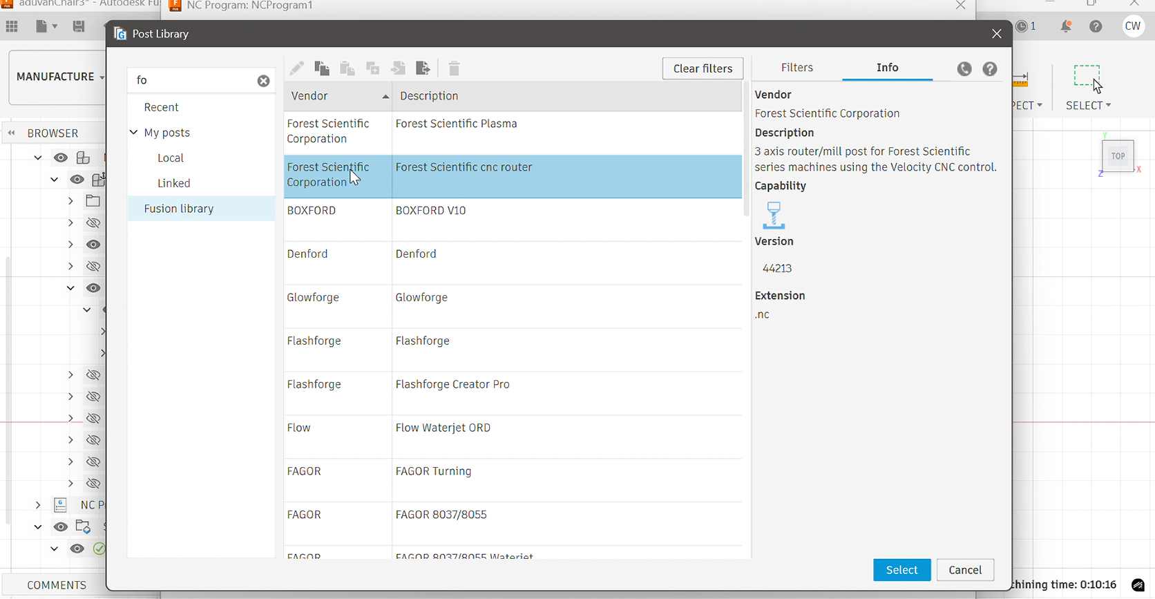
After confirming the toolpaths were correct, I generated the CNC machine file. In the Manufacture workspace, I selected Actions → Post Process.
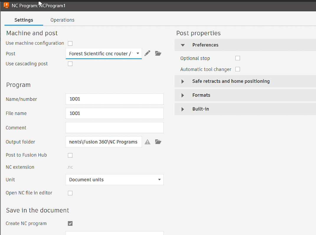
I ensured the correct post processor configuration was selected and set the Post Location to Local. The output file was then generated and saved as 100.NC, which is a standard G-code file used by CNC machines.
This file is now ready to be loaded into the Velocity CNC control software, where it will be used to execute the cutting process on the machine.
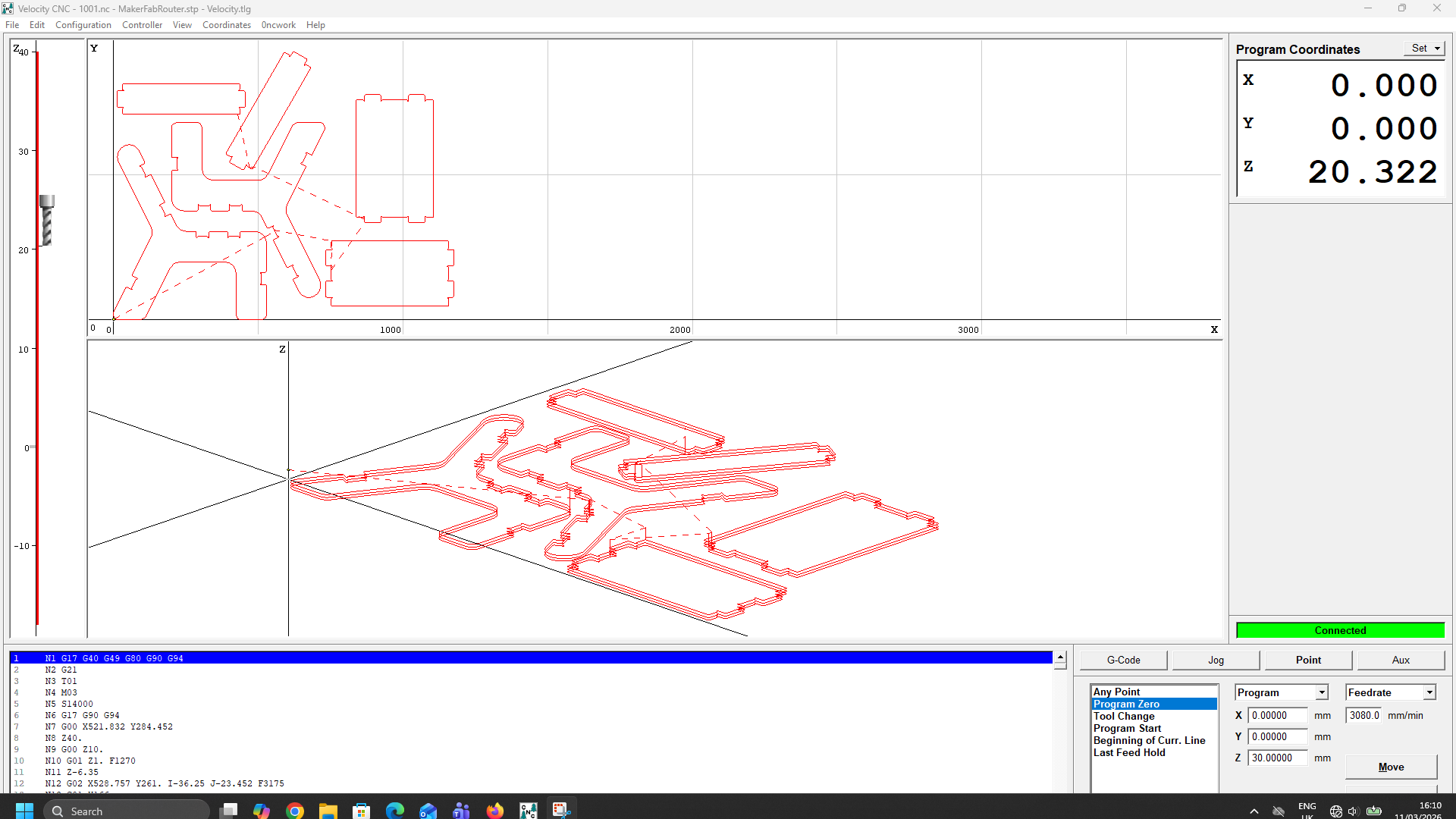
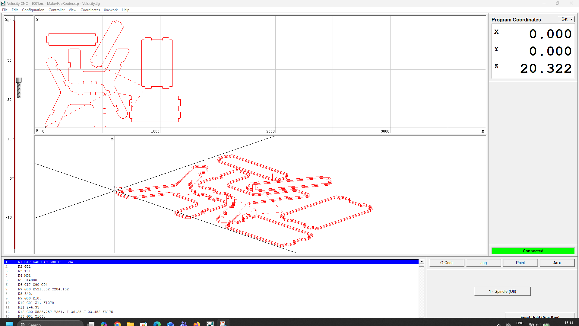
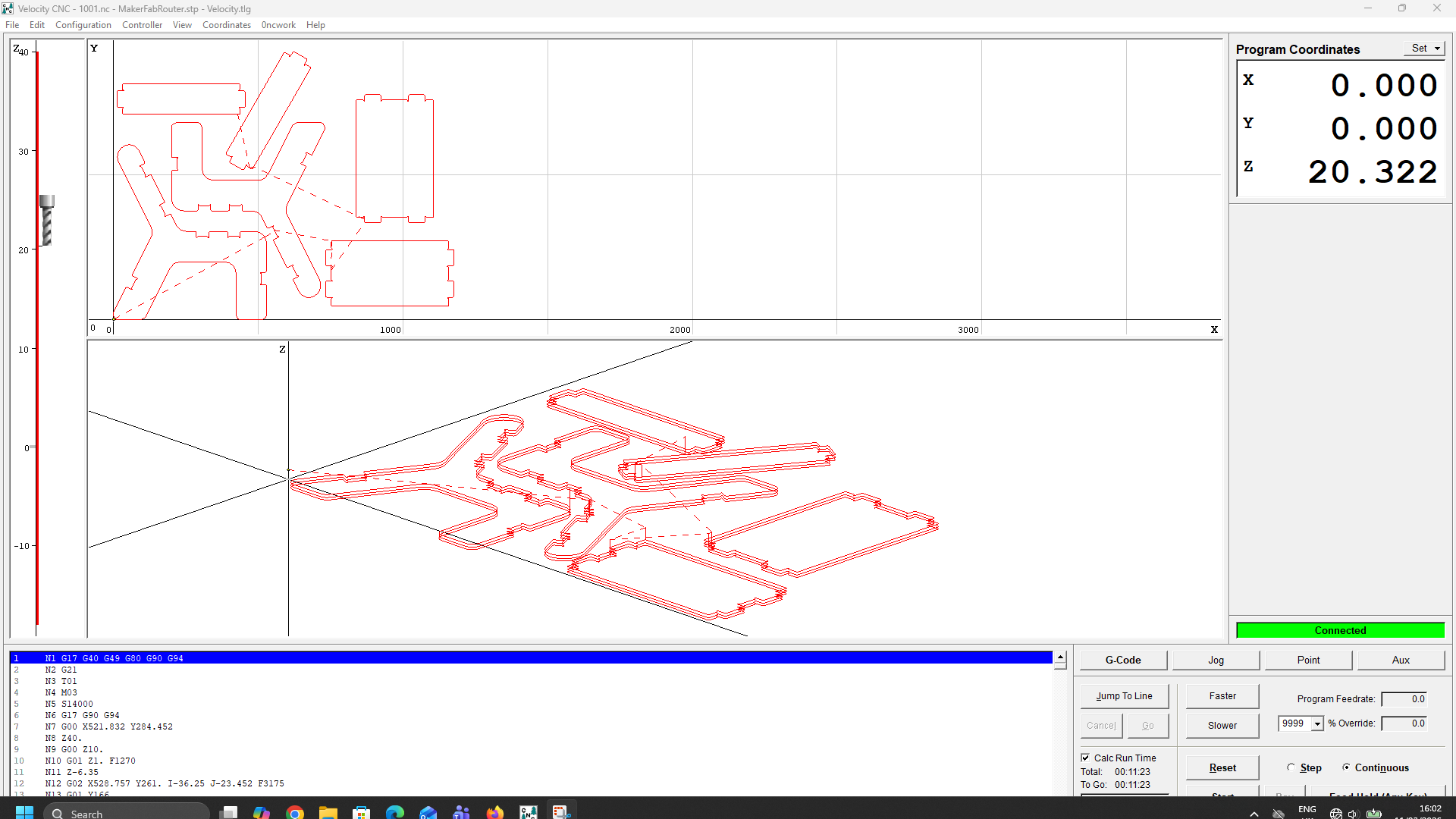
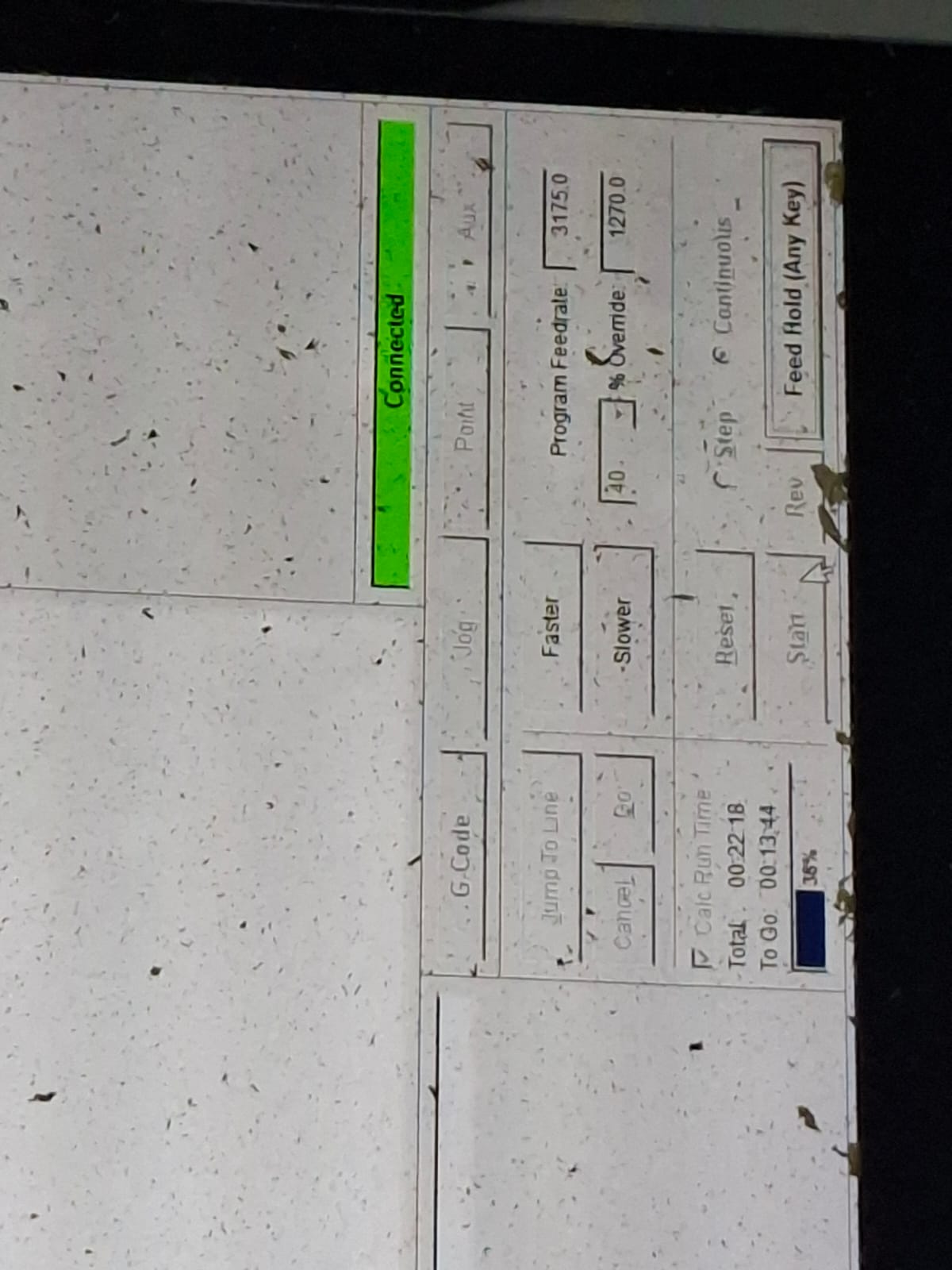
Veloctiy CNC Control To perform the cutting operation, I used the Velocity CNC control software to run the CNC machine. First, I imported the G-code file (100.NC) generated from Fusion 360 into the Velocity CNC software.
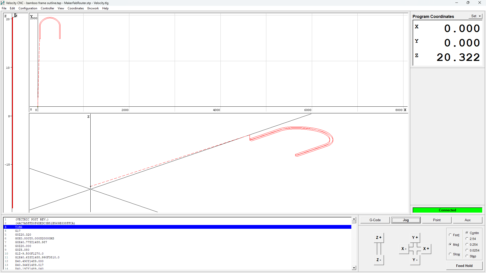
After loading the file, I prepared the machine by jogging the CNC spindle to the starting position. Jogging allows manual control of the machine to position the tool correctly before cutting. Using the jogging controls, I slowly moved the spindle to the desired starting point on the material and set the X and Y coordinates as the origin.
Once the spindle was positioned correctly, I zeroed the machine coordinates to define the reference point for the cutting operation. Zeroing ensures that the CNC machine follows the toolpaths relative to the correct starting position. I set the X and Y zero positions at the selected starting corner of the material. The Z-axis was zeroed on the surface of the material, ensuring that the cutting depth is measured accurately from the top surface of the sheet, as shown in the image.
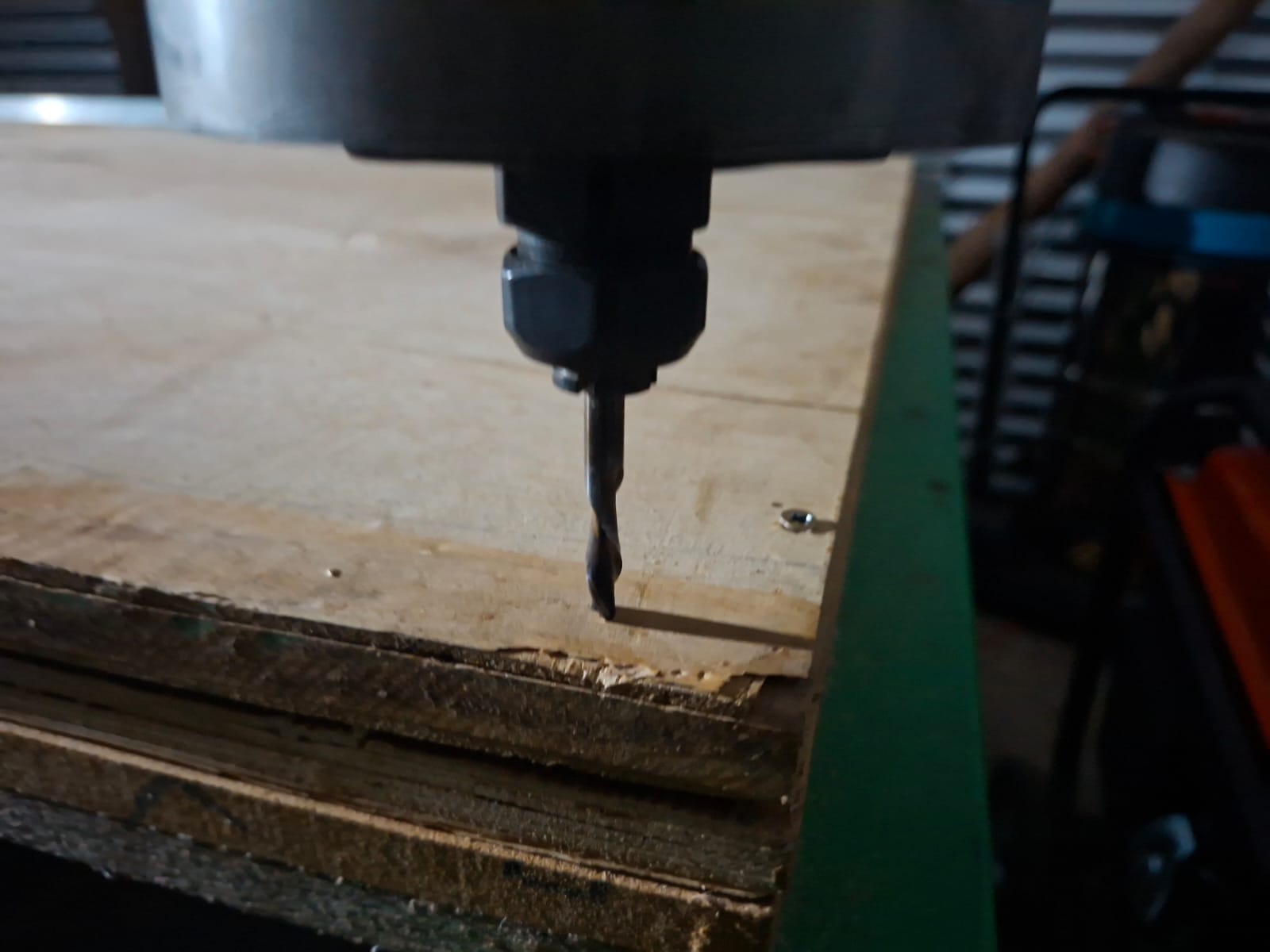
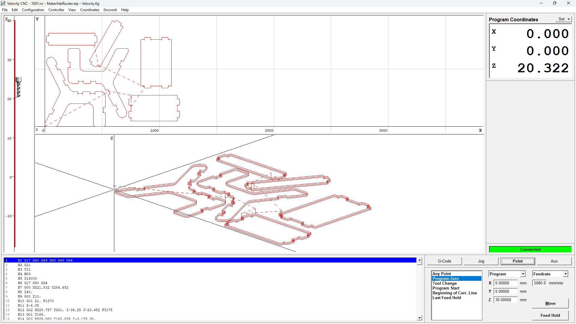
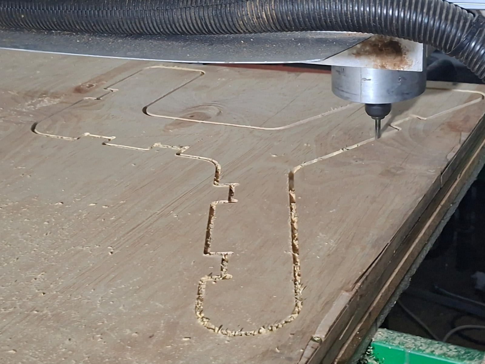
After setting the origin, the machine was ready to begin the cutting process. I then started the spindle, which initiated the machining operation according to the generated toolpaths. It took 22mins 14 seconds to cut.
## Assembly Process
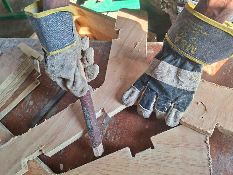
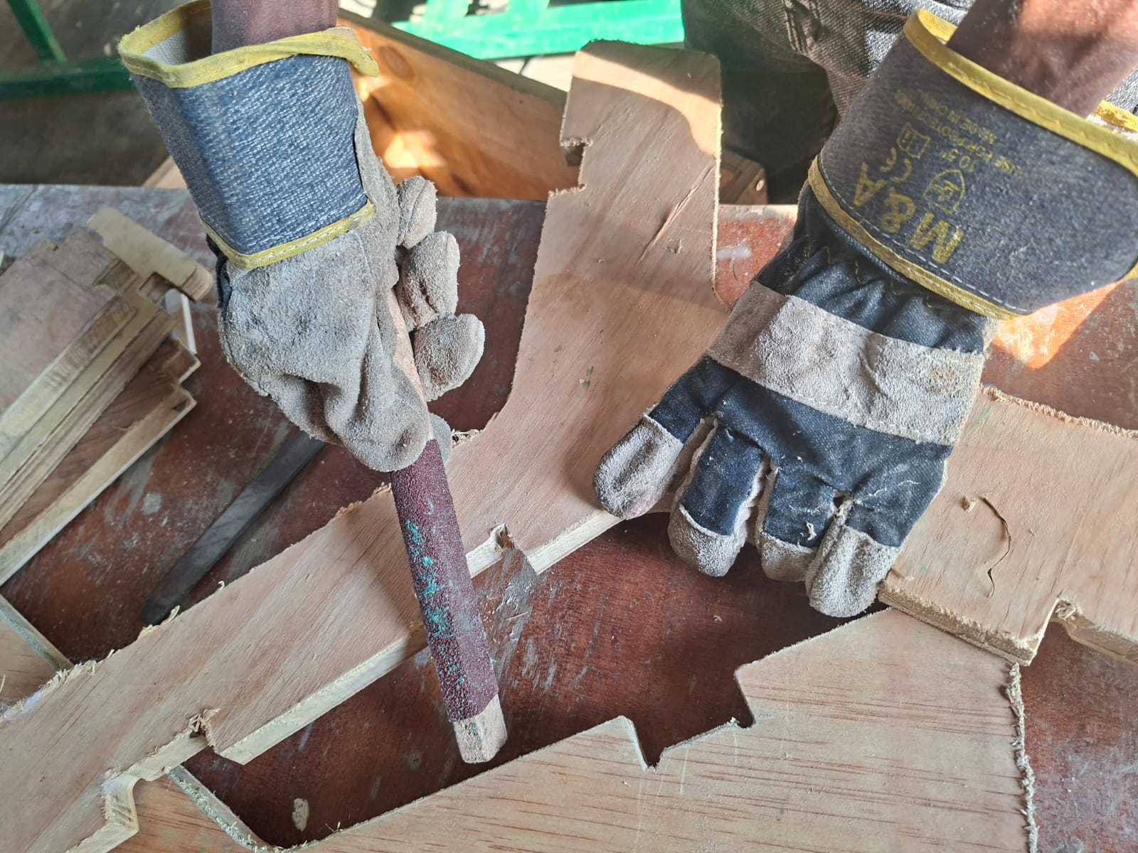
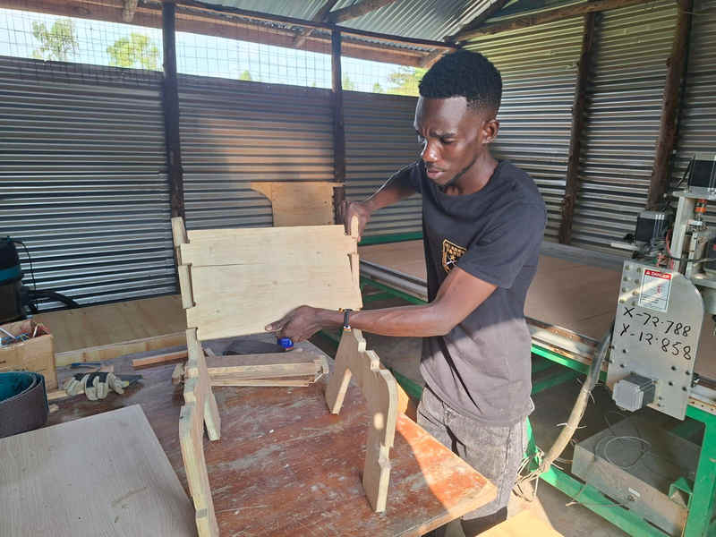
After the CNC machining process was completed, the parts were removed from the plywood sheet and the remaining tabs were trimmed off. The edges were lightly sanded to improve the fit and finish.
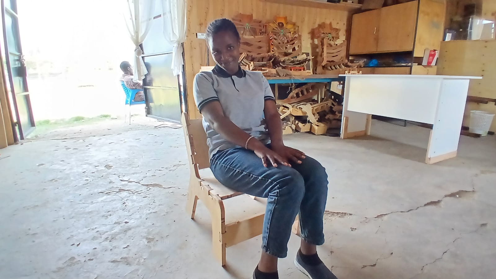
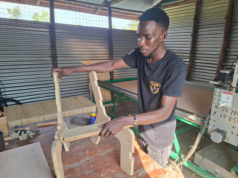
The chair was assembled using press-fit joints designed in Fusion 360. The dogbone fillets added during the design stage allowed the joints to fit correctly despite the round profile of the milling cutter.
Assembly Steps
- Remove all parts from the plywood sheet.
- Trim and sand the tabs.
- Align the slots on the side frames, seat, and backrest.
- Press-fit the parts together.
- Verify that the chair is stable and properly aligned.
Learning Outcomes
Learning Outcomes
- Learned how to create a parametric design using Fusion 360.
- Learned how to use user parameters to control design dimensions.
- Learned how to create and apply dogbones for CNC machining.
- Generated and simulated CNC toolpaths using the Manufacture workspace.
- Learned how to export G-code and prepare files for CNC machining.
- Operated the Velocity CNC software and set machine origins.
Design File
The design files used for this assignment are attached below: