5. 3D Scanning and printing
group assignment:
• test the design rules for your 3D printer(s)
individual assignment:
  • design, document, and 3D print an object
     that could not be made subtractively
     (small, few cm3, limited by printer time)

  • 3D scan an object (and optionally print it)
For this week, the group assignment was to test the design rules of our 3D printer. This involved checking tolerances, minimum wall thickness, overhang limits, and clearances between moving parts. These tests helped us understand the physical limitations of our printer and informed the design decisions for the individual assignment.
Group Assignment
Individual Assignment
For the individual assignment, I designed and 3D printed an object that cannot be made subtractively and cannot be assembled after fabrication. The object is a ball enclosed inside a box. This design demonstrates the power of additive manufacturing because the ball is permanently trapped inside the box and can only be produced in a single print.
Designing the Object
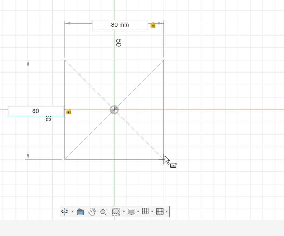
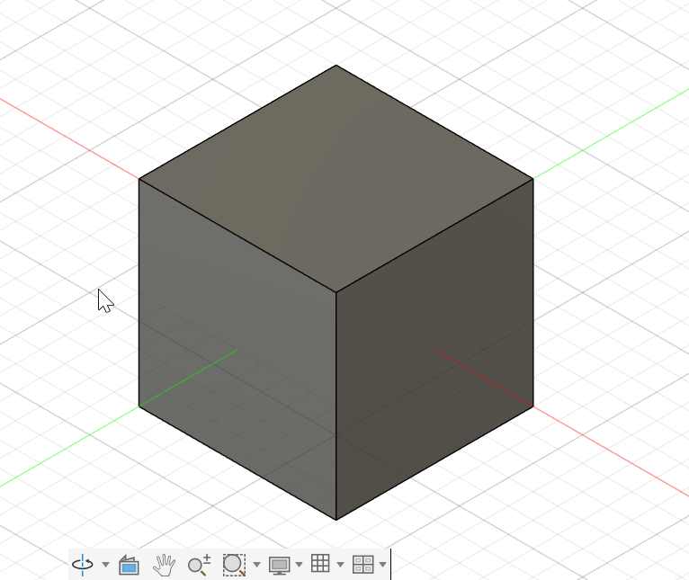
I began by creating a sketch on the front plane. Using the center rectangle tool, I drew a square with dimensions of 80 mm by 80 mm. This square formed the base profile of the cube.
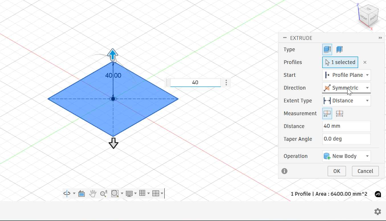
After finishing the sketch, I used symmetric extrusion with a distance of 40 mm. I chose symmetric extrusion instead of one-sided extrusion because it pushes material equally in both directions from the sketch plane. This keeps the cube perfectly centered at the origin. Since I extruded 40 mm on each side, the total depth became 80 mm, forming a complete cube. Keeping the cube centered makes the revolve operation precise and balanced.
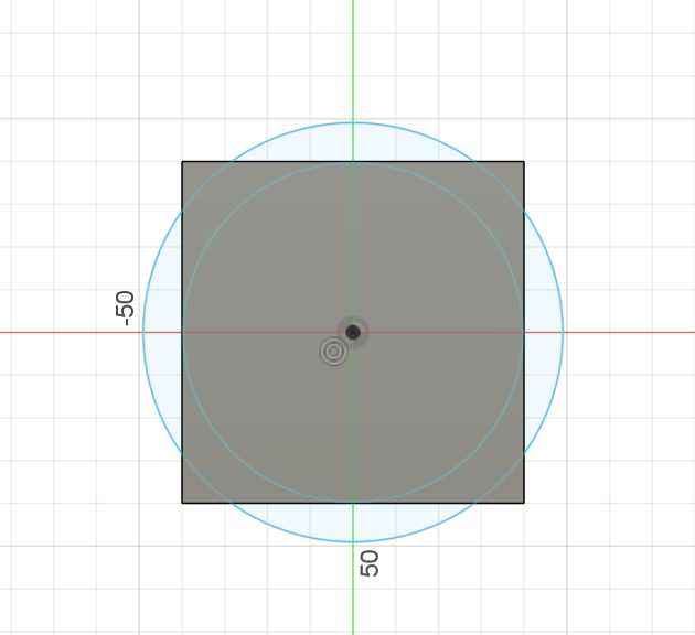
Next, I created a new sketch on the top face of the cube. I drew two center circles: one with a diameter of 97 mm and another with a diameter of 80 mm. The larger circle was designed to intersect the cube corners, while the smaller circle touched the middle of the cube’s sides. The reason for creating two circles was to define the outer curved cavity and the inner sphere.
I then drew a vertical construction line along the Y-axis. This line was important because it would serve as the axis of revolution. The revolve tool requires both a profile and an axis to create 3D rotational geometry.
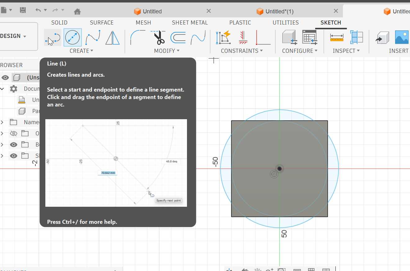
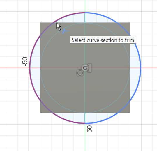
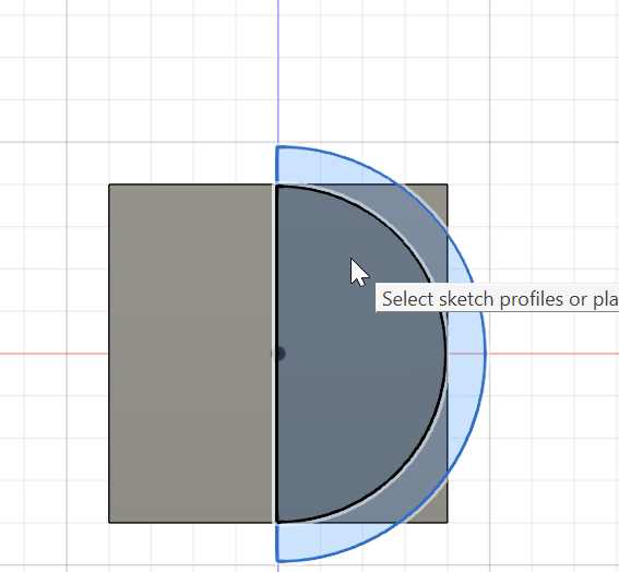
Using the trim tool, I removed half of both circles. I did this because the revolve tool works on a closed profile. By trimming half of the circles, I created clean half-circle profiles that could be rotated around the axis to form smooth spherical geometry.
I selected the outer half-circle profile and revolved it 360 degrees around the Y-axis. This operation created the curved internal cavity and circular openings on the cube’s faces. The revolve operation was necessary because it generates smooth spherical geometry, which cannot be achieved using simple extrusion.
 axis,
axis, 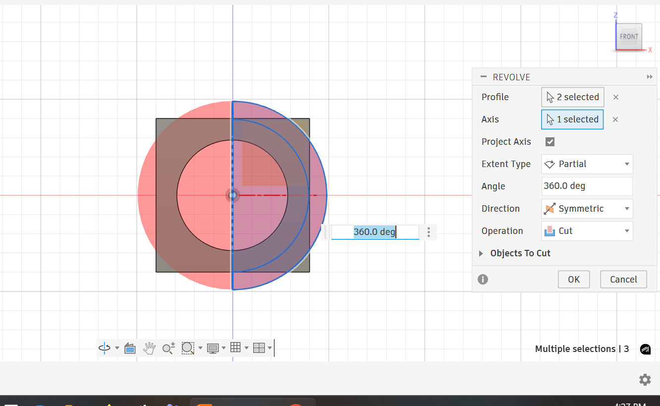
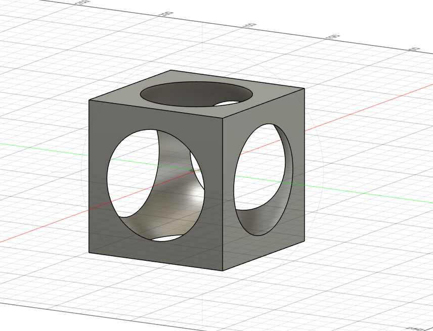
This is how it looks like after revolve, you can see there are circle holes in all sides of the square box.
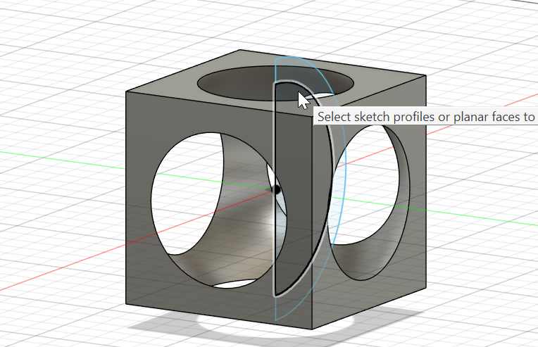
To create the internal sphere, I selected the inner half-circle profile,just enabled the second sketch to see it and revolved it 360 degrees around the same axis. This formed a complete ball inside the cube. Because the sphere was created within the enclosed geometry, it became permanently trapped.
The final result is a cube with circular openings on all sides and a fully enclosed internal sphere. The ball is free to move but cannot be removed without breaking the cube. This object cannot be manufactured using subtractive processes like milling, and it cannot be assembled after fabrication. It demonstrates the advantage of additive manufacturing.
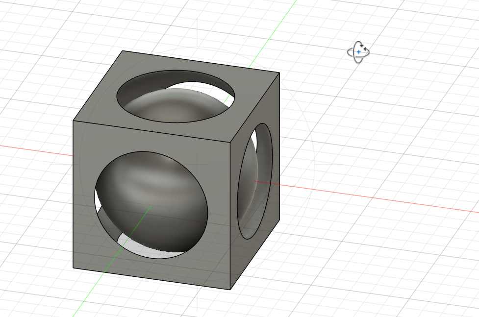
After completing the design in Fusion 360, I exported the file as an .STL file. I chose the STL format because it is the standard file type used for 3D printing. STL converts the solid model into a mesh made of small triangles, which slicing software can interpret and convert into machine instructions.
Slicing using -Prusa Slicer
I then opened PrusaSlicer to prepare the file for printing. In PrusaSlicer, I switched to Expert Mode. I chose Expert Mode because it gives access to all advanced printing parameters such as layer height, infill, supports, and print speeds. Even if I did not modify many settings, working in Expert Mode allows better control and understanding of the slicing process.
I clicked the Add button and imported the STL file from my folder. The model appeared on the virtual print bed.
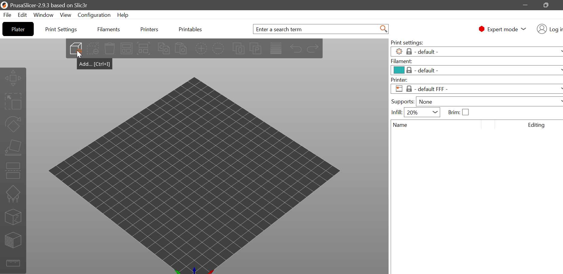 At this stage, I checked the orientation and size. The slicer allows scaling, but I kept the original dimensions since they were already correct and within the printer’s build volume.
Next, I clicked Slice Now. Slicing converts the 3D model into layers and generates the toolpaths the printer will follow. This step also shows estimated print time and material usage.
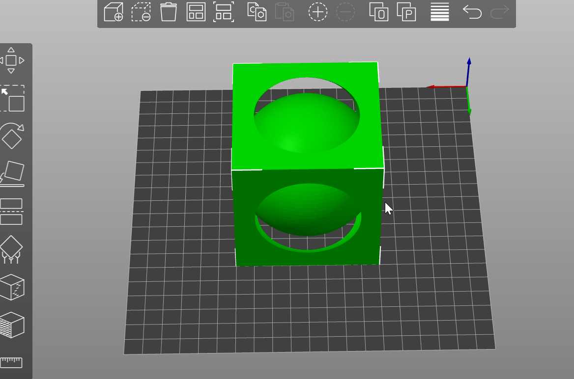
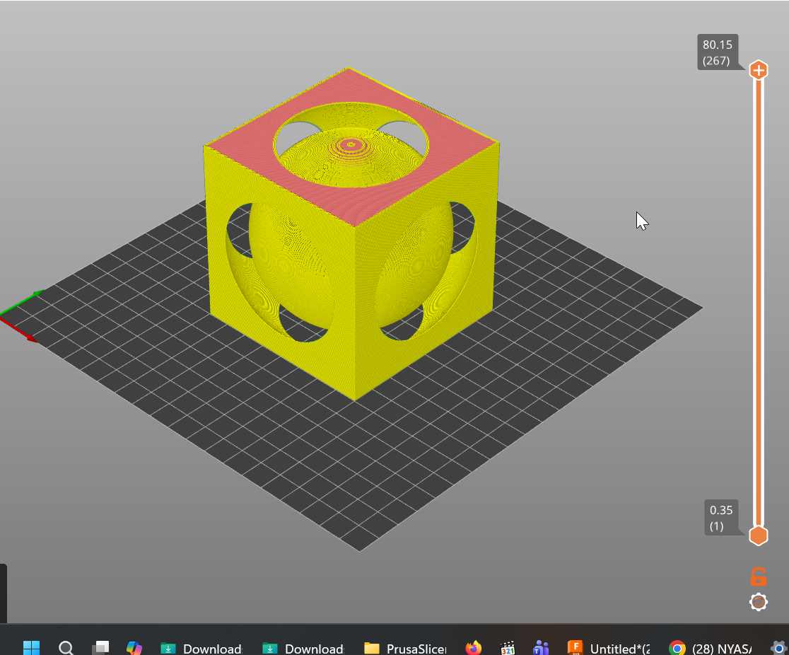
After slicing, I exported the file as G-code. The G-code contains the machine instructions for the printer. I then transferred this file to the 3D printer for fabrication.
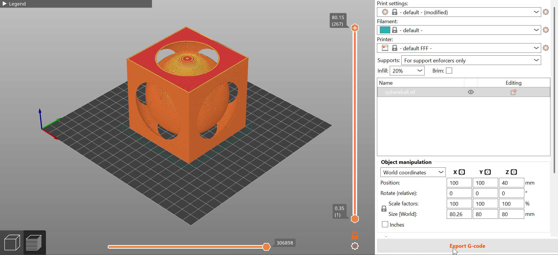
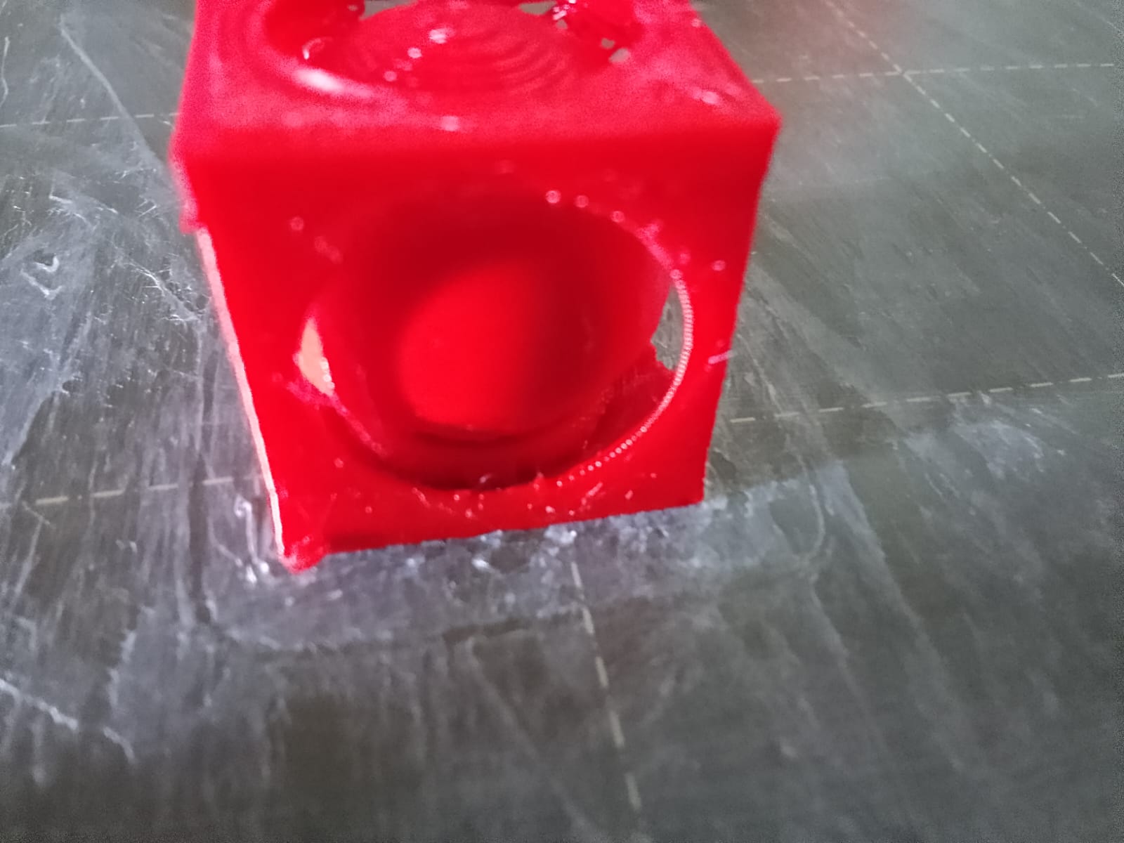
During my first 3D print attempt, I used the original design dimensions as modeled in Fusion 360. However, I experienced a bed adhesion problem. The print started normally, but after a few layers, the inner circle detached from the print bed. Once it became loose, the nozzle dragged the part around, which damaged the entire object. I attempted the print several times, but the same issue kept occurring. The problem was likely due to poor bed adhesion and the small surface area of the inner circle, which reduced its contact with the build plate.
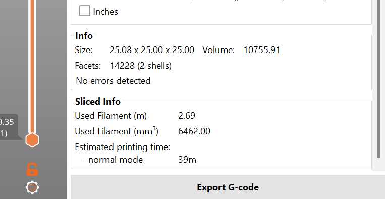
To solve this issue, I decided to resize the model directly in PrusaSlicer and reduced the overall size to 31 mm. While preparing the new print, I set the infill to 20% . 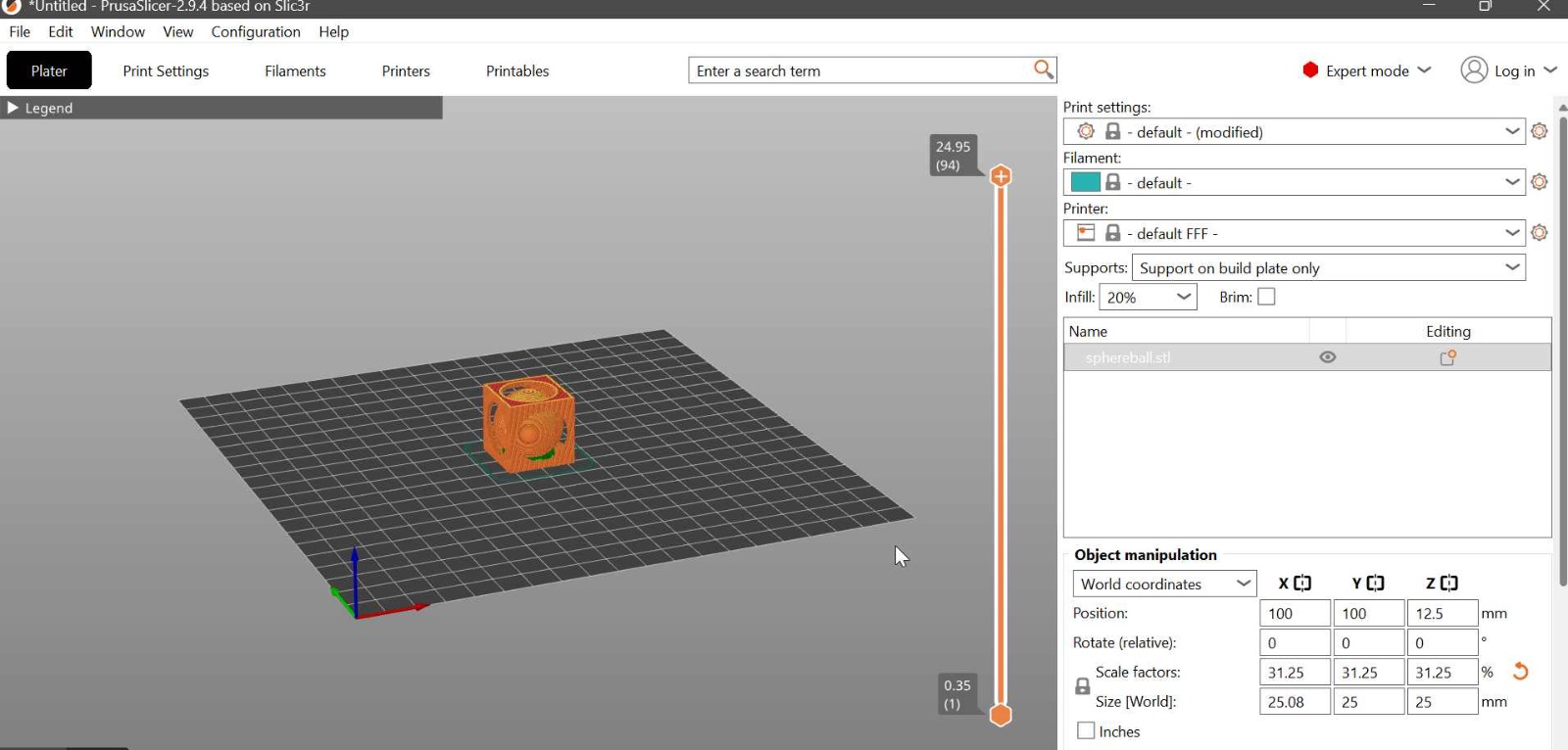 The estimated print time was approximately 39 minutes. After scaling it down and confirming the slicing parameters, I reprinted the object. This time, the part adhered properly to the bed and completed successfully without detachment or layer shifting.
3D Scanning
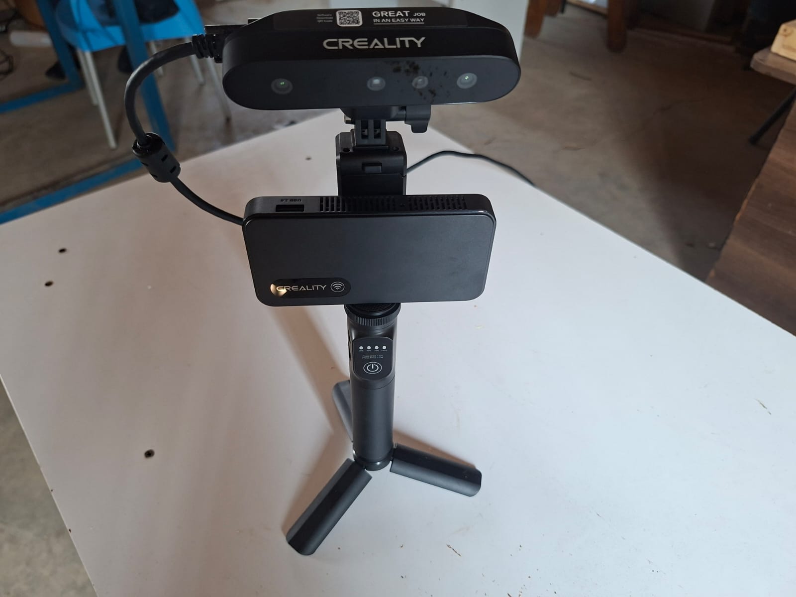
For this assignment, I explored 3D scanning as a method of capturing a real-world object and converting it into a digital model that could later be processed and 3D printed. I used the Creality CR-Scan Ferret Pro to scan a digital multimeter and recreate it as a printable 3D model.
The Creality CR-Scan Ferret Pro is a portable handheld 3D scanner designed for scanning small and medium-sized objects. It supports marker, geometry, and texture tracking modes and can capture models with relatively high accuracy while remaining easy to carry around. Its compact size made it suitable for scanning objects within the Fab Lab environment.
The object I selected for scanning was a digital multimeter.
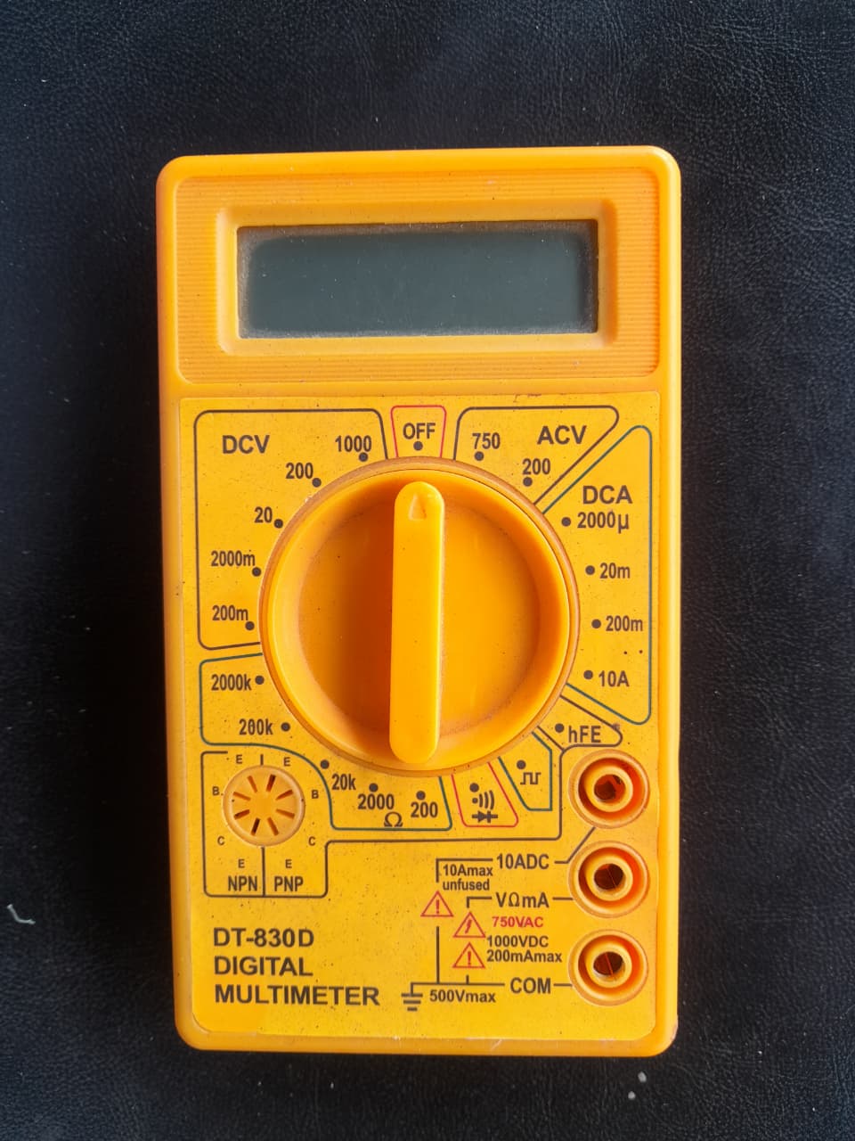
The multimeter contains several flat surfaces and repetitive features that can make it difficult for the scanner to continuously track its position during scanning. To improve tracking accuracy, I placed marker dots on the multimeter. These markers provide unique reference points that help the scanner determine its location relative to the object, reducing the chances of losing tracking while capturing different sides of the model.
BODIES/OBJECTS USING CREALITY SCAN
To begin, I connected the scanner to the computer and launched the Creality Scan software. Communication between the scanner and the software was established through the scanner hotspot connection.
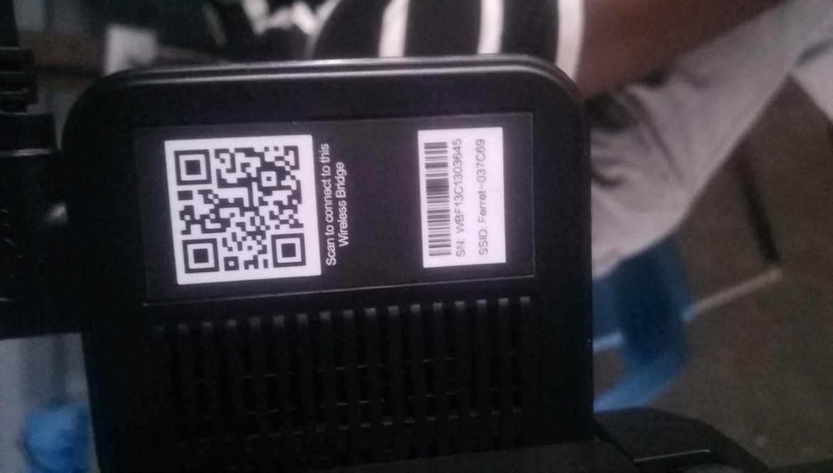
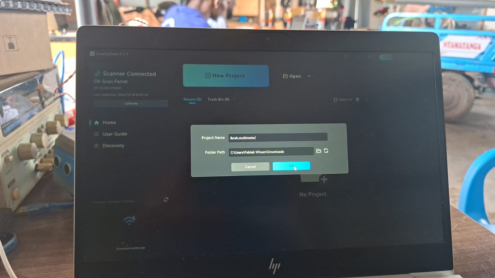
After connecting successfully, I created a new project and entered the project information. Creating a dedicated project helped keep all scan data, meshes, and processed files organized in a single location.
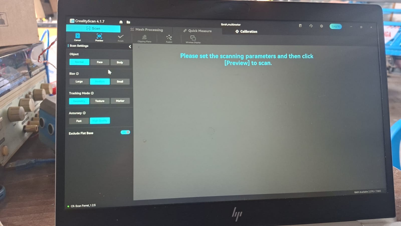
Next, I configured the scan settings according to the object being scanned. Since the multimeter is a medium-sized object, I selected the appropriate object size and scanning mode. Because marker dots had already been applied to the surface, I chose Marker Tracking Mode. This allowed the scanner to use the markers as reference points and maintain stable tracking throughout the scan.
I also selected High Quality mode to capture more detail and enabled Exclude Flat Base to avoid collecting unnecessary data from the supporting surface.
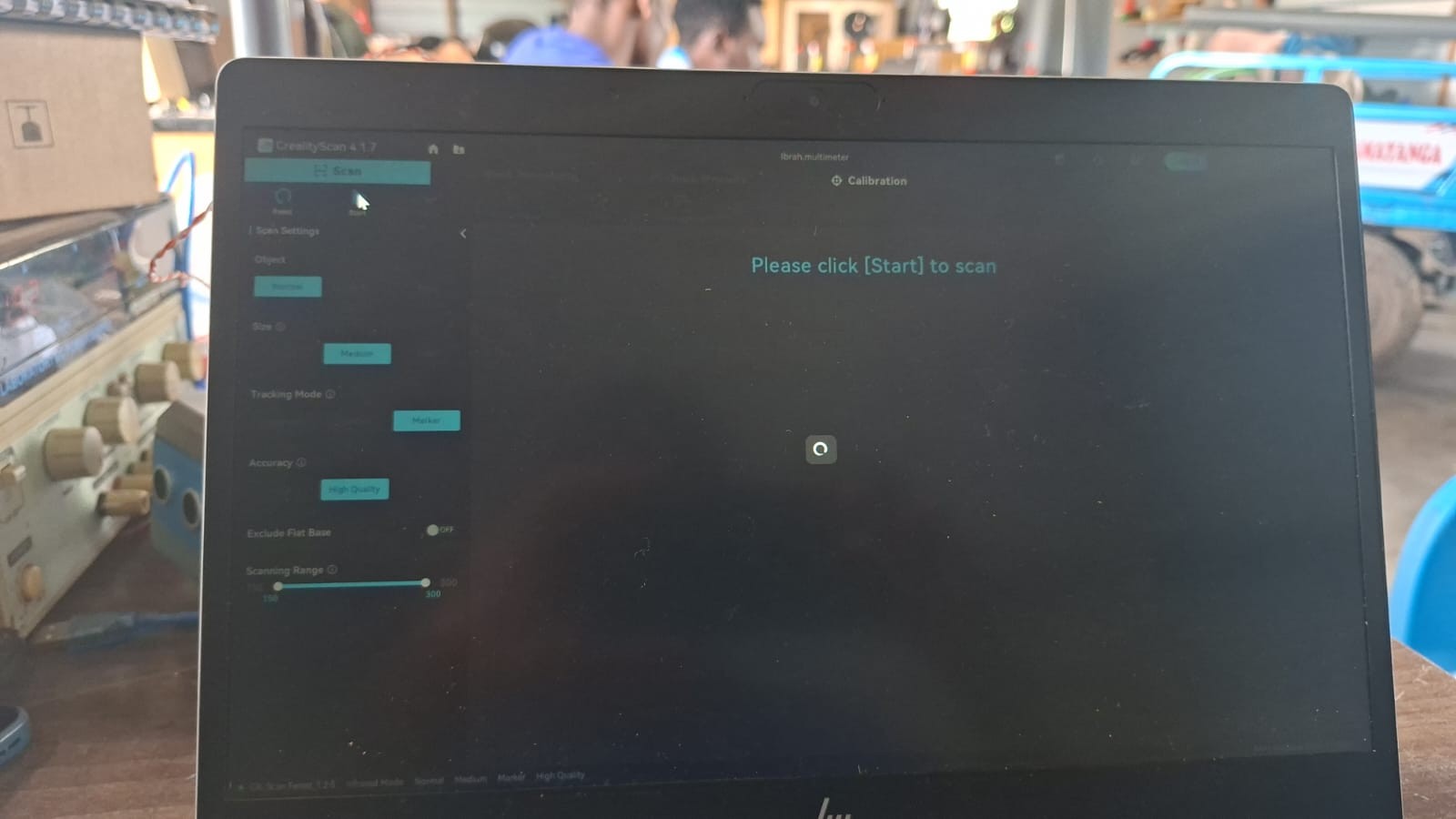
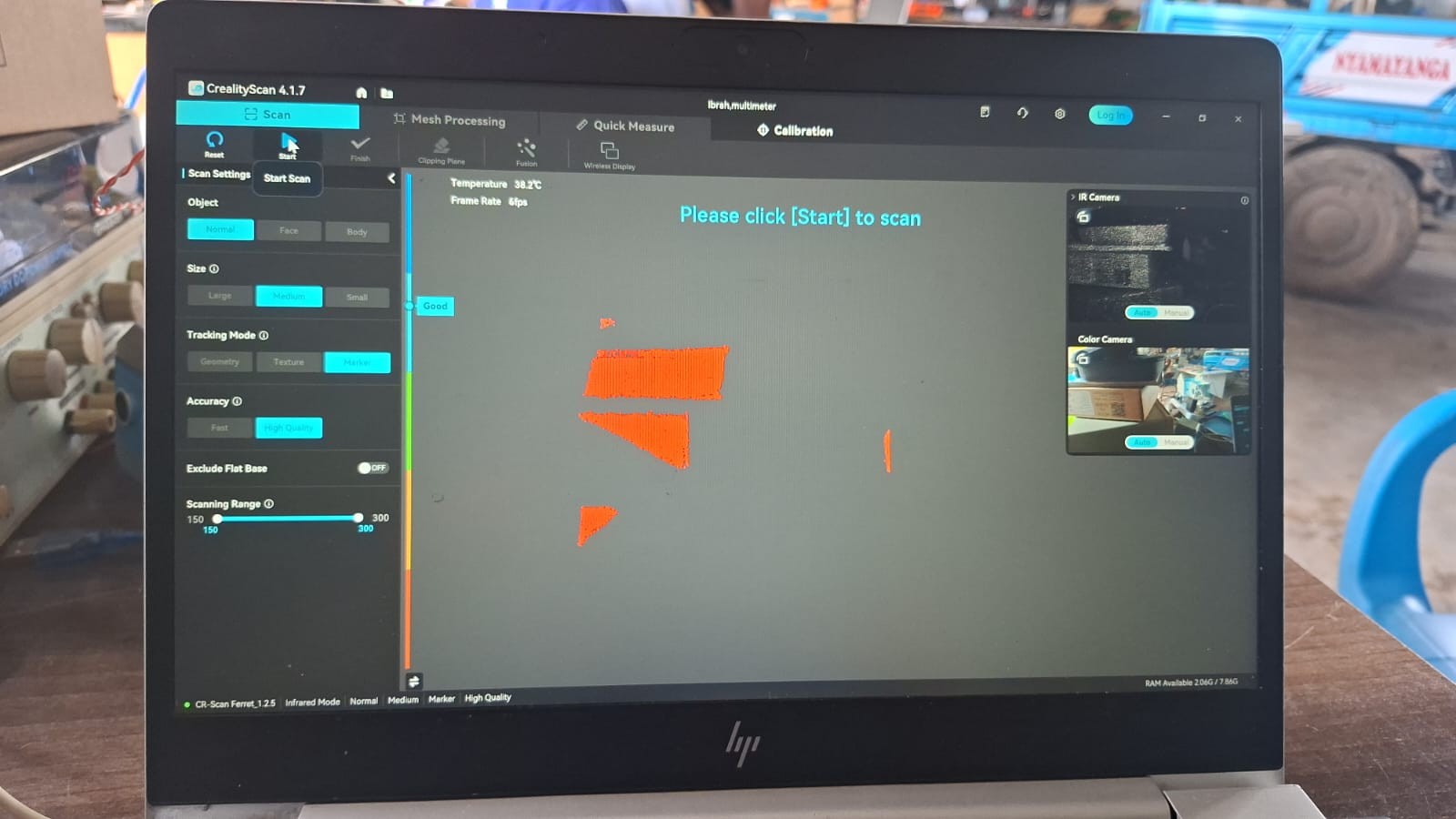
Before starting the actual scan, I performed a preview to verify that the scanner could clearly detect the object. During this stage, I observed that the software displayed a green indicator when the scanner was positioned at the correct distance from the multimeter. This helped ensure that the object would be captured accurately.
Once everything was ready, I started scanning and slowly rotated the multimeter so that all sides could be captured. The relationship between the scanner and the object was important throughout the process. The scanner remained focused on the multimeter while continuously tracking the marker dots, allowing the software to combine multiple viewpoints into a single 3D model.
During scanning, I made sure that movements were controlled and steady to avoid losing tracking. A useful addition to this documentation would be a photograph showing me holding the scanner while scanning the multimeter, since this demonstrates the actual scanning setup used during the assignment.
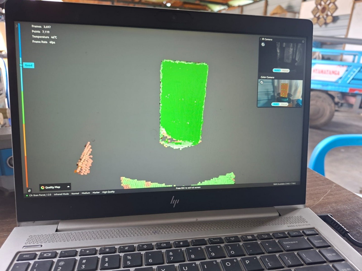
After completing the scan, the raw model contained some irregular surfaces and unwanted artifacts. To prepare the model for printing, I performed several mesh-processing operations directly within the Creality Scan software.
Mesh Processing
The first step was Simplify. This reduced the number of polygons in the mesh, making the file easier to process and export while still preserving the overall shape of the multimeter.
Next, I applied Smooth to reduce surface noise that appeared during scanning. This helped create cleaner and more consistent surfaces.
I then used Hole Filling to close gaps that occurred in areas where the scanner could not fully capture the geometry. Filling these holes produced a watertight model suitable for 3D printing.
Finally, I used Alignment to correctly position and orient the model. Proper alignment ensures that the object sits correctly within the digital workspace and later in the slicing software.
After these operations, the mesh represented a much cleaner version of the scanned object.
Color Mapping
To preserve the appearance of the original object, I performed color mapping. This process projected the captured color information onto the mesh surface.

Re-Meshing
After the initial mesh processing, I performed meshing again.
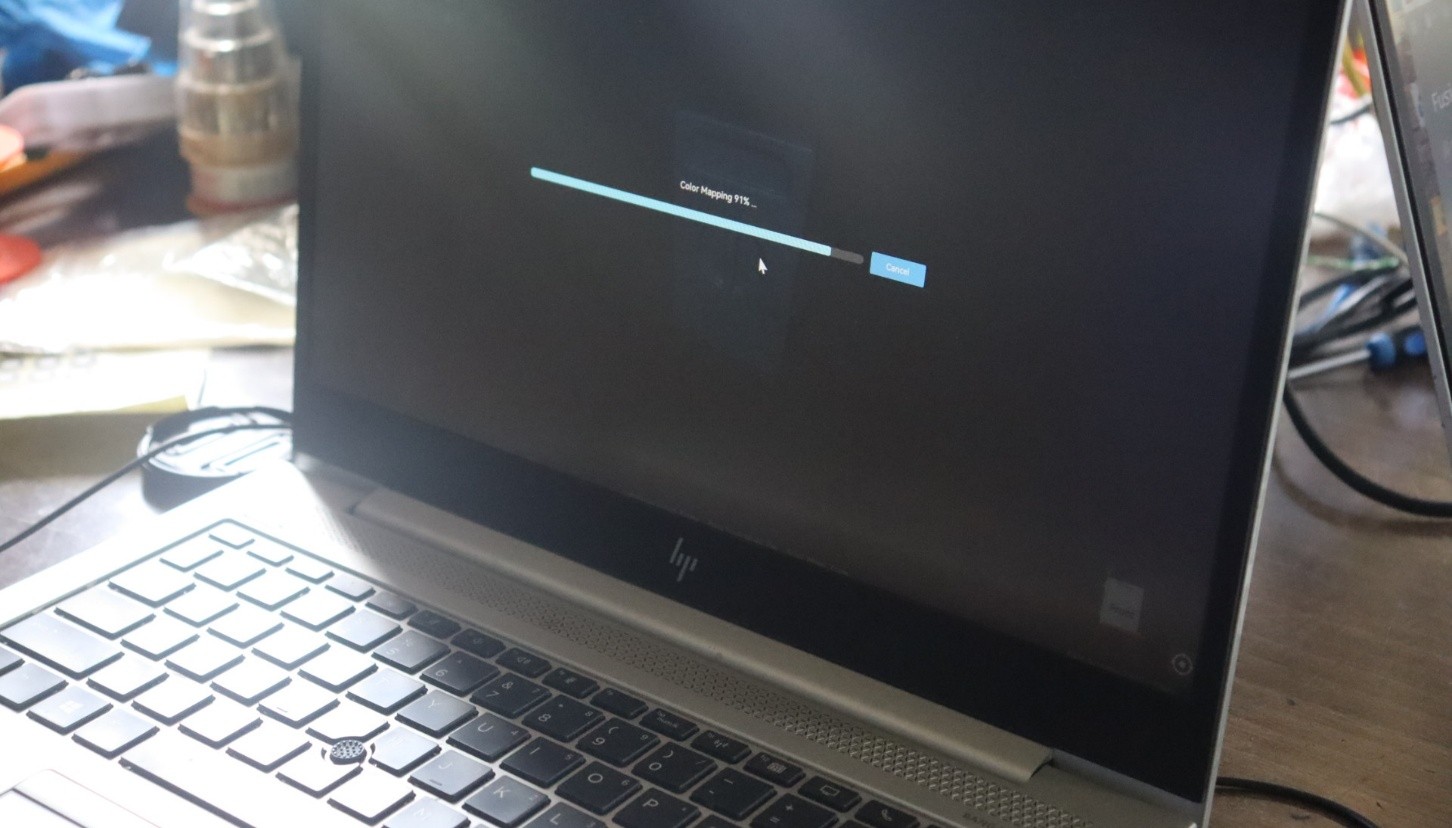
The mesh-processing operations and re-meshing were both performed within the same software environment. Re-meshing reorganizes the mesh structure and generates a cleaner, more uniform surface representation. This improves model quality, repairs remaining inconsistencies, and prepares the geometry for export.
Re-meshing is important because it creates a more reliable model for manufacturing. Without this step, the exported file may contain defects that could cause problems during slicing or printing.
After re-meshing, the model was ready to be exported as an STL (Standard Tessellation Language) file.
STL is commonly used in additive manufacturing because it represents the surface of a 3D object using triangular facets. Most slicing software, including PrusaSlicer, can directly interpret STL files and generate toolpaths for 3D printing.
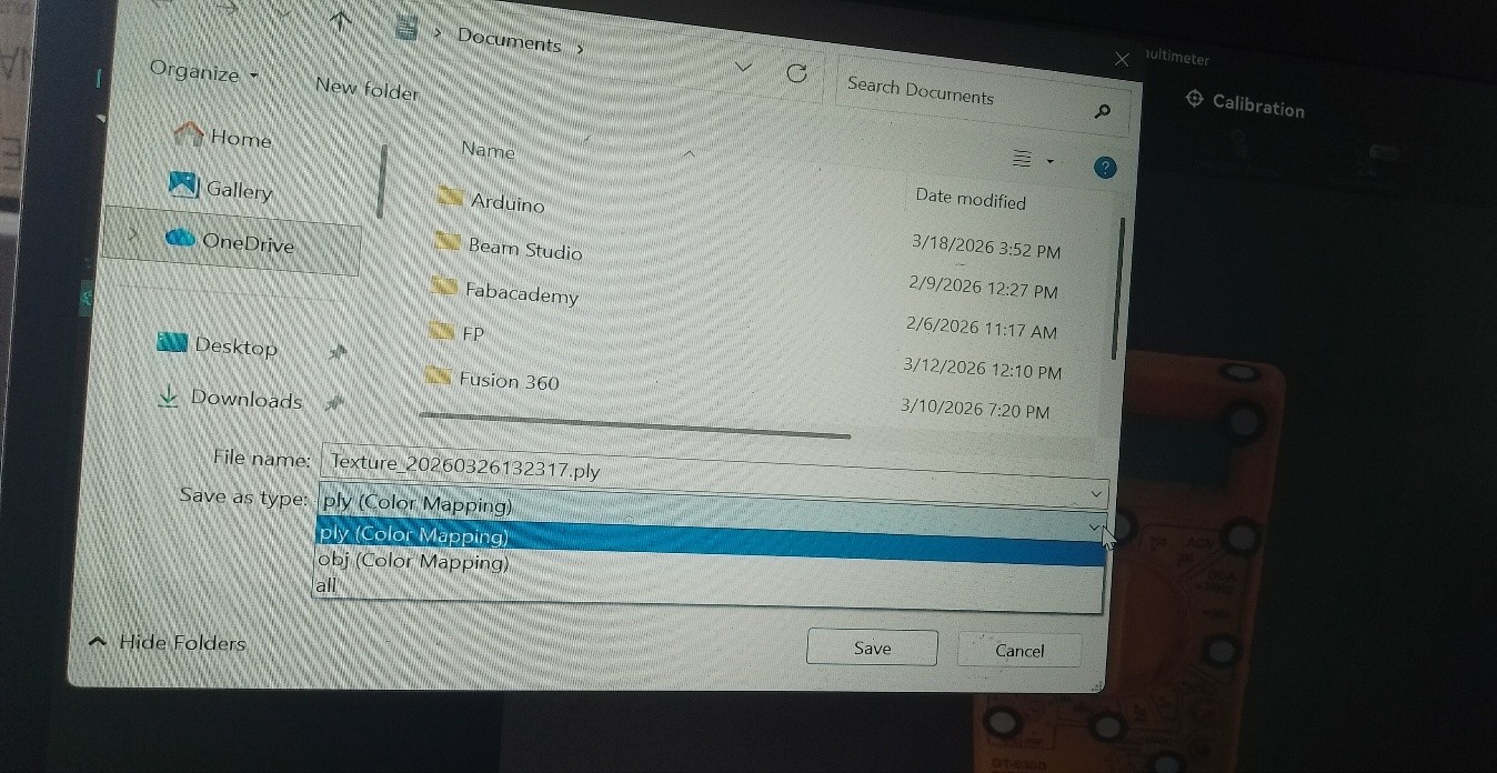
To generate the STL file, I selected Export Model, chose STL as the output format, and saved the file to the project folder.
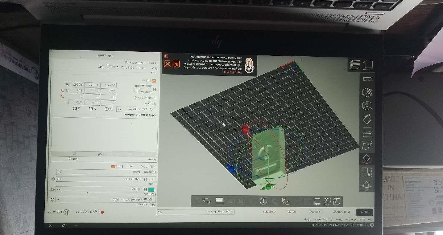
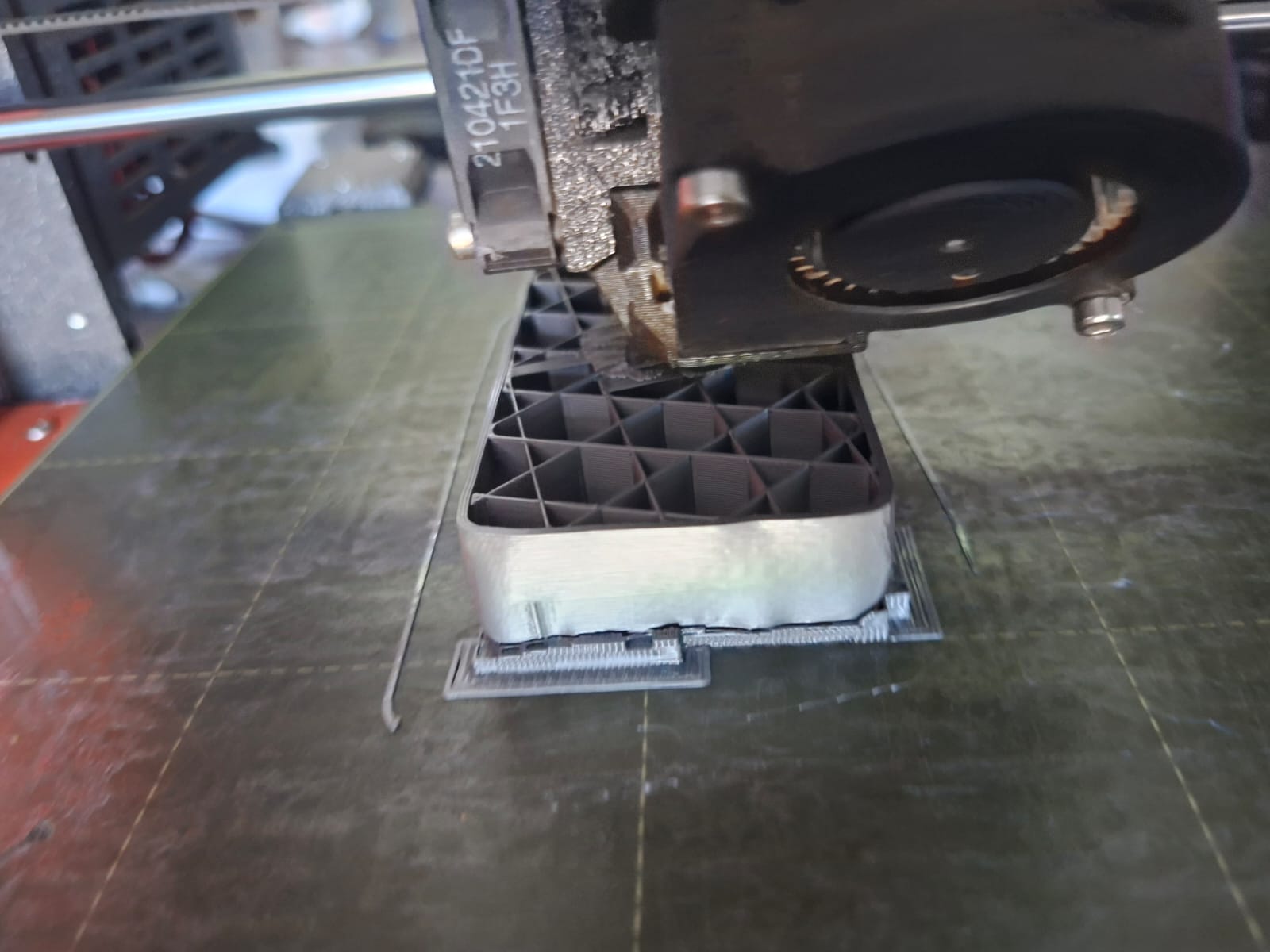
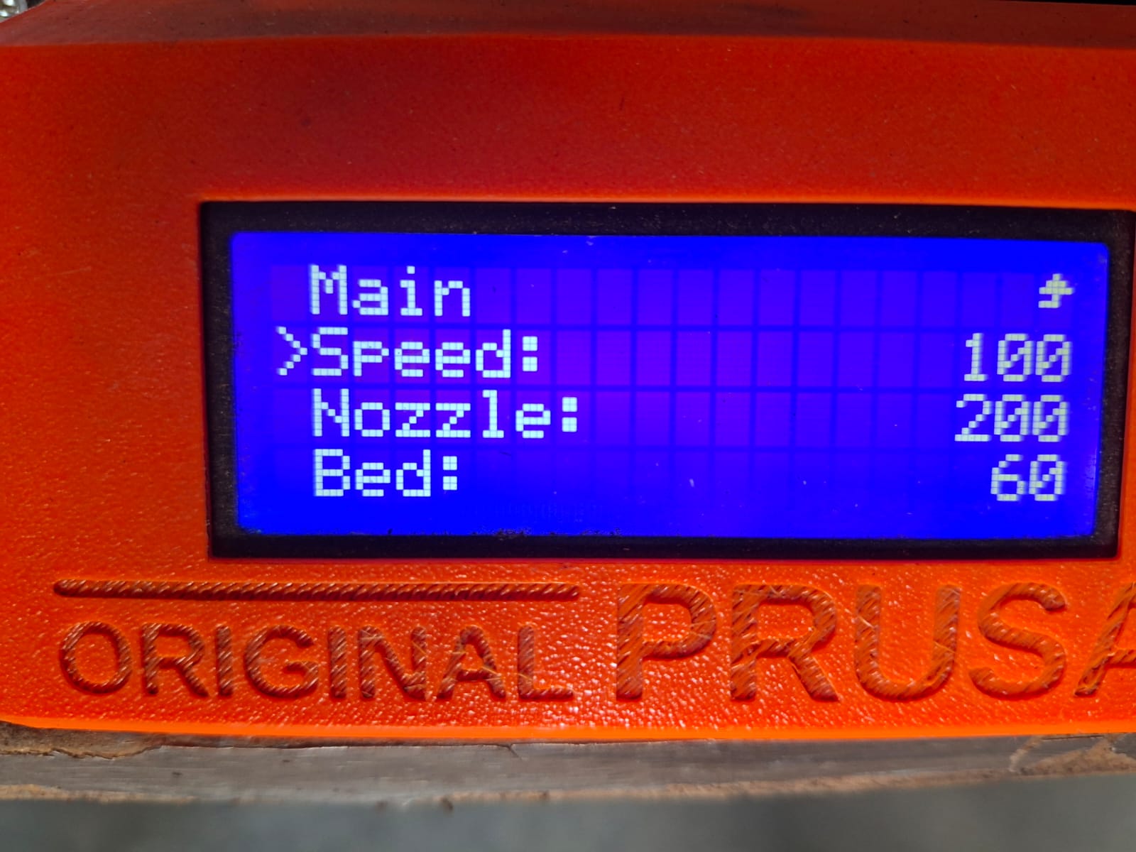
Finally, the STL model was imported into PrusaSlicer and prepared for printing. I printed the model using a nozzle temperature of 200°C, a bed temperature of 60°C, and a print speed of 100%.
Final Product
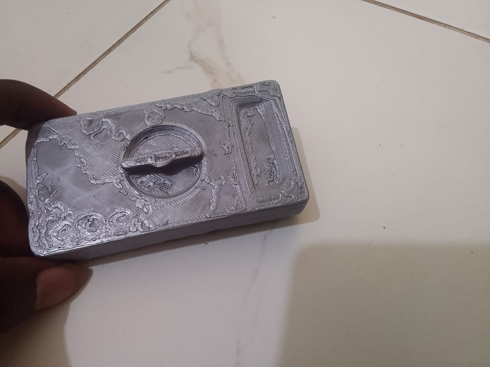
The printed model successfully reproduced the overall shape of the multimeter. Although some fine details were simplified during scanning and mesh processing, the result demonstrated the complete workflow from physical object to digital model and finally to a manufactured part.
Second Scan
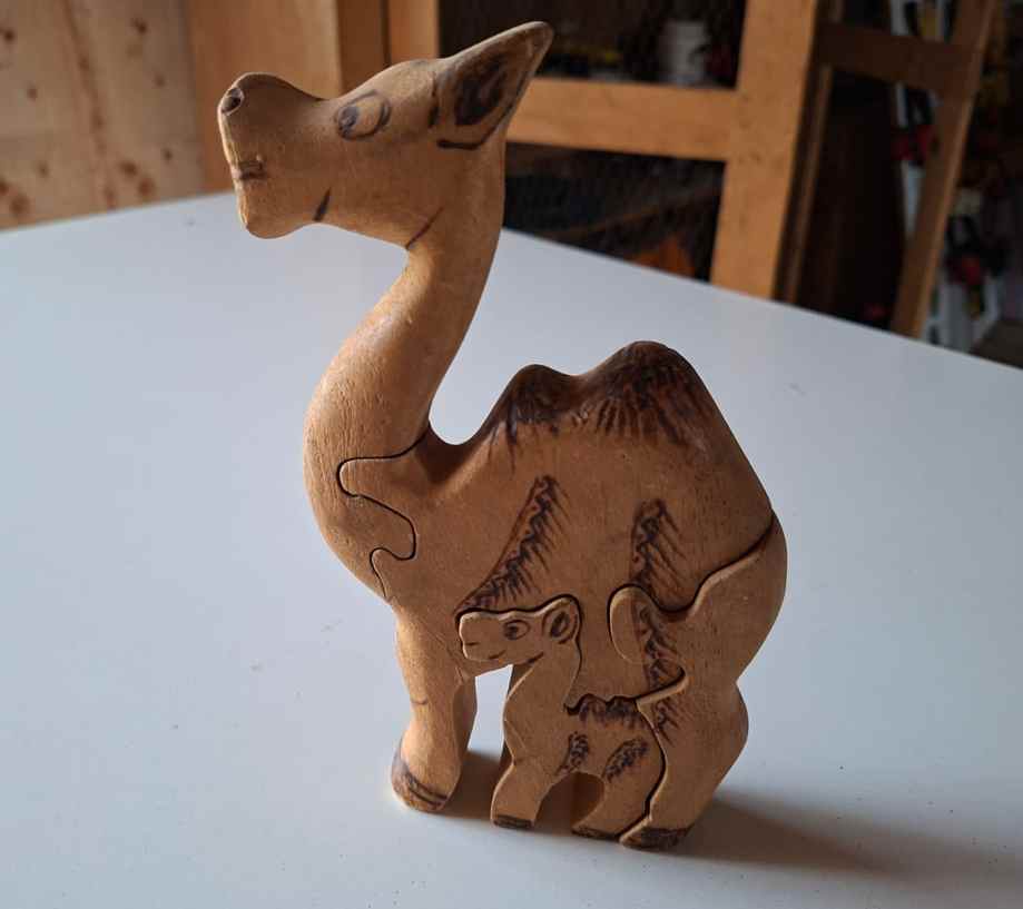
I changed my mind , and wanted to scan something real, that i can use,
Girrafe
Scanning Preparation.
Before scanning, i connected using the cable and not over the wifi,
I placed the object, to a rotating stand and now i was rotting it to ensure i scan both sides of my object.
Before i started scanning I clicked new scan then preview, and ensured that i was at the green region, once I mantained the green region now i cliked “start scan”,. After several scans whic were enough scan, I cliked finish, and now I had my object with scatered regions.
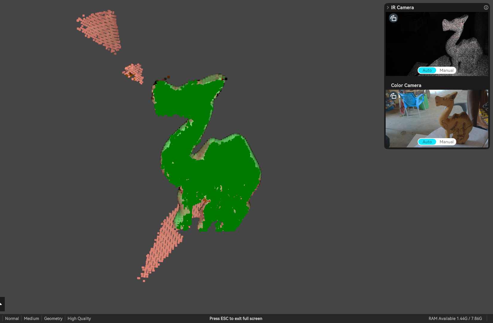 During scanning I made sure, the IR camera was showing my full object and also my camera object was intact as I mantain the green region.
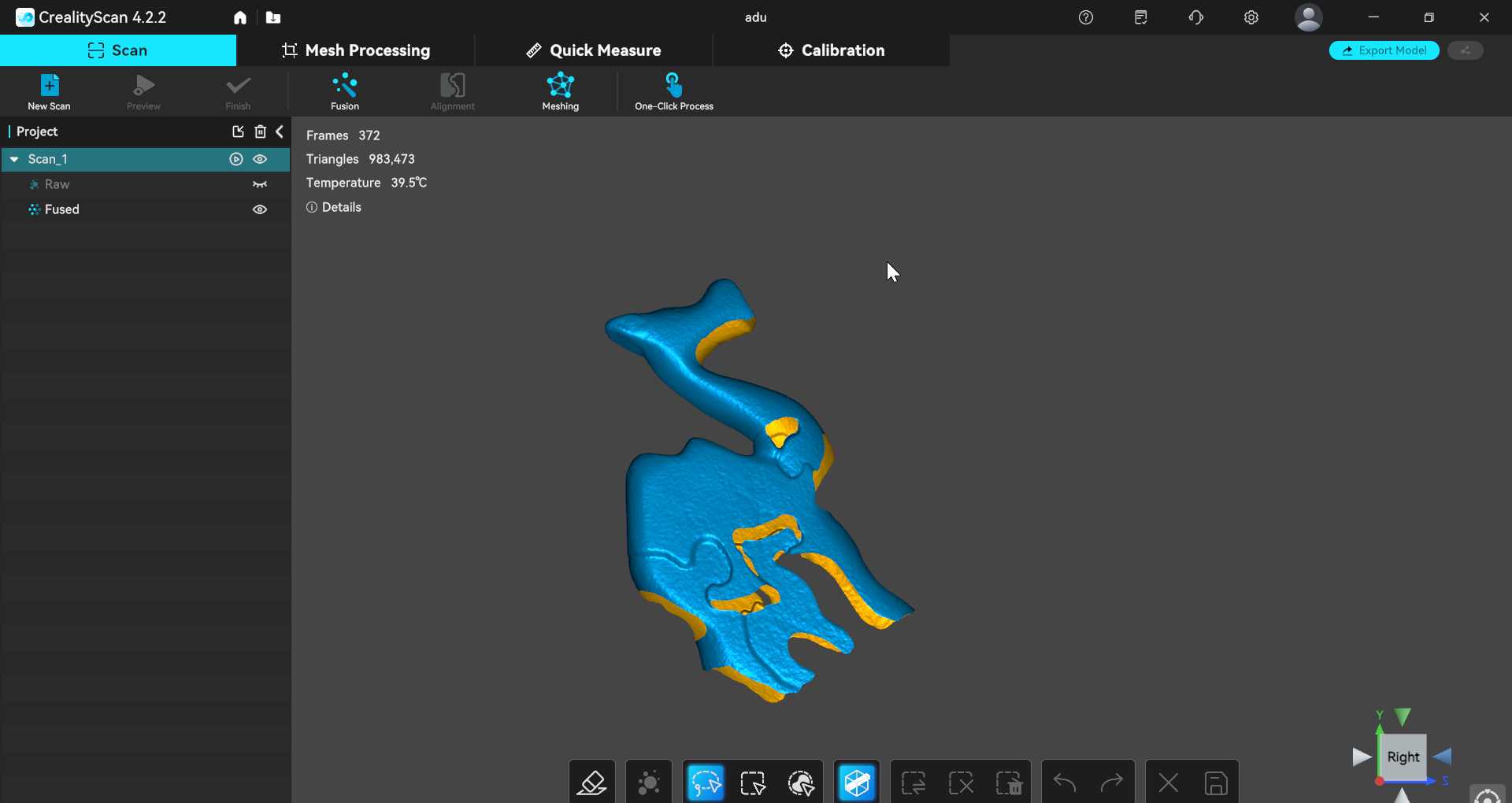
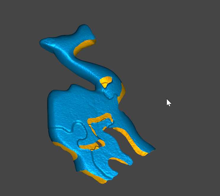
After fininsh the object shows you the temperature, triangles and frames. And you can see my scanned object has alot of holes whch i must work on to achieve a solid scan.
## Meshing Process
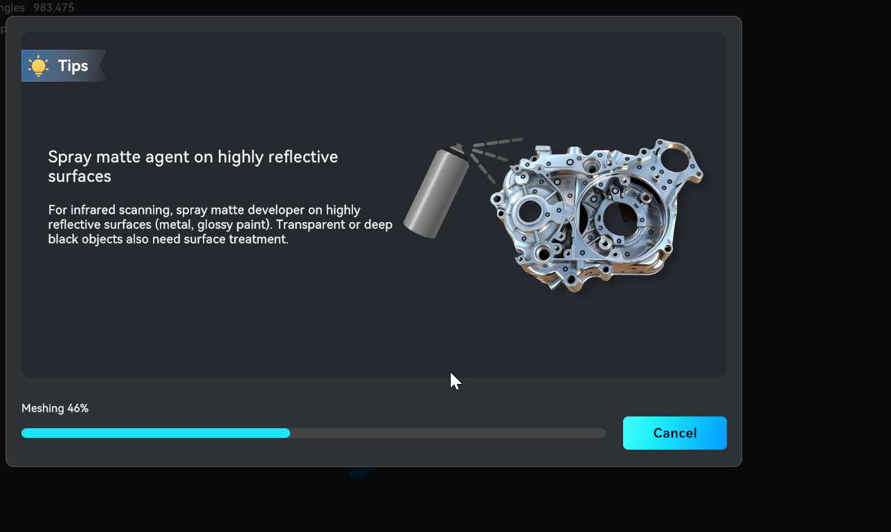
Under meshing, we have multi futures that ensures you come up with a real outcome,
Holefill
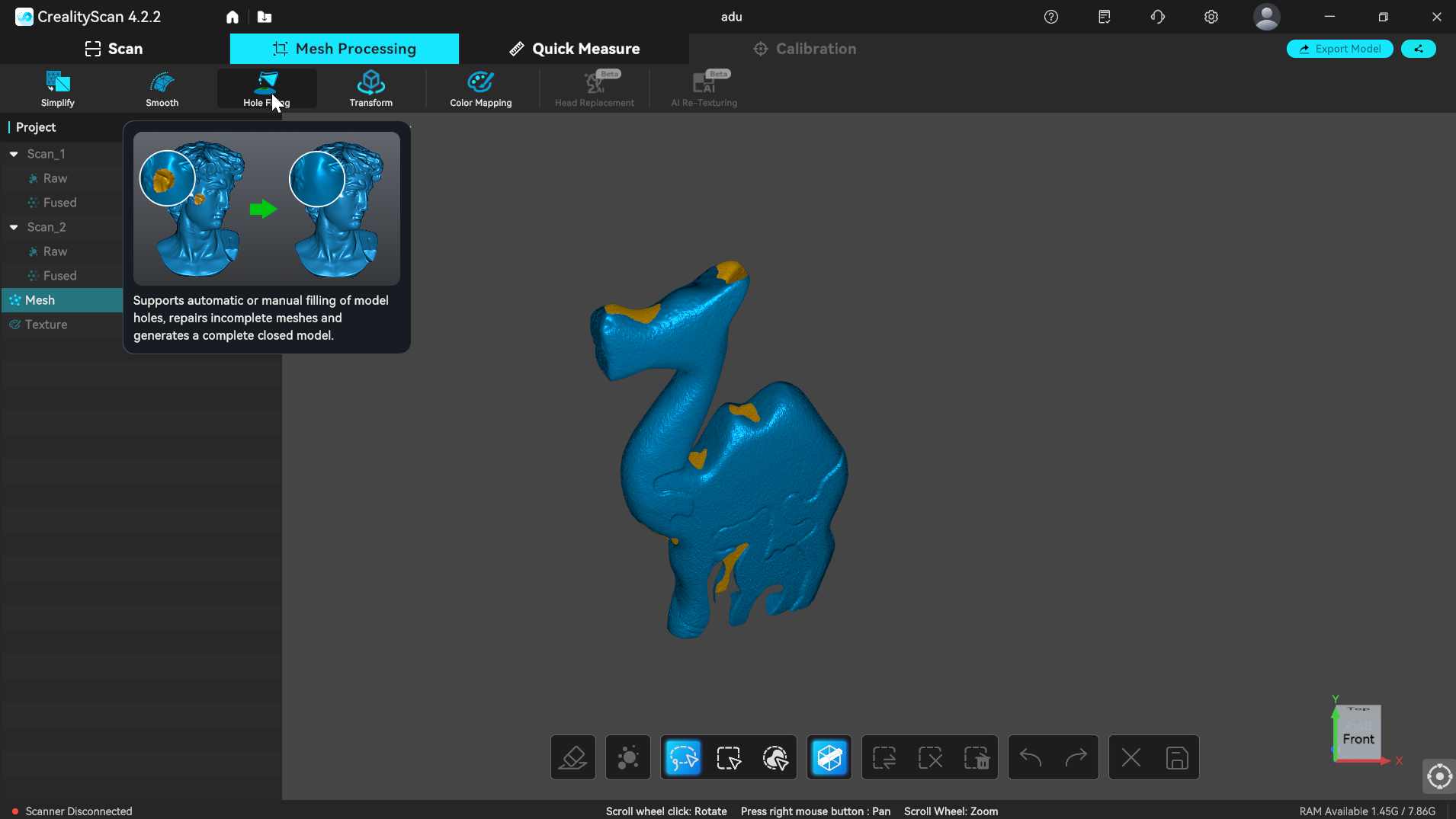
Since my object had holes, free aire spaces(goldsih red regions) and i wanted something solid, I used the holefill under to fill all the holes on my object,
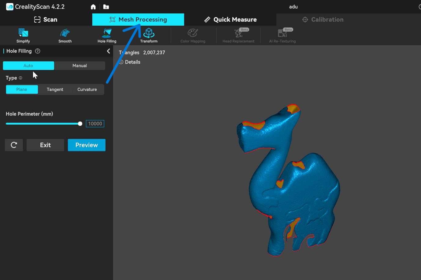
Auto vs Manual - At first, I used auto which deteced the holes automatically and filled them and selected the type as plane which ensures,…and my hole parementer to 10000mm which also enures…, then later on , it could not detect at the bottom and i switched to manual and marked the areas with holes then filled them manually. after settings the type, hole filling mode and hole parameter, you click preview then apply, and it will aplly the changes
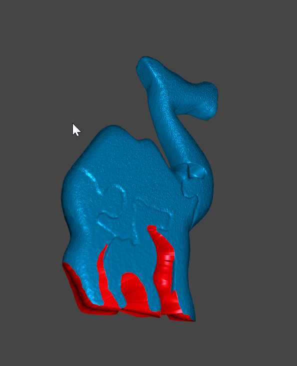
I marked the bottom holes manually and filled them. Now i have complete object with no holes.
Color Mapping
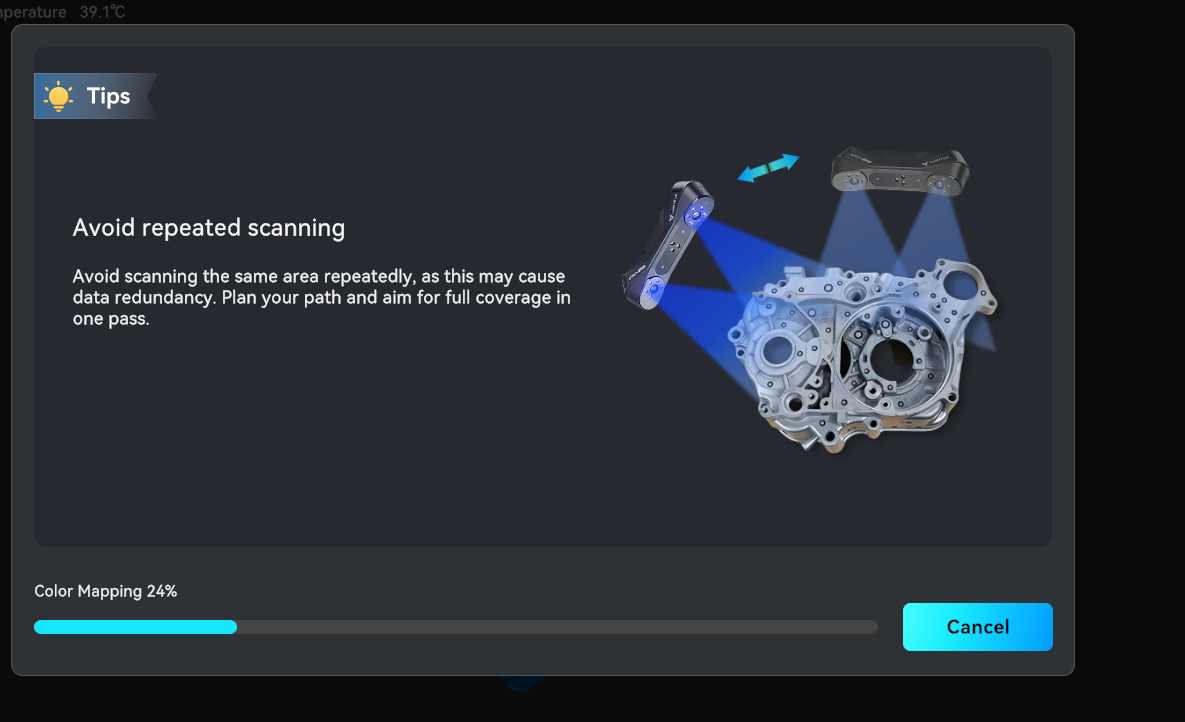
To preserve the appearance of the original object, I performed color mapping. This process projected the captured color information onto the mesh surface.
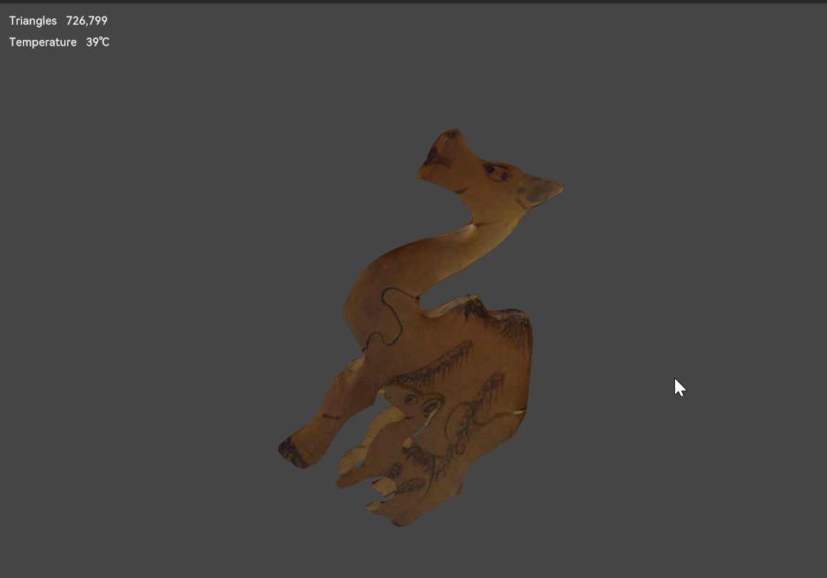
Time to export .obj file
After evrthing is set, you export the obj file, now for printing.
Note: Without proper hole filling, i experienced this error
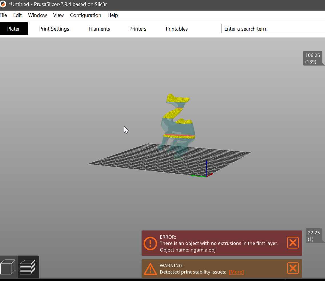
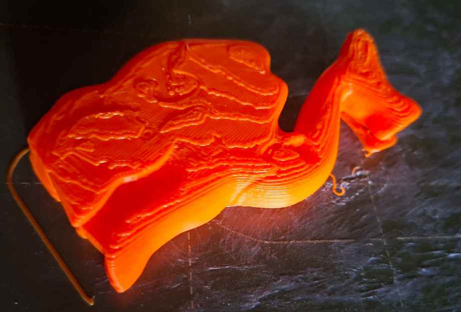
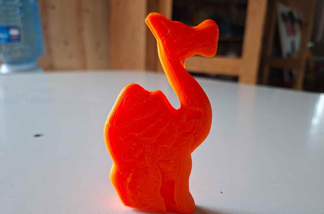
I sliced, and obtained my final product, which I will use as decoration in my room!
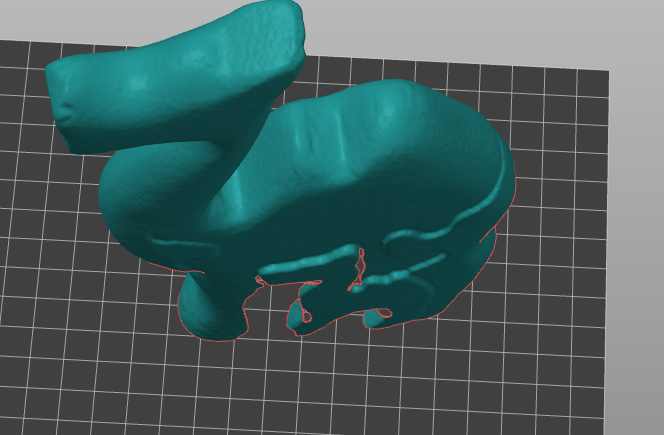
Final Object