3. Computer-Controlled Cutting
This week focused on computer-controlled cutting.
We were introduced to parametric design and laser cutting processes.
Weekly Assignment
Group Assignment
- Complete the lab safety training
- Characterize the laser cutter by testing:
- Focus
- Power
- Speed
- Rate
- Kerf
- Joint clearance
- Different joint types
Individual Assignment
- Cut an object using the vinyl cutter
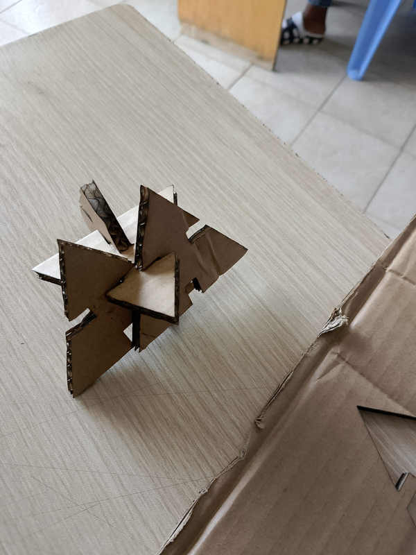
- Design, laser-cut, and document a parametric construction kit, taking into account:
- Laser cutter kerf
Extra Credit
- Design the kit so it can be assembled in multiple configurations
- Include parts that are not flat
- Use engraving in addition to cutting
Group Assignment
What is Parametric Modelling
Parametric modeling is a CAD/CAM process where 3D models are created using adjustable variables (parameters) like length, width, and angle, rather than fixed dimensions. Changing a parameter automatically updates the entire model, allowing for rapid design revisions and automated creation of complex parts, which is crucial for efficient CNC programming, customization, and manufacturing.Parametric modeling also uses constraints to clarify geometric relationships between design features. Benefits of Parametric Modelling: Easy Changes: Edit models easily without redoing the entire design. Design Alternatives: Rapidly test different sizes or configurations. Reduced Complexity: Manage complex, variable-driven components efficiently. Standardization: Maintain design rules and standards
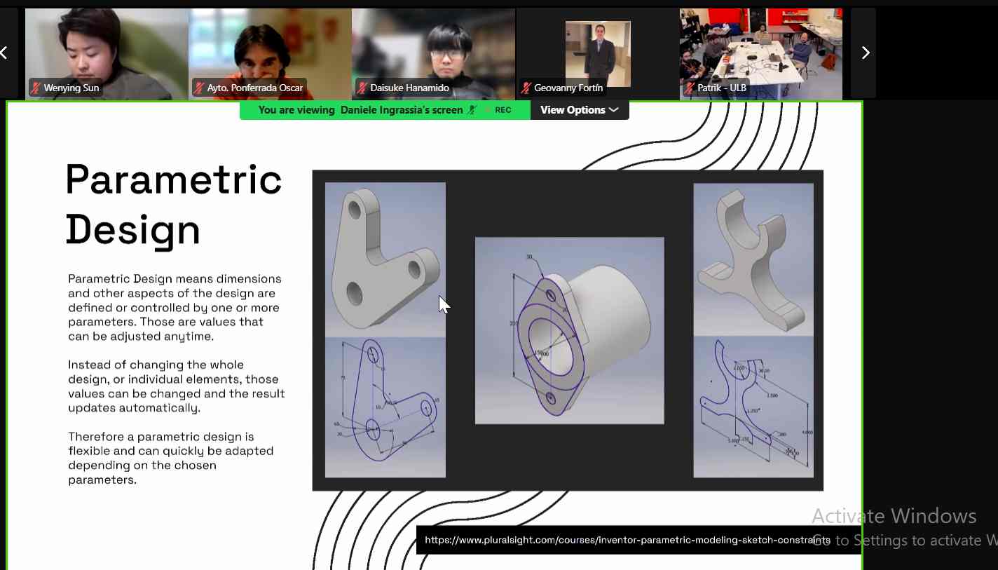
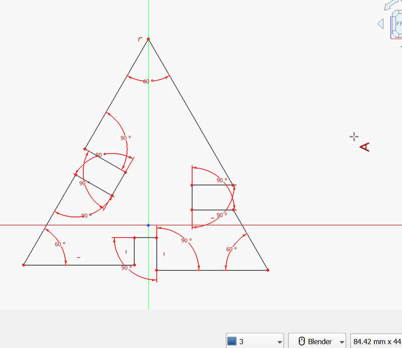
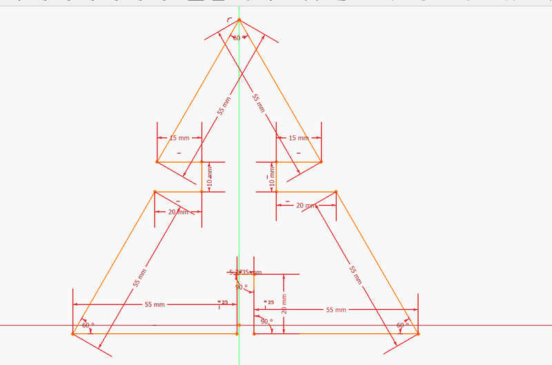
We had a session with our instructor explaining the meaning of parametric design. The explanation was done using simple examples, including a triangular construction kit, to show how dimensions can be controlled using parameters instead of fixed values.

Design Process
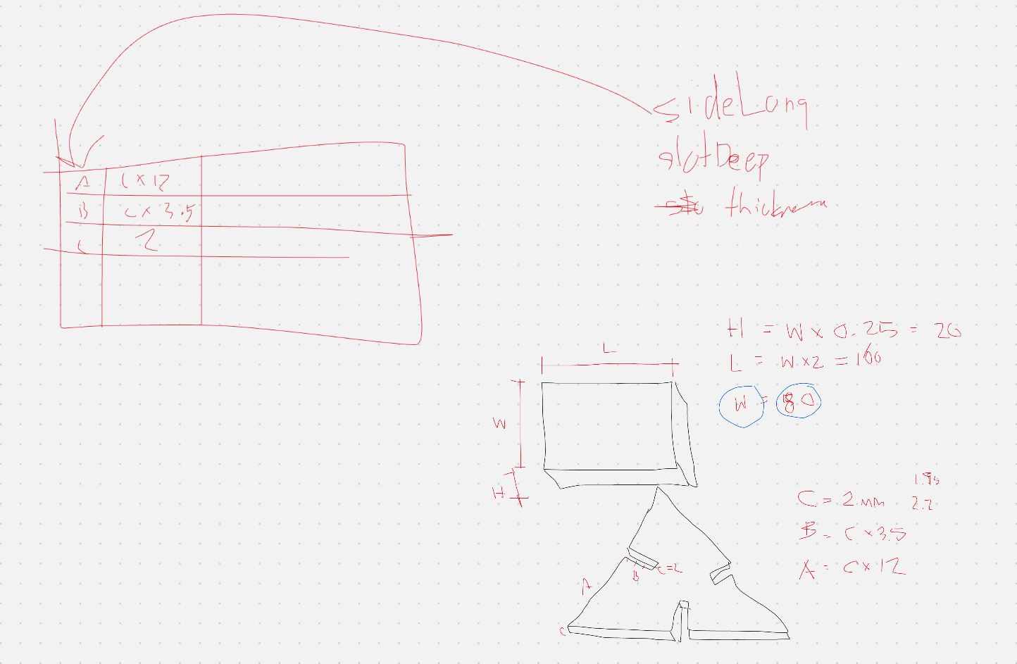
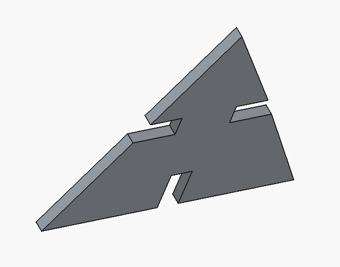
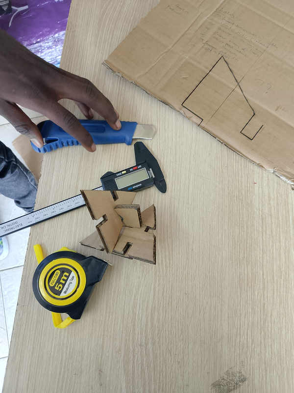
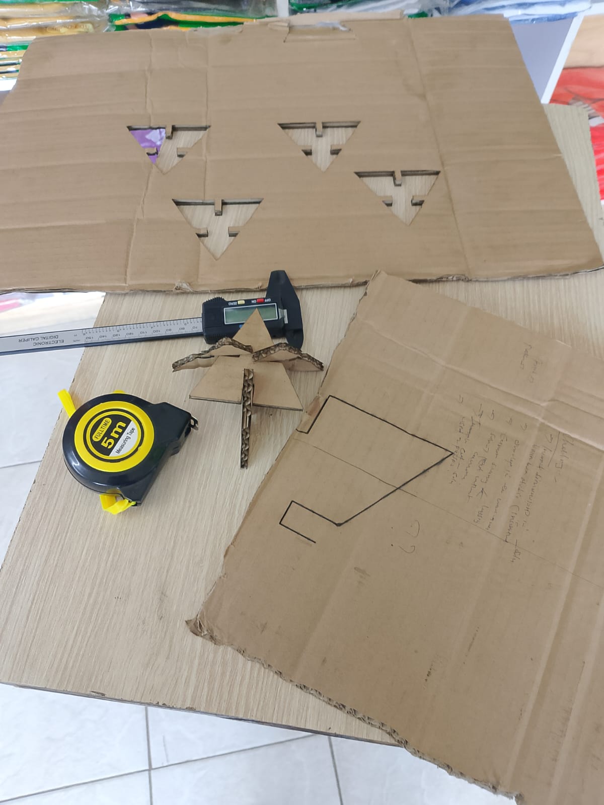
I used FreeCAD to design the triangular kit part. The design was created parametrically using a spreadsheet to control key dimensions. Parameters such as material thickness, height, and kerf were defined as variables.
The slot width was not defined as a fixed value, but as a formula:
Slot Width = Thickness − Kerf
This ensures proper press-fit joints by compensating for material removed during laser cutting. When the kerf or material thickness is modified, the entire design updates automatically.
Parametric Design in FreeCAD
I started by creating a new sketch using the Sketcher workbench in FreeCAD.
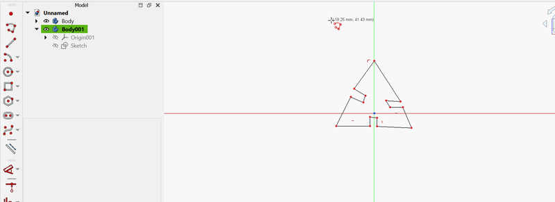
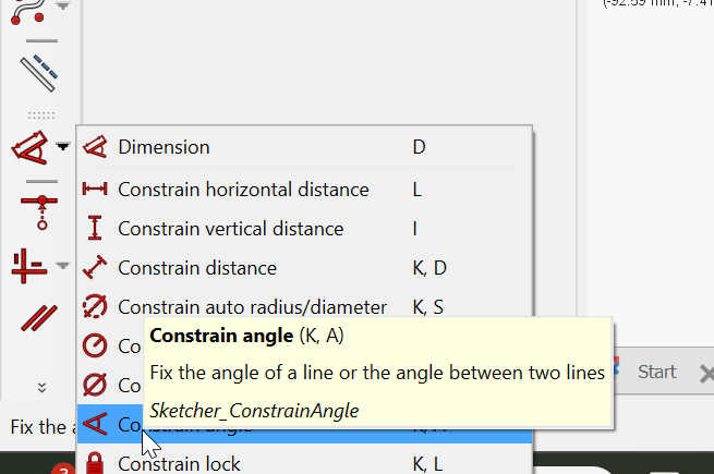
I drew the basic shape using the line tool and applied horizontal and vertical constrains to ensure straight edges. Since the shape was an equilateral triangle, I applied angle constrains of 60° on all sides. While constraining the sketch, I avoided over-constraining it by not adding unnecessary constrains.
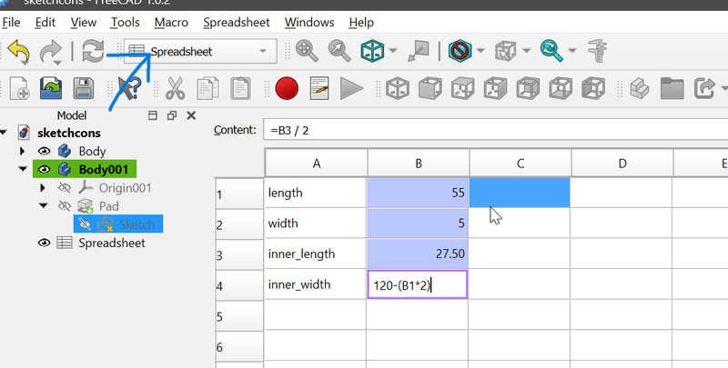
Using Spreadsheet for Parametric Control
To control dimensions parametrically, I created a Spreadsheet in FreeCAD. Key values such as lengths and slot sizes were entered, and formulas were used to maintain relationships between dimensions. Important cells were assigned aliases, which allowed them to be referenced directly in the sketch.
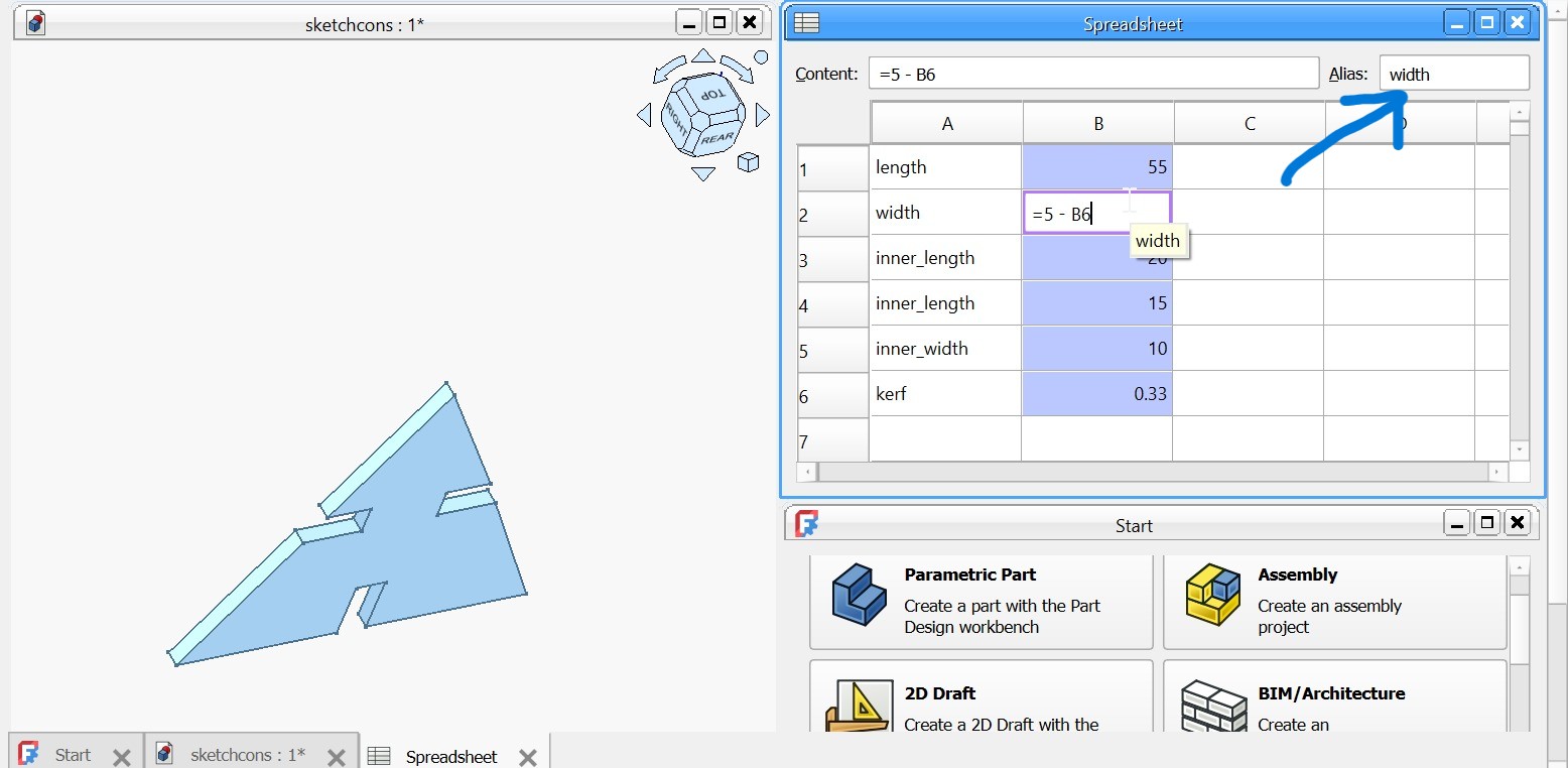
Adding alias
In the spreadsheet, aliases are used to assign meaningful names to parameter cells instead of referring to them by their default cell positions such as A1 or B2. To add an alias in FreeCAD, I selected the desired cell and then used the Alias field in the Property View panel on the top right to assign it a name. I chose alias names that matched the parameter each cell represented, such as width, to keep the design clear and organized. This made it easier to link the parameters to sketch constraints and avoided confusion while working on the parametric model.
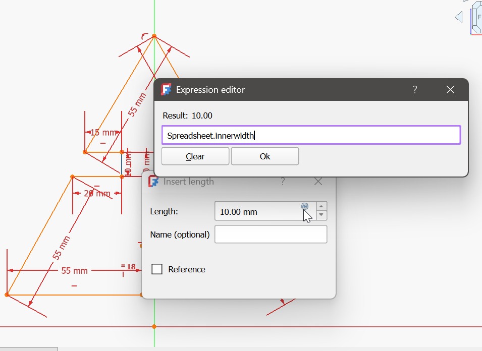
While adding dimensions in the sketch, I applied distance constraints and linked them directly to the spreadsheet aliases instead of entering fixed numerical values. To do this, I first selected applied the distance constraint. Then, in the constraint value field, I clicked the expression (f(x)) icon and began typing Spreadsheet. dont forget the dot. sign after the spreadsheet followed by the alias name. FreeCAD automatically suggested the available aliases, allowing me to select the correct parameter. This approach ensured that all dimensions were controlled parametrically, so any change in the spreadsheet values automatically updated the entire sketch.
At this stage, the triangle was fully constrained.
Sketch Alignment Issue and Fix
I encountered an issue where the hypotenuse edges were not properly aligned.
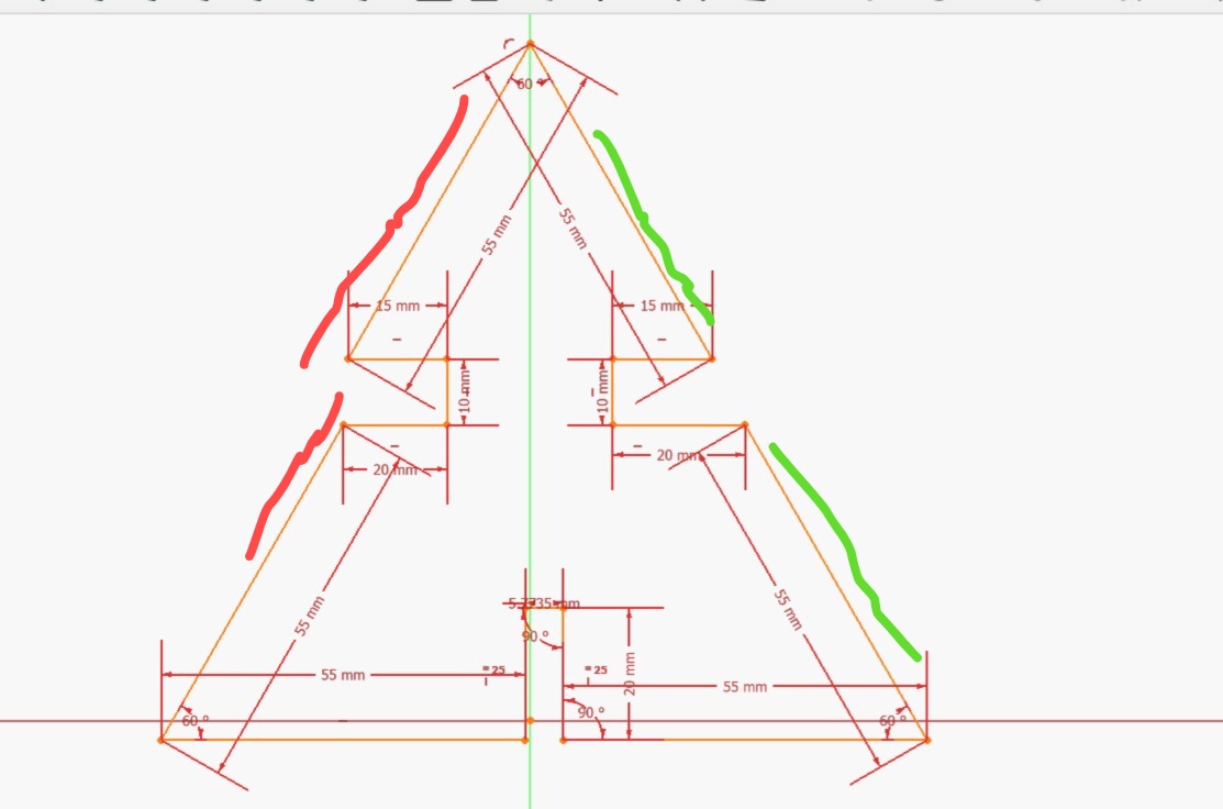
After sharing the issue with my instructor, he advised me to use coincidence constraints and align the hypotenuse edges with the Y-axis. Applying these constraints fixed the alignment issue.
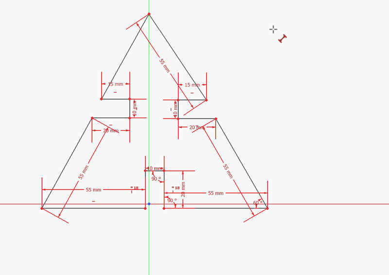
Padding and Part Design
After finishing the sketch, I padded it to create a solid using a padding thickness of 5 mm, which matched the thickness of the cardboard material. I also encountered an issue where the Task panel was missing, which I fixed by enabling it under View → Panels → Task.
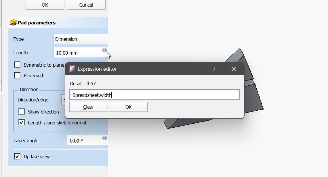
The final pad was applied to turn the sketch into a 3D object. Instead of using a fixed value, I linked the pad length to the width parameter in the spreadsheet using the expression (f(x)) tool, making the model fully parametric.
Fabrication Preparation
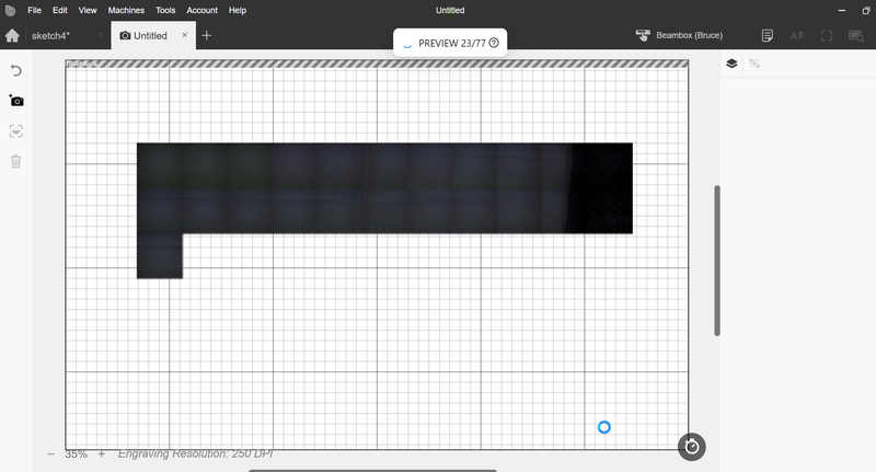
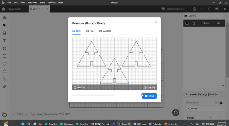
After completing the parametric design, I initially exported the body, which caused extra lines in the laser software. Exporting the sketch instead and saving it as a DXF file solved the problem.
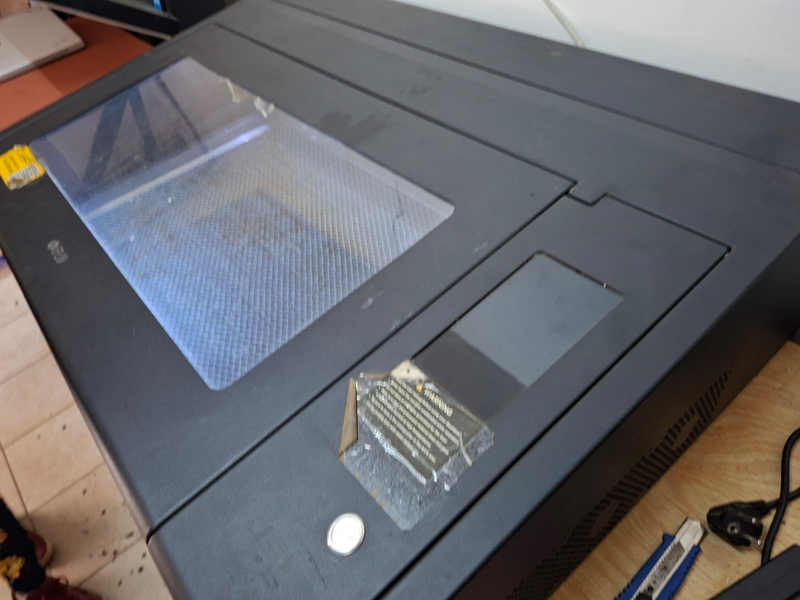
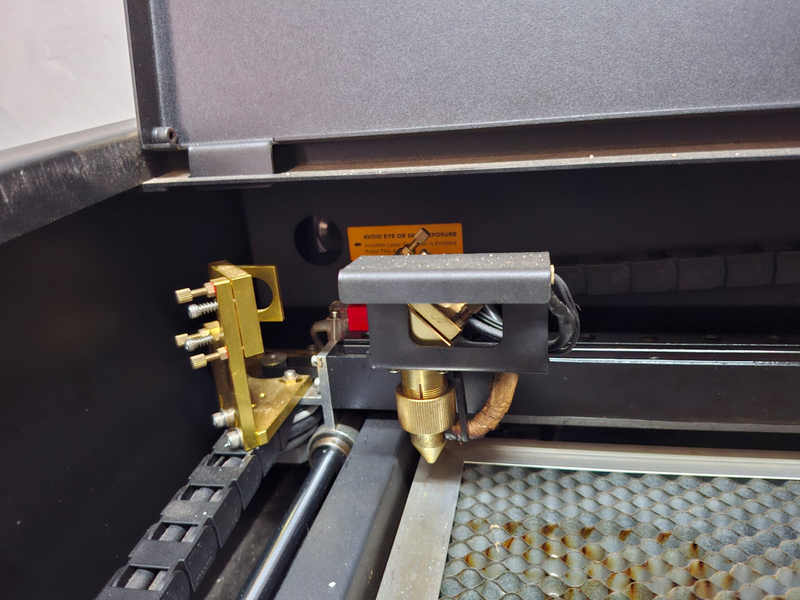
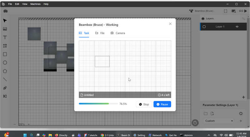
Laser Cutter Setup (FLUX Beambox)
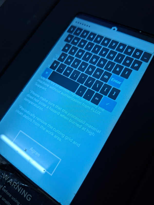
At Fablab Winam, we use the FLUX Beambox laser cutter. Before operating the machine, I followed all safety precautions and documented them as part of the group assignment.
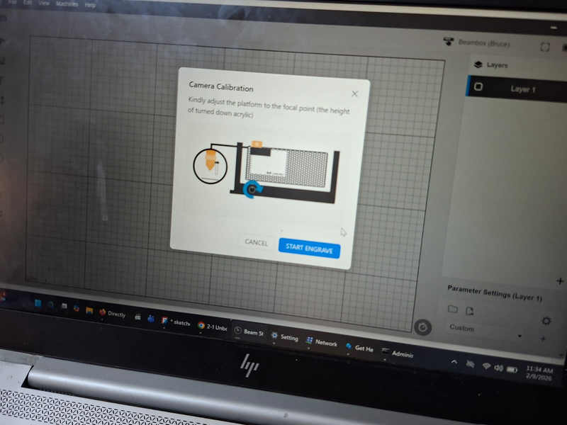
I installed Beam Studio Flux Beambox software and performed the camera calibration.
Connecting the Laser to Beam Studio
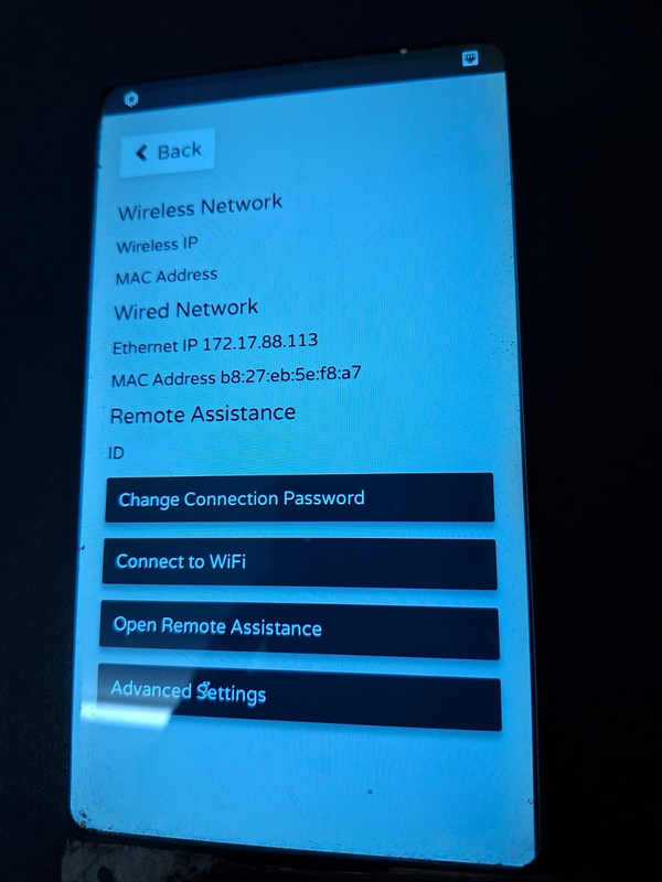
The laser cutter was connected using a wired Ethernet connection. I initially faced network issues, which were resolved by manually assigning an IP address within the same network range as my laptop.
Test Cut
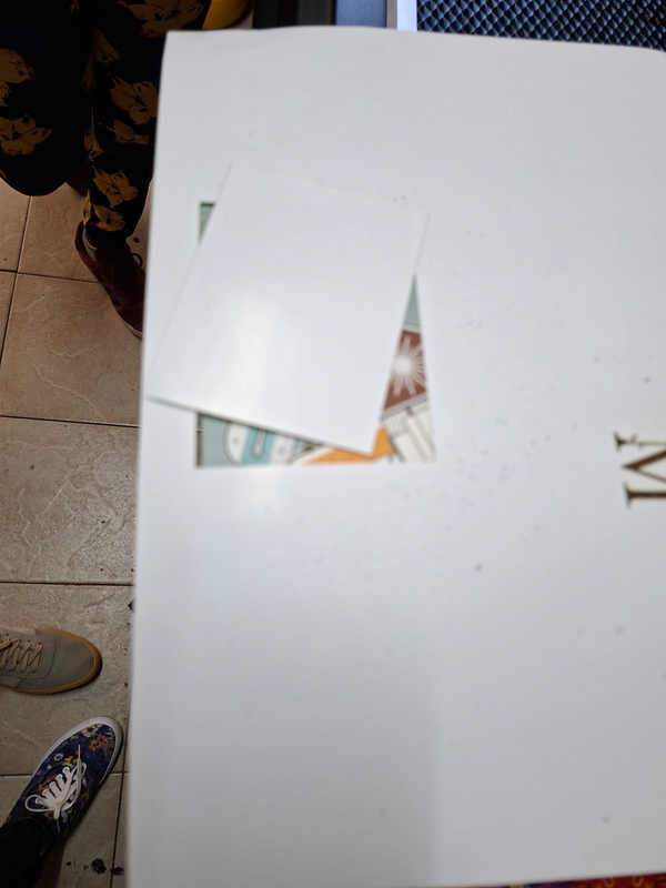
A test cut was performed using paper to confirm calibration, alignment, and basic cutting operation.
The camera view in Beam Studio was used to set the origin accurately.
Cutting the Construction Kit
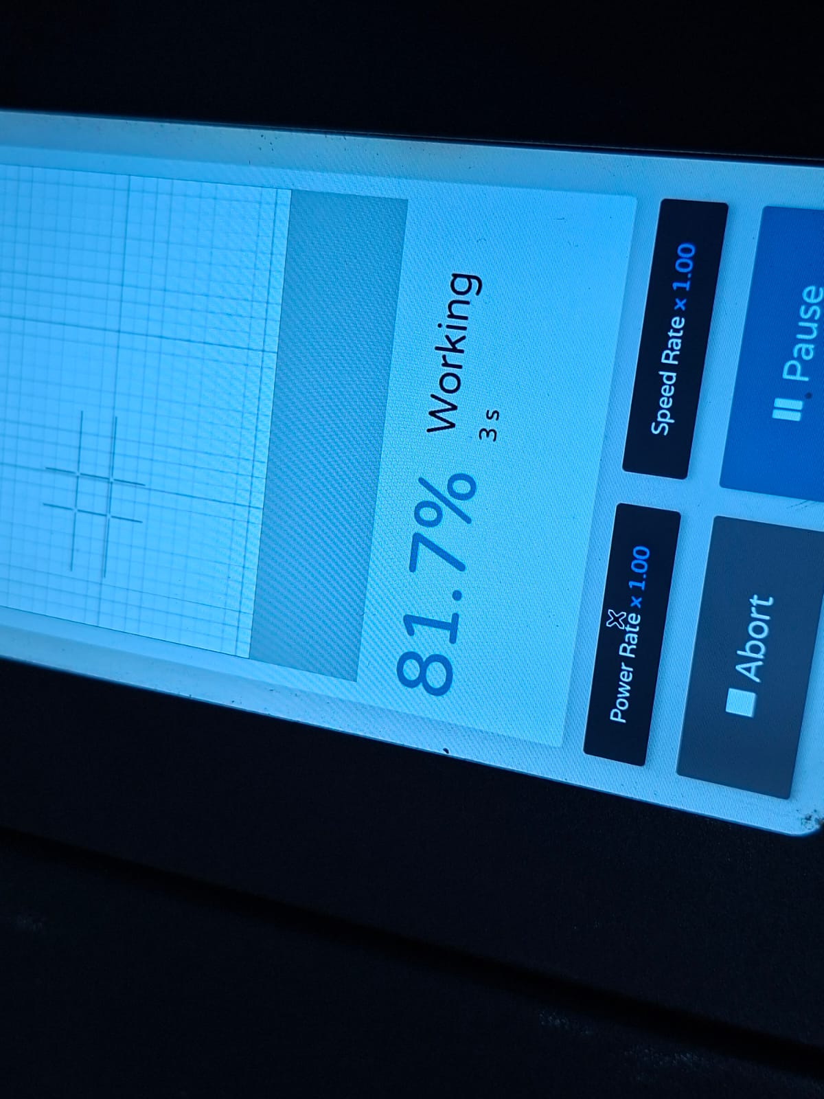
The final kit was cut from 5 mm cardboard using appropriate speed and power settings in Beam Studio.
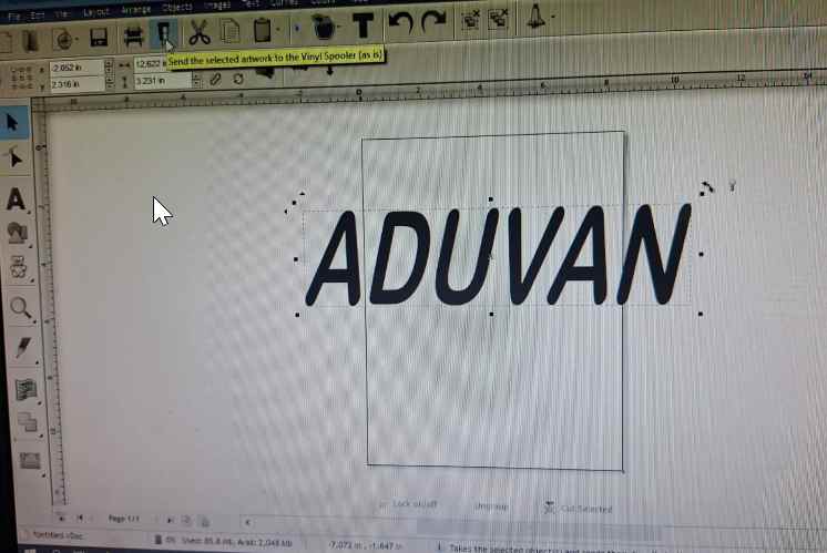
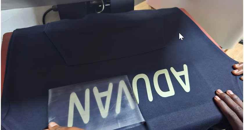
Vinyl Cutting
Designing My vinly week was to design my daughters name,cut and stick it on my hoodie.
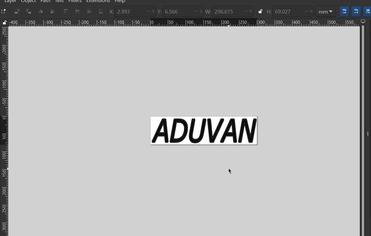
I designed a name using the add text in inksacape. then chosed a font
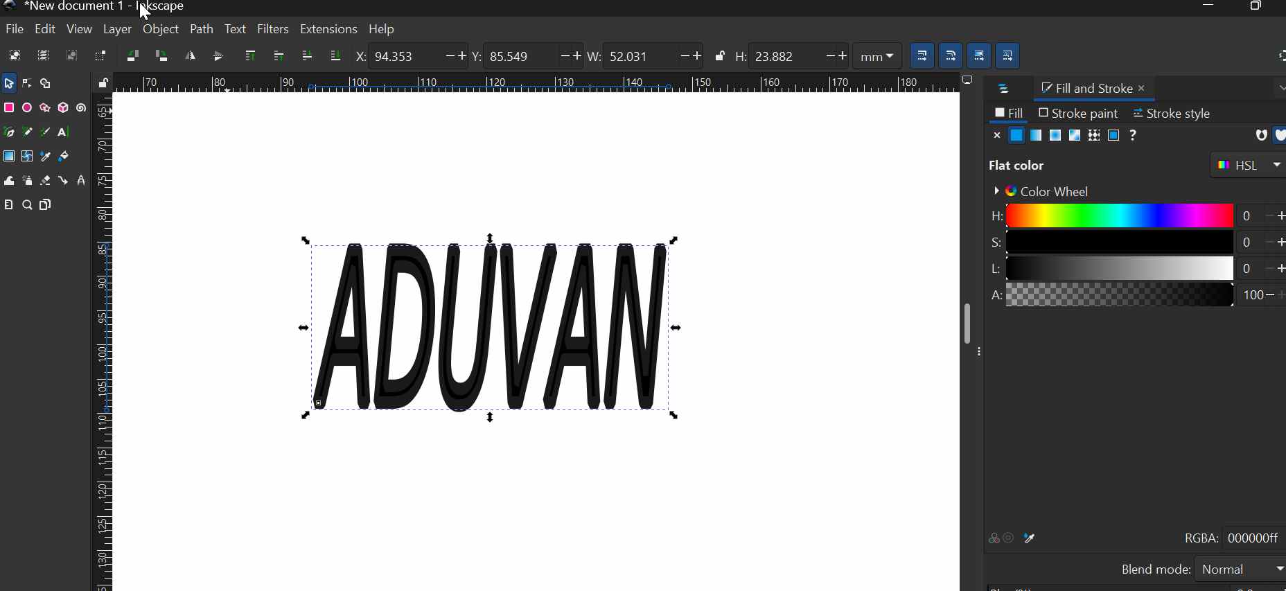
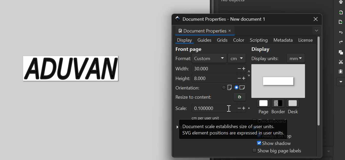
under file, document properties i changed the measurements from pixels to cm and then spcify the size of the text to 30cm width by 8cm height.
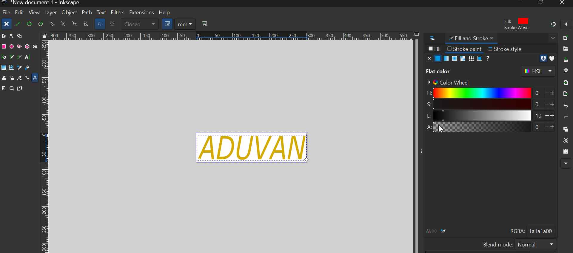
I needed goldish color, i changed the color to HSL which enables…
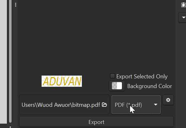
 Then exported as .pdf for cutting in using sign master.
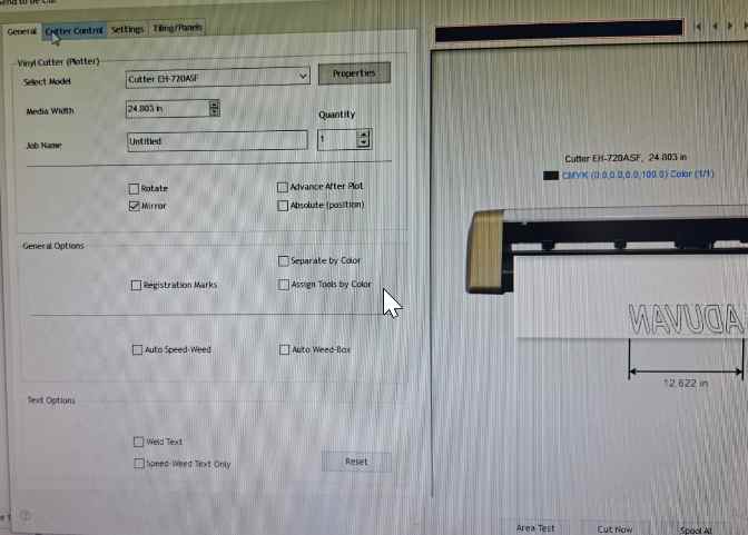
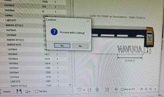
Printing using Signmaster software
My plotter is Model EH-720ASF You connect using the usb cable, then you load the file and click area test to let the ploter calibrate. Then you click cut spindle to…
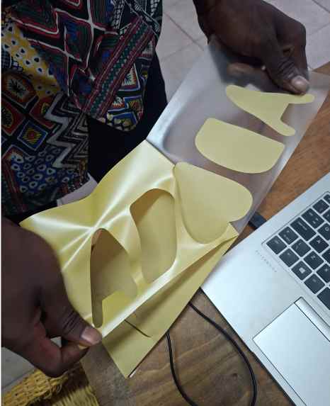
Heat Press
 Key Take Aways
Parametric design = flexible design → change one value, whole model updates Kerf matters → use: slot = thickness − kerf for proper fit Use constraints + spreadsheet → clean, controlled design Export sketch (DXF), not body → avoid cutting errors Laser settings (power, speed, focus) affect cut quality Test before final cut → saves material Safety first when using machines