Appearance
WEEK 16 – System Integration
Individual Assignment
- Design and document the system integration for your final project
1. System Overview
My aim was to integrate the mechanical components, electronics, power supply and control interface of SloshX into a working liquid-dispenser demonstrator.
The electronic system comprised two subsystems communicating through Bluetooth Low Energy (BLE):
| Subsystem | Components and Functions |
|---|---|
| Main Controller | An Arduino UNO R4 WiFi with my custom “flow-rate shield board.” The assembly included a start/stop button, a dimmer switch for manual liquid-flow adjustment and two RGB LEDs: one indicated liquid-flow status through red, green or blue light; the other provided white illumination when the system was on. Additional I/O connectors provided interfaces for the flow-rate sensor, MaixCAM Pro colour-recognition camera and brushless-pump control. |
| Remote Controller | A custom PCB incorporating a XIAO ESP32-C3 module, a start/stop button, three separate status LEDs (red, green, blue) and a 0.96-inch OLED screen displaying liquid-flow status. |
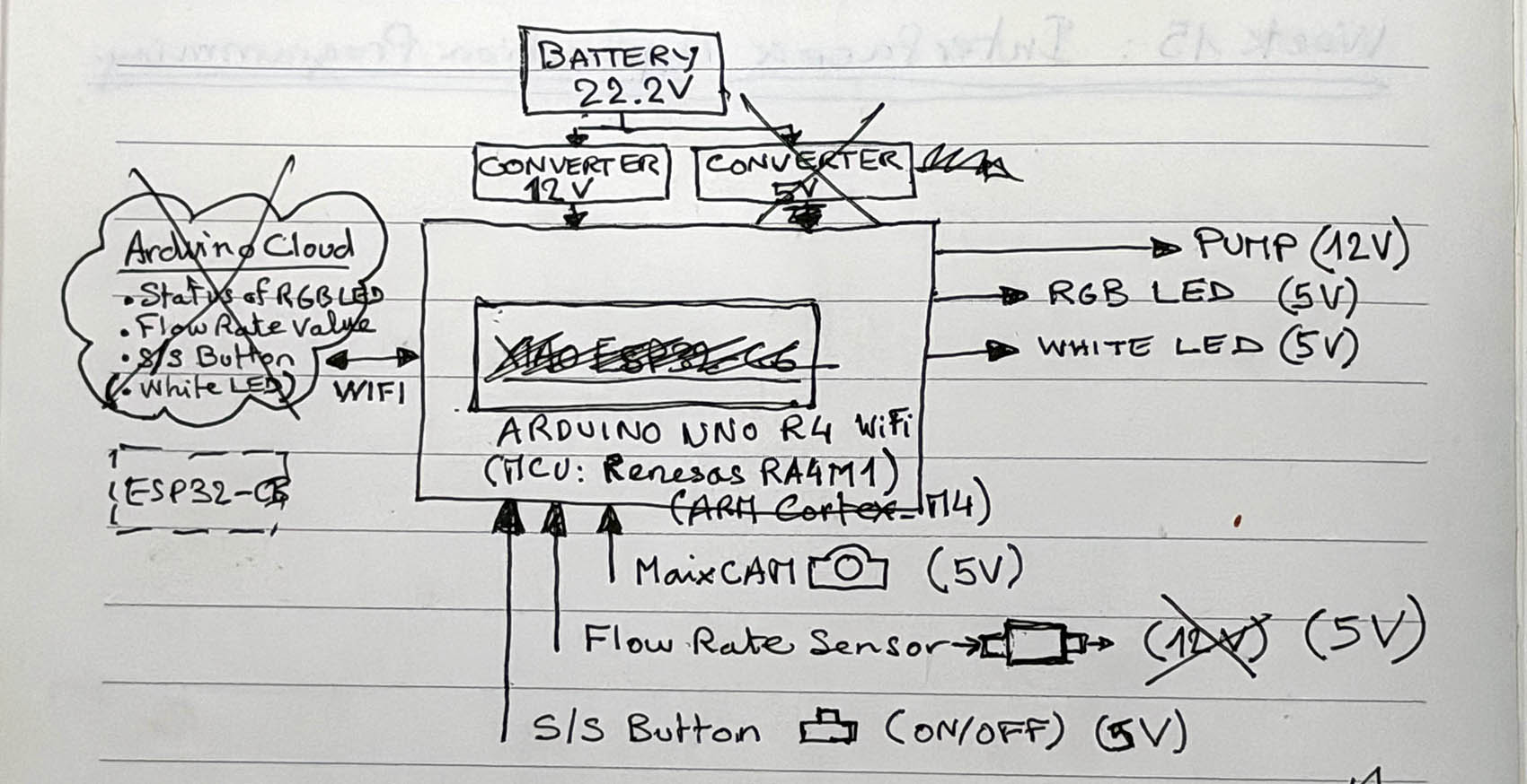 (System diagram showing the main flow-rate controller)
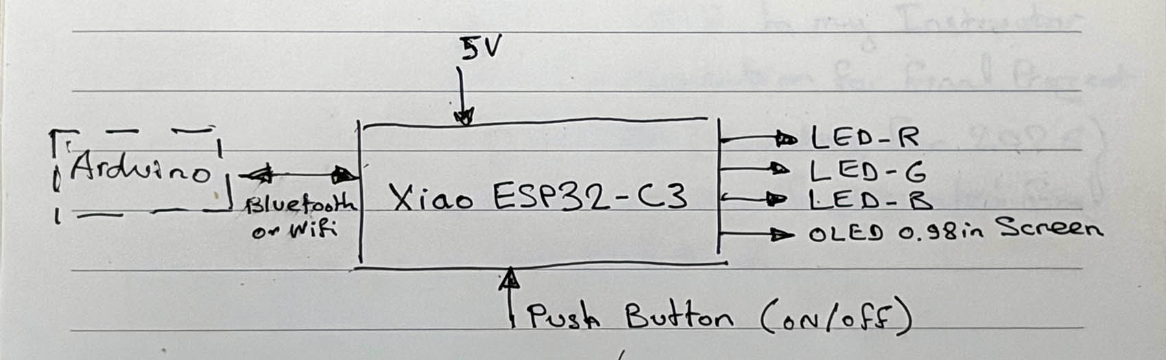 (System diagram showing the remote controller and the Bluetooth or WiFi connection)
2. Integration Approach and Spiral Development
I applied spiral project management: developing initial solutions, testing components and interfaces, identifying problems and refining successive versions before final assembly.
I organised integration into three stages, revisiting earlier stages as needed:
Developed and tested the mechanical structure and component interfaces, providing dedicated locations for the components.
Developed the electronics and dedicated mounts/enclosures, checking the fit between the Arduino, custom board and two-part casing while maintaining access to connections and programming ports.
Connected the subsystems, tested their combined operation and refined the assembly. I added the remote-controller PCB during the final development stage.
Note: Some development work relating to the anti-slosh container cannot be disclosed publicly due to confidentiality requirements. This section therefore focuses on the non-confidential aspects of system integration.
3. Development Schedule
This retrospective Gantt chart summarises development towards my online presentation on 10 June 2026. My SolidWorks folder was created on 9 May and my Electronics folder on 23 May. The development records include PCB files dated 2–3 June and remote-controller code dated 7–9 June. The activity periods are approximate (but precise enough 😃) and reconstructed from dated files, rather than an original planning record.
| ACTIVITY | 9–15 May | 16–22 May | 23–29 May | 30 May–5 June | 6–10 June |
|---|---|---|---|---|---|
| Spiral 1: Mechanical Concepts and Initial Tests | ■ | ■ | |||
| Spiral 2: Mechanical Refinement and Electronics Development | ■ | ■ | |||
| Spiral 3: Main-Controller Enclosure and Control Refinement | ■ | ■ | |||
| Remote-controller PCB and programming | ■ | ■ | |||
| System Assembly and Integrated testing | ■ | ■ | |||
| Presentation Preparation | ■ | ||||
| Online Presentation — 10 June | ◆ |
(Retrospective development schedule. ■ Approximate activity period; ◆ presentation milestone.)
4. Physical Integration and Packaging
► Main Controller
I designed a two-part enclosure for the Arduino and custom flow-rate shield board. I used a CAD assembly of these components to check their relative positions and fit, then refined the enclosure through successive versions.
I secured the Arduino board on the base of the casing using small screws in dedicated places/features and joined the two casing parts using a tight-fit method. The tight-fit method (with the help of a 8mm 3D printed pin in the design under the base of the casing) was also used to secure the whole assembly on the metalic platorm of the drone (which host a corresponding hole).
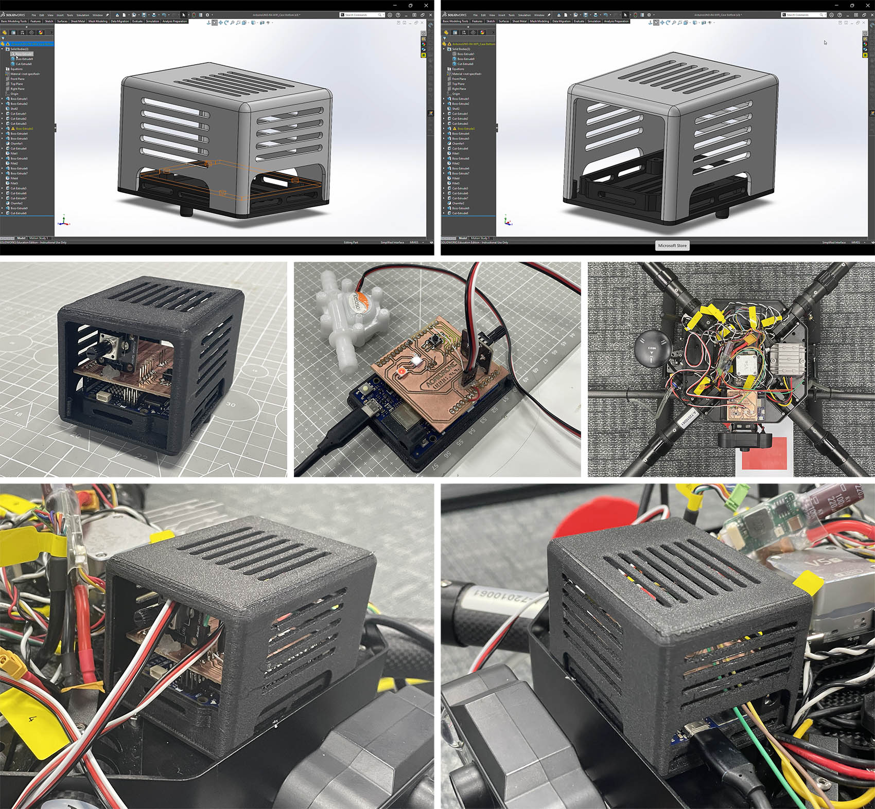 (CAD assembly used to check the arrangement and fit of the main controller and its two-part enclosure + Open and closed enclosure showing the installed boards, mounting and wiring during test and on the drone)
Openings maintained access to the ports, controls and connections. I connected the external components and routed/restrained the cables using plastic tighteners.
► Remote Controller
I designed and fabricated a separate remote-controller PCB incorporating the XIAO ESP32-C3 module, start/stop button, three status LEDs and OLED display. This late-stage addition provided a remote user interface and incorporated a custom embedded-controller PCB into the final project.
The remote controller communicated with the Arduino UNO R4 WiFi main controller using BLE. It was powered through an external power connection (USB cable connected to my laptop).
(Video of the operating remote-controller PCB)
The remote did not have an enclosure at the presentation stage. Its physical packaging therefore remained unfinished and represented a limitation of the demonstrator.
► MaixCam Pro Vision Sensor
A dedicated attachement support was designed and 3D printed for the installation of the MaixCam Pro camera on one leg of the drone.
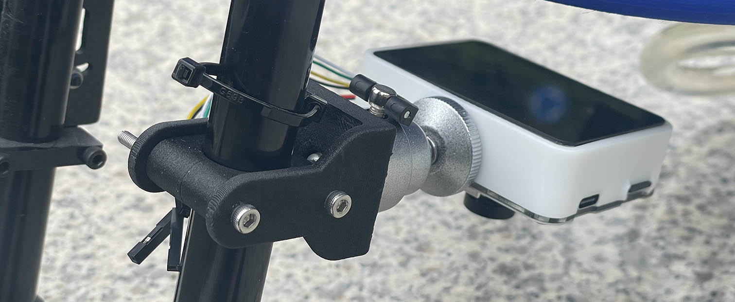 (Picture showing the custom design support to attach the MaixCam Pro camera on the drone's leg)
► A Few Interations + Drone Cover
A few iterations were made on several components during the "spiral" development of my final project. As illustrated below with the drone cover, "test fit" with reduced component shape have been made to optimise development time and material consumption.
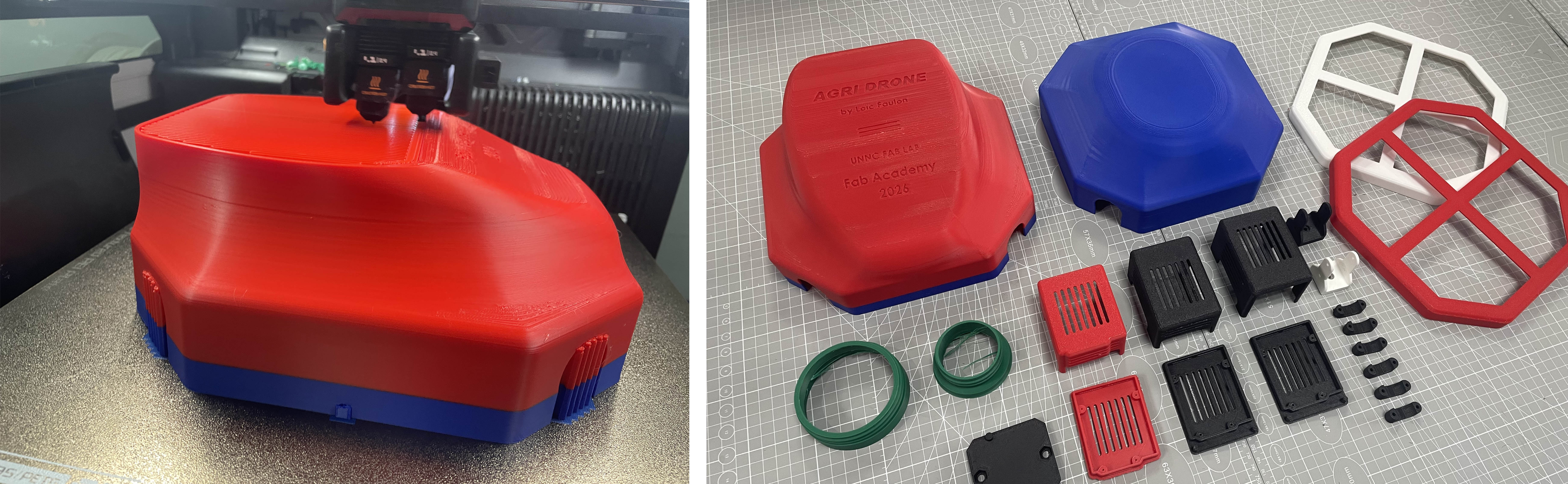 (Picture showing the multiple iterations made on a few parts, including for the drone cover and "test fit" samples.)
5. Integrated testing and outcome
After assembly, I checked the interaction between the main controller, remote controller and liquid-dispensing system.
| Integration Check | Observed Result |
|---|---|
| Local Start/Stop Button and Manual Flow Adjustment | Perfect 😉 |
| Remote Start/Stop Command and BLE Communication | Perfect 😃 |
| Main-Controller Status LED, Remote LEDs and OLED Display | Perfect 😃 |
| Flow-Rate Sensor, Camera Input and Pump Response | One issue encoutered and solved / Confidential Matter / Perfect Now 😃 |
One integration issue was encountered. I addressed it by observing and reflecting on what might be going wrong...The issue was subtle but obvious in some way, I fixed it and repeated the test. The observed result was responding as expected.
I presented the demonstrator online on 10 June 2026 (with a poster and a video). The remaining limitations included the unenclosed remote-controller PCB and the low quality of the short video of my final project which I have fixed since.
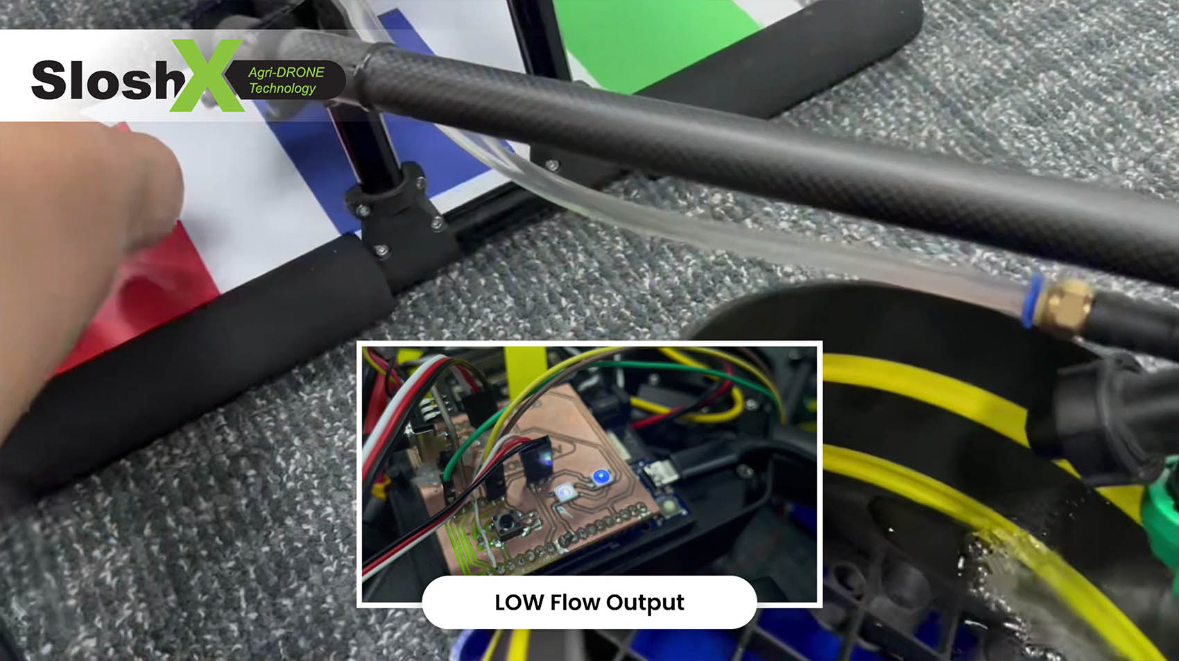 (Screenshot of the system in action - Low Flow Output)
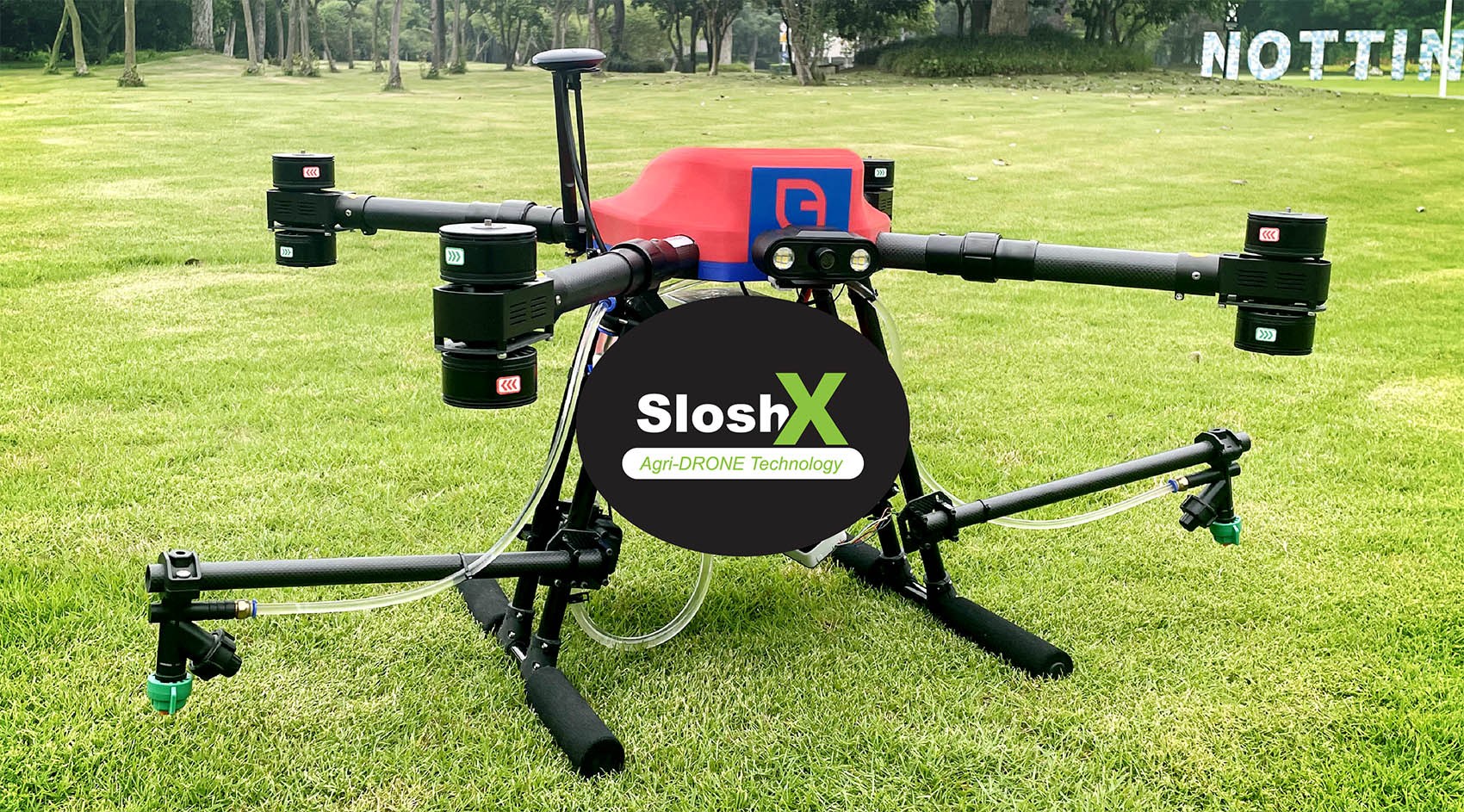 (Picture of the drone with the whole system installed and in working order - SloshX logo to hide the confidential part)
REFERENCE FILES
CAD Files
- CAD_ArduinoUNO-R4-WIFI_Casing(v3)(SW).SLDPRT
- CAD_ArduinoUNO-R4-WIFI_Casing(v3)(STEP).STEP
- CAD_CameraClamp(v1)(SW).SLDPRT
- CAD_CameraClamp(v1)(STEP).STEP
- CAD_CameraSupport(v1)(SW).SLDPRT
- CAD_CameraSupport(v1)(STEP).STEP
- CAD_DroneCover_CptC_(v1)Design1(SW).SLDPRT
- CAD_DroneCover_CptC_(v1)Design1(STEP).STEP
ECAD Files
- ECAD_PCB_MainController(v2)(SW).SLDPRT
- ECAD_PCB_MainController(v2)(STL).STL
- ECAD_RemoteControl(STEP).STEP
- ECAD_RemoteControl(STL).STL