Appearance
WEEK 3 – Computer-Controlled Cutting
Assignments
Group Assignment
- Do your lab's safety training
- Characterize your laser cutter's focus, power, speed, rate, kerf, joint clearance and types
Individual Assignment
- Cut something on the vinyl cutter
- Design, laser-cut, and document a parametric construction kit, accounting for the laser-cutter kerf
- Extra credit: design it to be assembled in multiple ways
- Extra credit: include elements that aren't flat
- Extra credit: engrave as well as cut
Group Work
Our group work is accessible HERE (add the link)
Individual Work
Parametric Design in SolidWorks
Concept: "Flower Shape" Kit
The kit is a family of flat "flower" discs with 2 to 10 radial slots, plus straight sticks of three lengths and a connector piece. The slots let the flowers slot into each other at angles, and the sticks link flowers through their centre slots, so the same parts can build flat, linear and 3D structures.
1. Base Module and Driving Dimensions
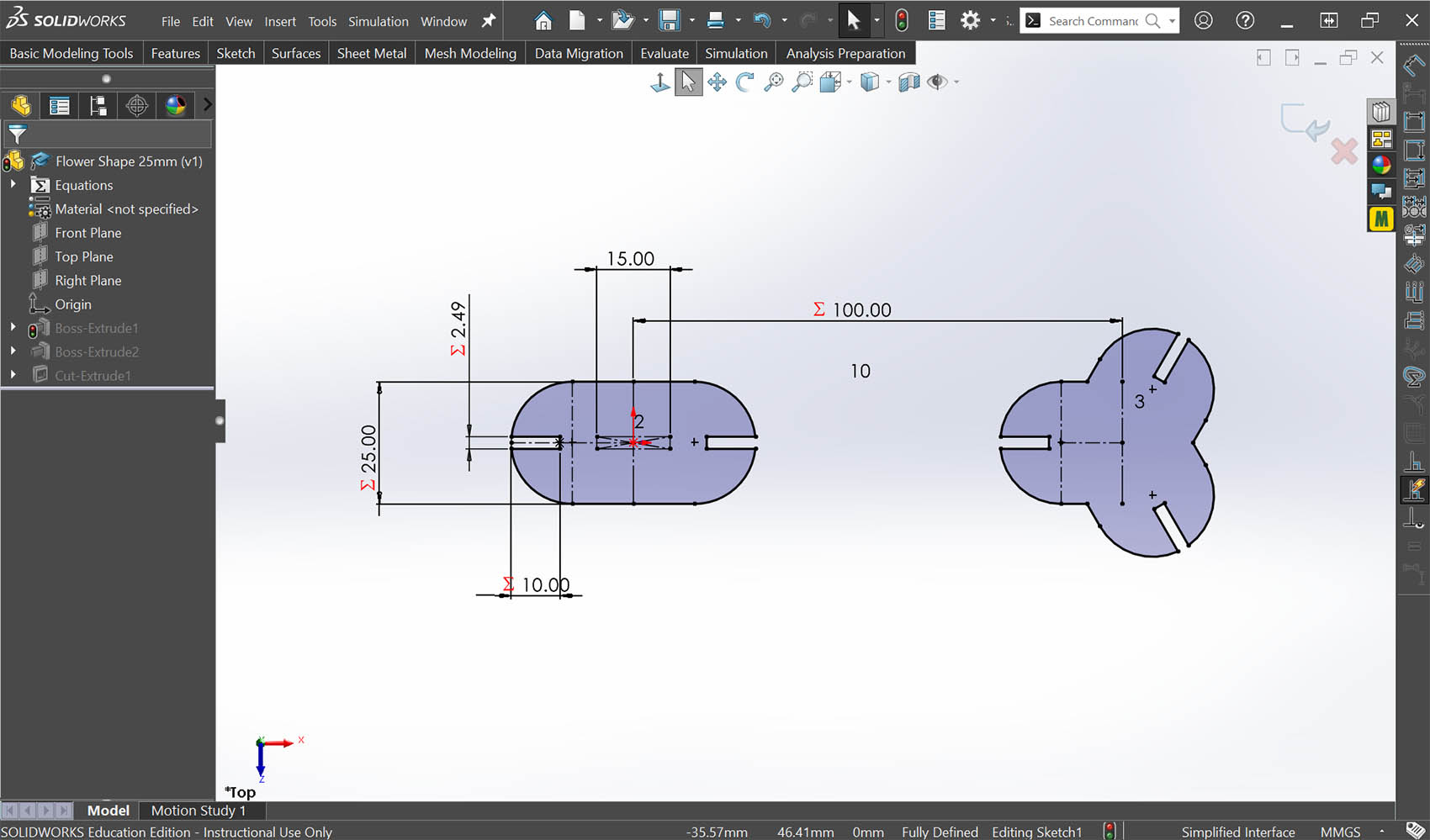
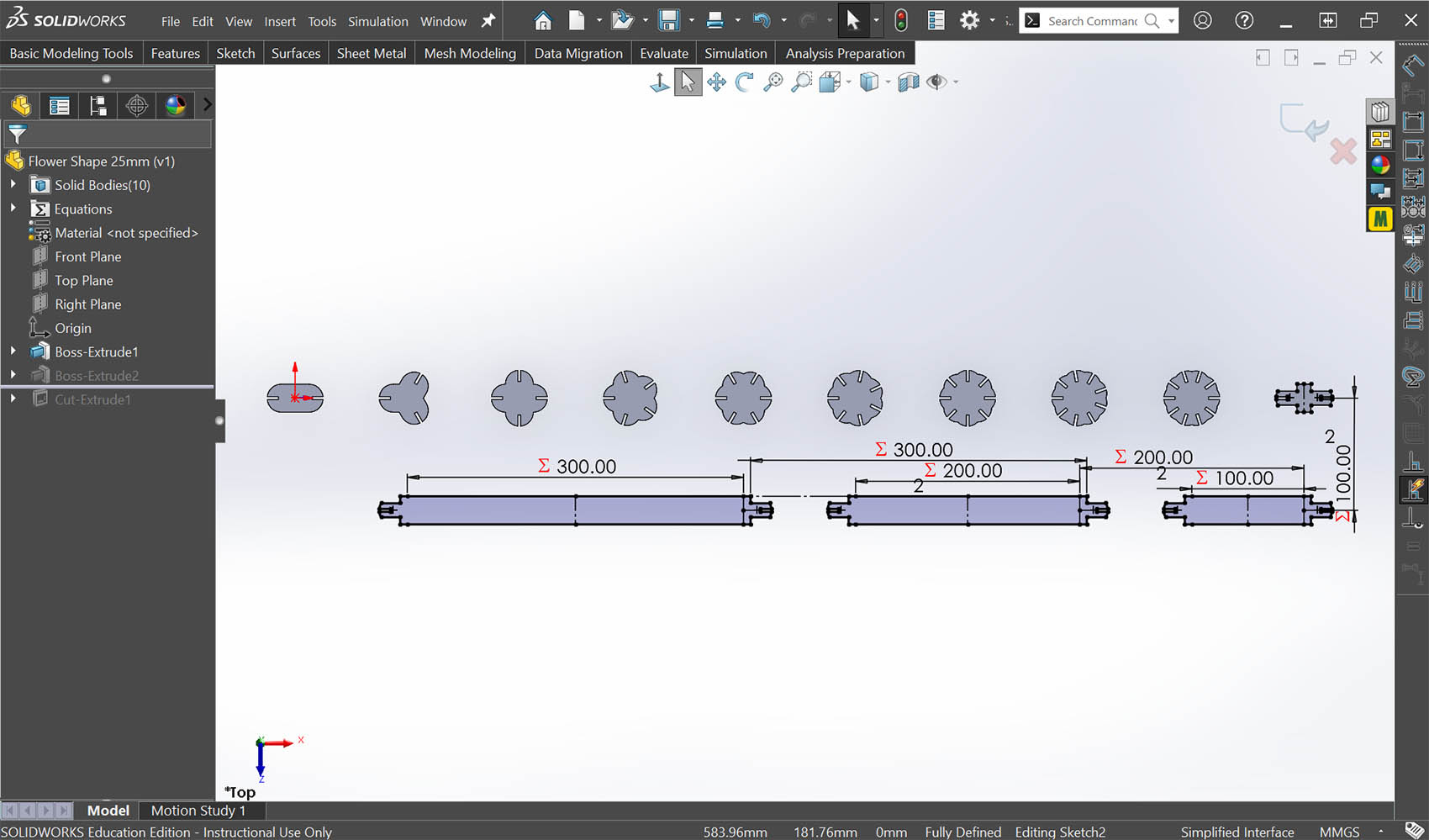
I started from a single base sketch (the 2-slot module) and built the rest of the kit from it. Instead of typing fixed numbers, I linked the key dimensions to global variables so the whole kit could be adjusted later. Dimensions shown with a Σ symbol in the sketch are driven by an equation: slot width (2.49 mm), slot depth (10 mm), inner length (25 mm) and the 100 mm spacing between modules.
2. Equations Table and Kerf Compensation
I set up the parameters in SolidWorks under Tools > Equations as described in the image below which shows the Equations, Global Variables and Dimensions. Thes Slot width is calculated from material thickness and kerf.
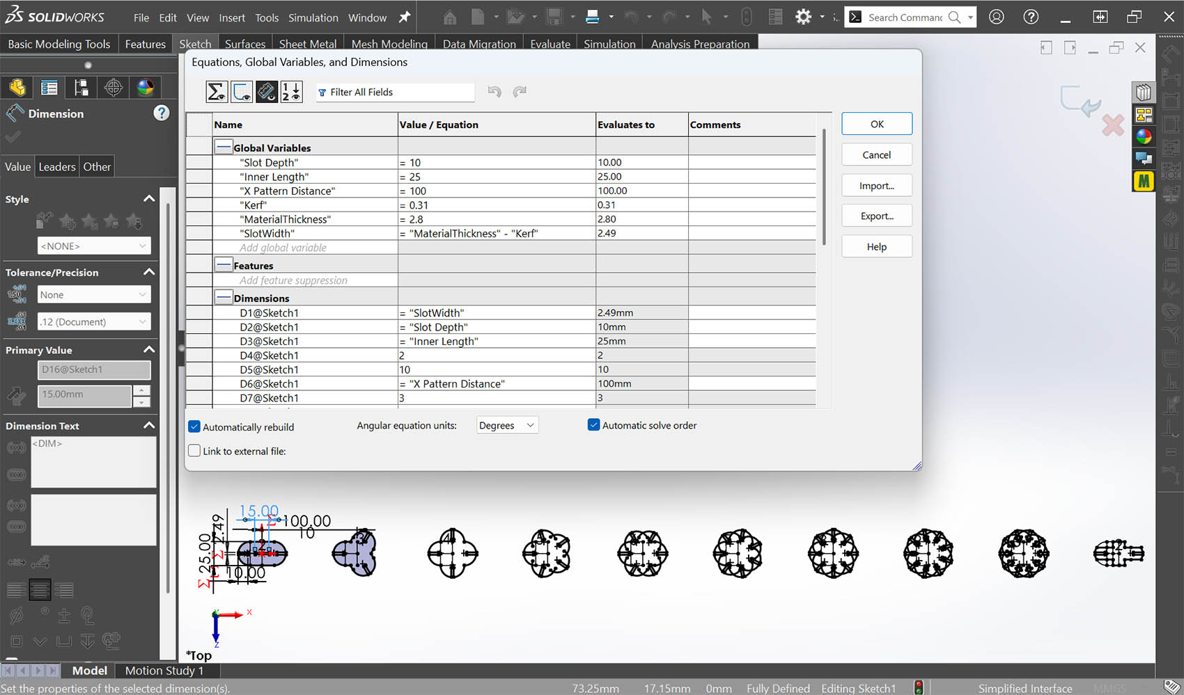
Kerf logic: the laser beam removes a thin strip of material, so every cut slot comes out about one kerf wider than drawn. To get a press fit, I drew each slot narrower by the kerf: 2.8 − 0.31 = 2.49 mm. After cutting, the slot should be close to the 2.8 mm sheet thickness. Kerf is a separate variable, so if I change material or machine I only need to update two values (MaterialThickness and Kerf) and every slot updates.
I linked the sketch dimensions to these variables in the Dimensions section of the same table (for example, D1@Sketch1 = "SlotWidth", D2@Sketch1 = "Slot Depth").
3. Building the Flower Series
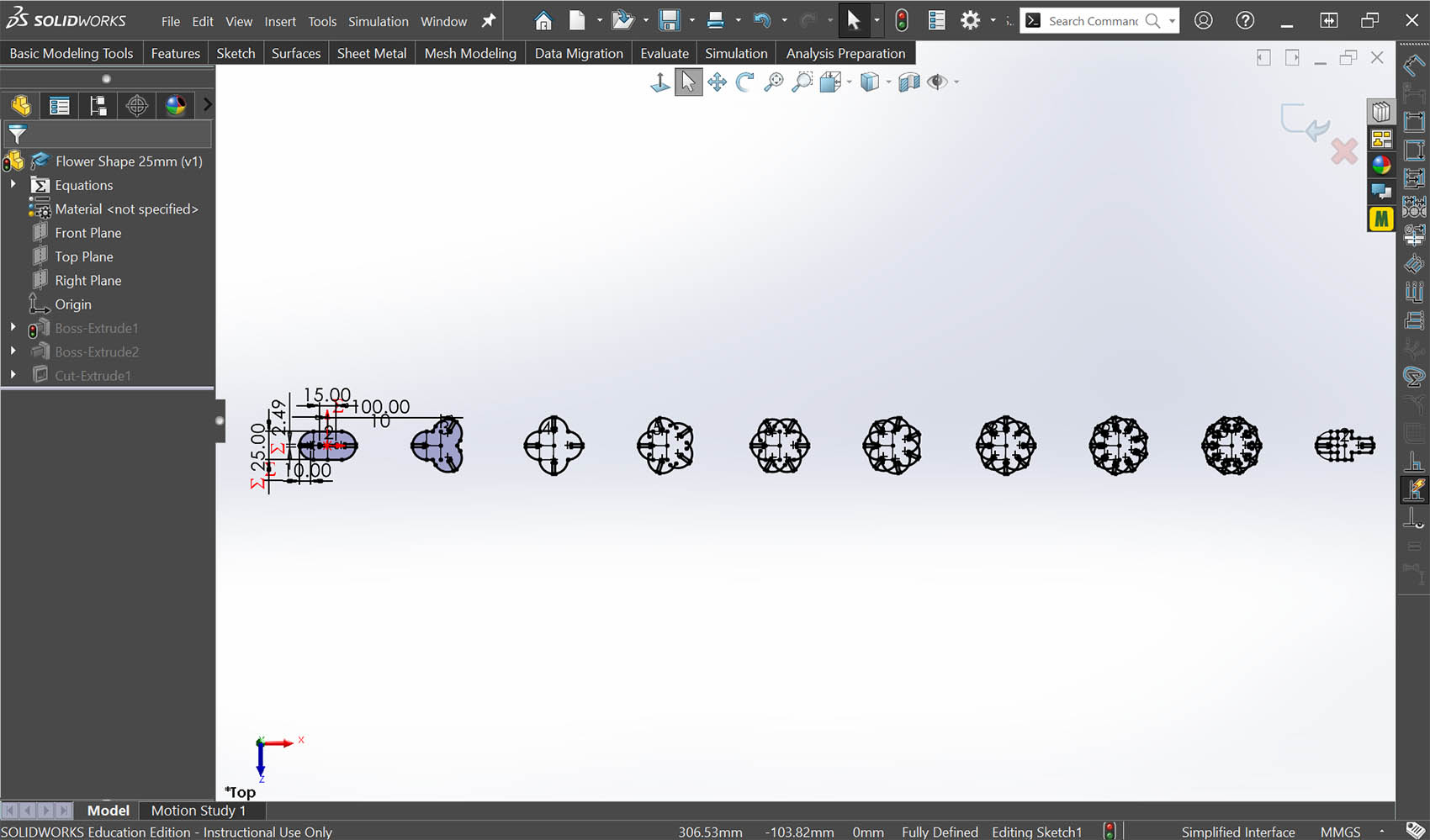
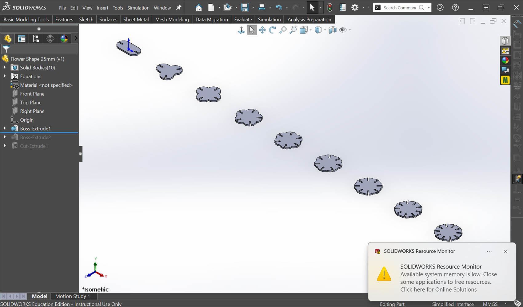
From the base module I built a series of flowers with an increasing number of radial slots, from 2 up to 10. Every slot uses the same parametric slot width and depth, so all flowers are compatible with each other. The parts are spaced using X Pattern Distance (100 mm). I also added a small connector piece. I extruded the sketch to the material thickness, which gave 10 solid bodies in one part file.
4. Adding the Sticks
To make 3D and linear structures possible, I added a second sketch with three sticks of 300 mm, 200 mm and 100 mm, each with a tab at both ends. The tabs can slot into the center slot of the flowers and the peripheral connector slots.
5. Centre Slots and the Complete Kit
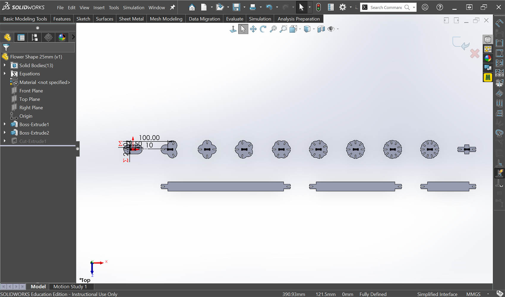
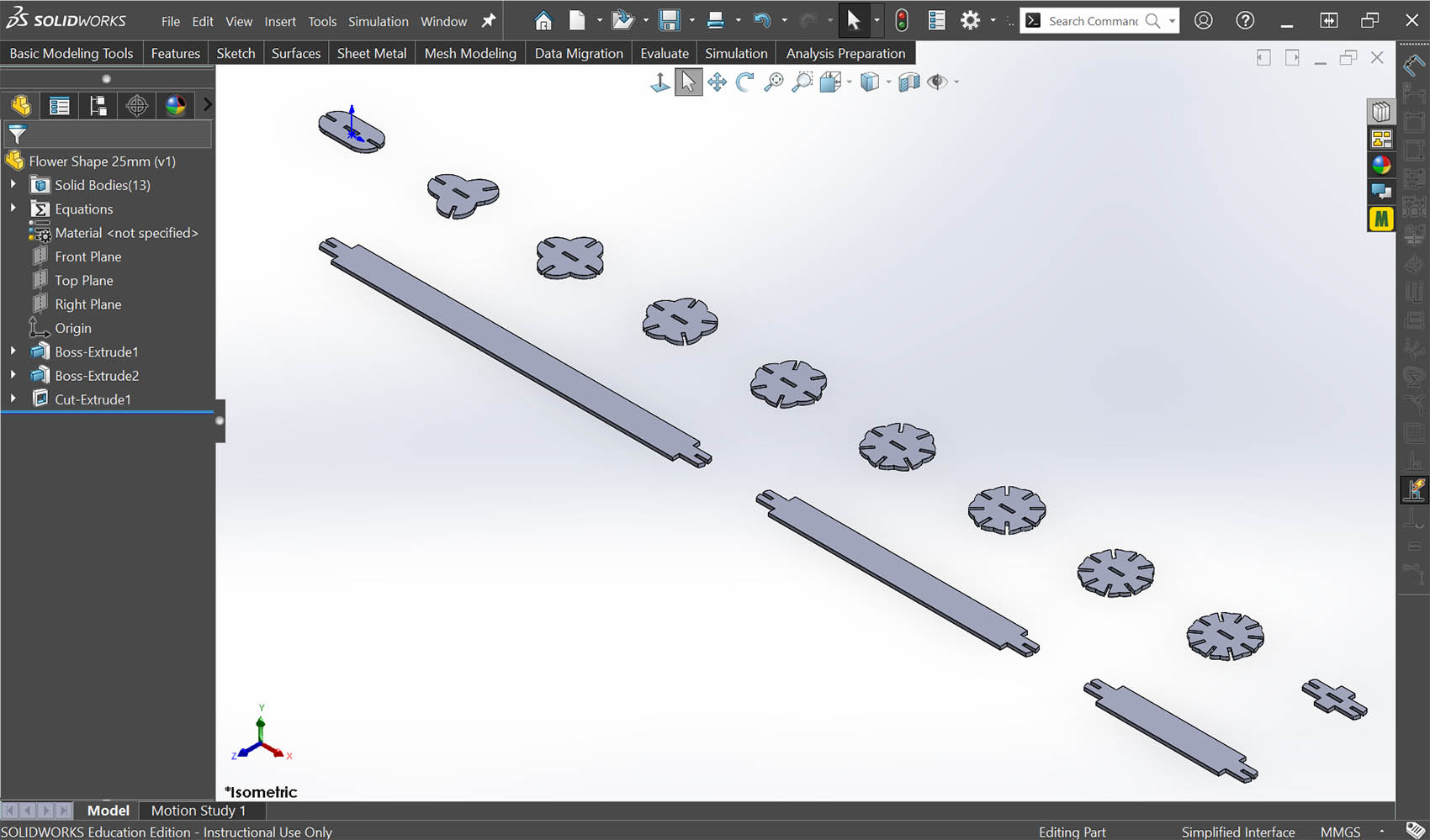
Finally, I cut a centre slot through each flower (Cut-Extrude1) so the sticks can connect to them. The complete basic kit has 13 solid bodies, which I exported for laser cutting (see later below).
6. What is Parametric and What is Not
Most of the joint geometry is parametric: slot width (including kerf), slot depth, module size and spacing are all driven by global variables. Some values are still typed-in numbers, for example the 15 mm centre-slot length, the number of slots on each flower and the stick tab dimensions. If I changed material, these would have to be checked by hand. A next step would be to turn them into global variables too so my paremetric design kit becomes fully-scalable with minimum manual input adjustment.
7. Kit Extension to Bigger Sizes
To test whether the model really was parametric, I made two larger versions of the kit by changing one global variable. In the Equations table I changed "Inner Length" from its original 25 mm to 30 mm, and then to 40 mm. With "Automatically rebuild" switched on, SolidWorks updated the base module straight away, and because every other part is built from that module, all the flowers, sticks and the connector updated with it. I saved each version as a separate part file (Flower Shape 25mm, 30mm and 40mm) so that all three sizes stay available.
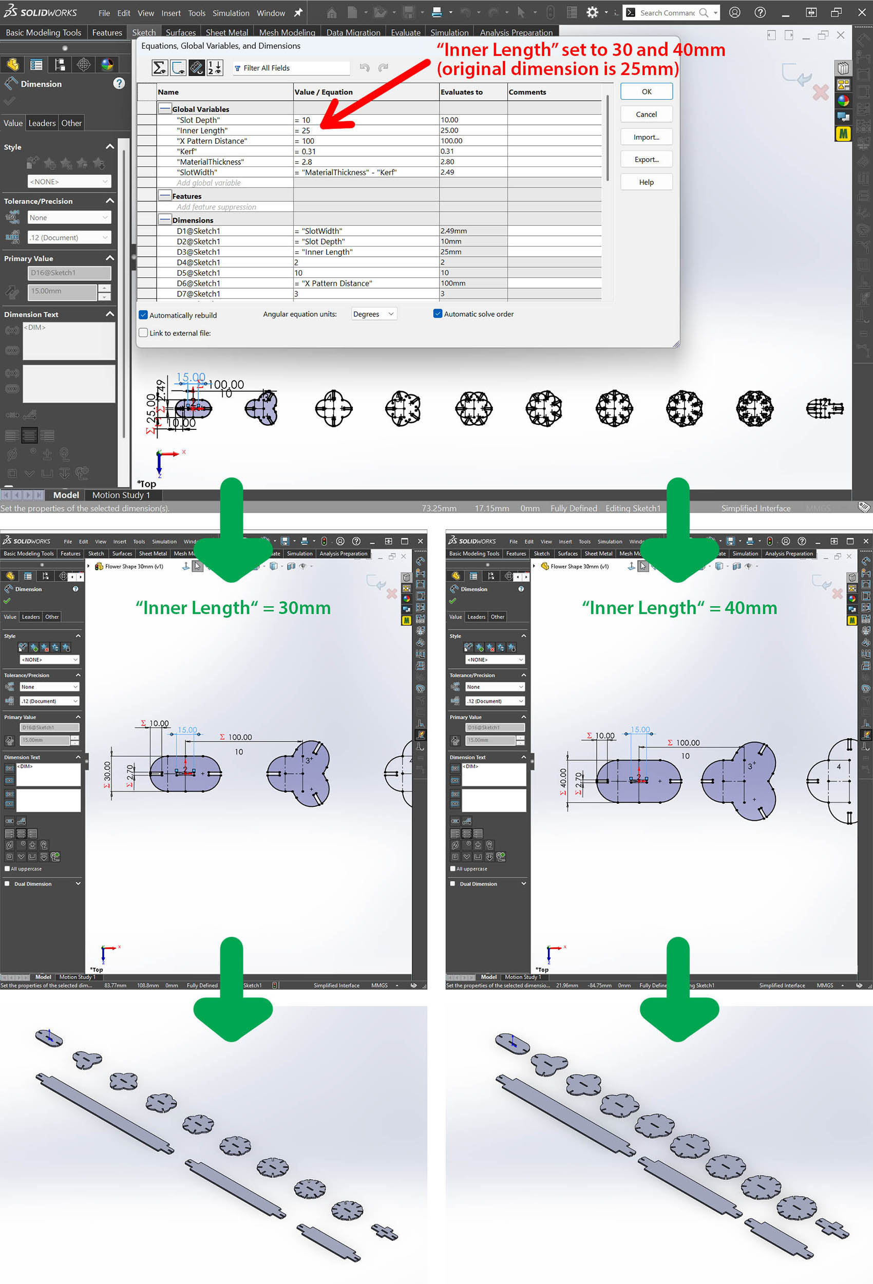
The joint dimensions did not change size along with the parts. Slot depth (10 mm) and part spacing (100 mm) stayed the same, and the slot width is still calculated from material thickness and kerf rather than from the part size. This means the three sizes share the same joint and can be mixed in one structure: a 25 mm flower can connect to a 40 mm flower.
8. Create the Solidworks Drawing File (.SLDDRW)
To prepare the cutting file, I made a SolidWorks drawing (.SLDDRW) called "Flower Shape 25-30-40mm". I inserted each part file as its own drawing view (Drawing View1–3, one for each size) and arranged the three kits in rows on one sheet.
I marked each flower with its number of slots (222, 333, 444 … XXX for 10) so the parts are easy to sort after cutting. The sticks have a pattern of cuts on a separate "Bending Cuts" layer, which [makes them flexible so they can bend into curved shapes. Keeping outline cuts, bending cuts and labels on separate layers means each can be given its own laser settings (cut or engrave).
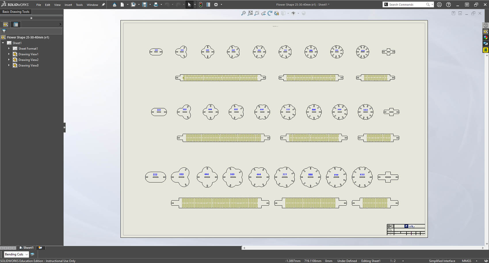
Finally, I exported the drawing as a DXF file to be able to import it into the laser-cut machine "PowerCut" software for cutting.
Laser Cutting: From File to Parts
1. Importing the Drawing
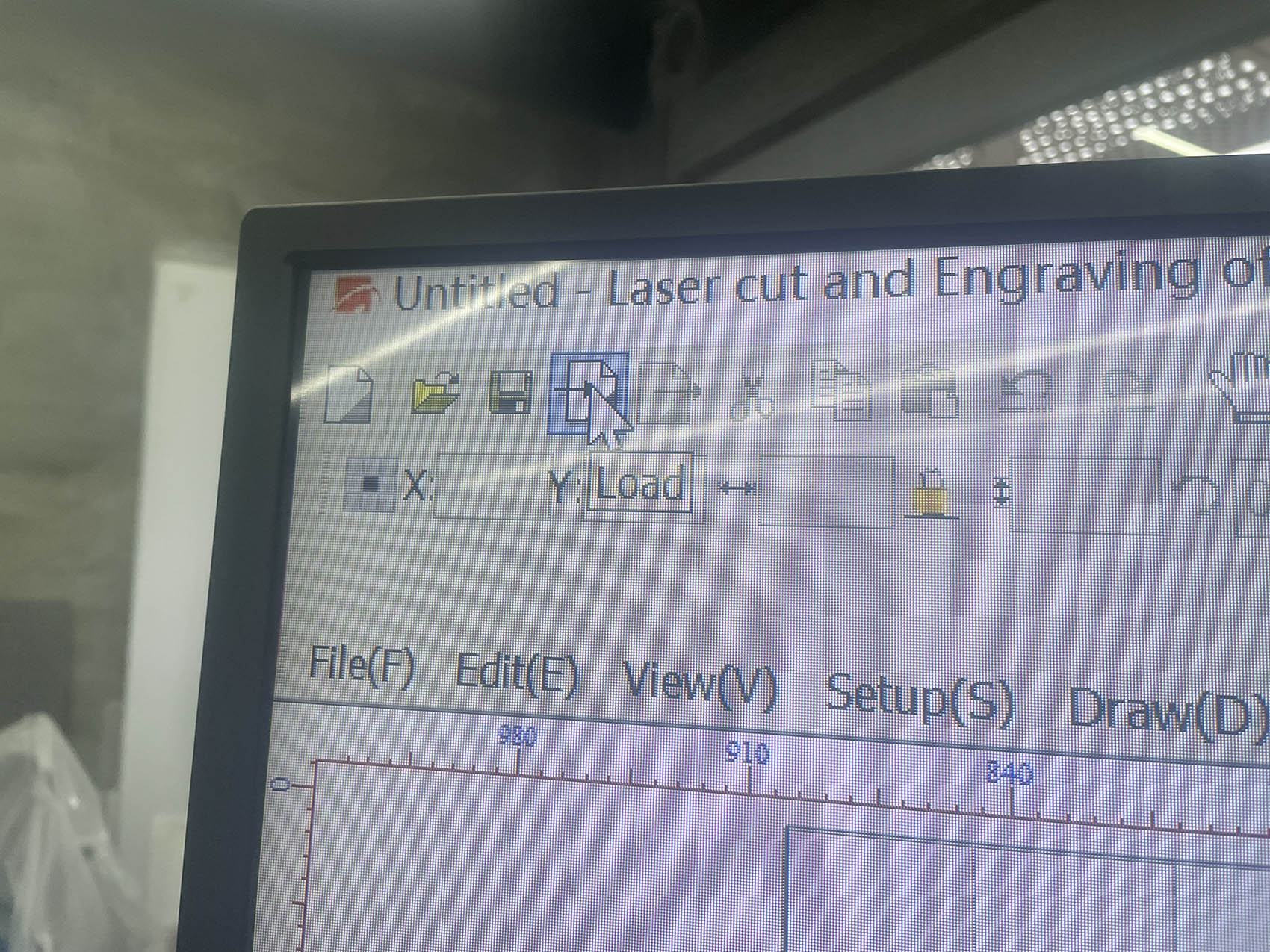
I imported the DXF file into PowerCut with the Load command. After importing, I checked the size of the parts against the rulers and made sure no lines were doubled, because a doubled line is cut twice and burns the edges.
2. Layer Settings: Cut and Engrave
Below is the "Layer Setting" window, PowerCut assigns laser settings by line colour. The dark layers are cut, and the green layer is engraved:
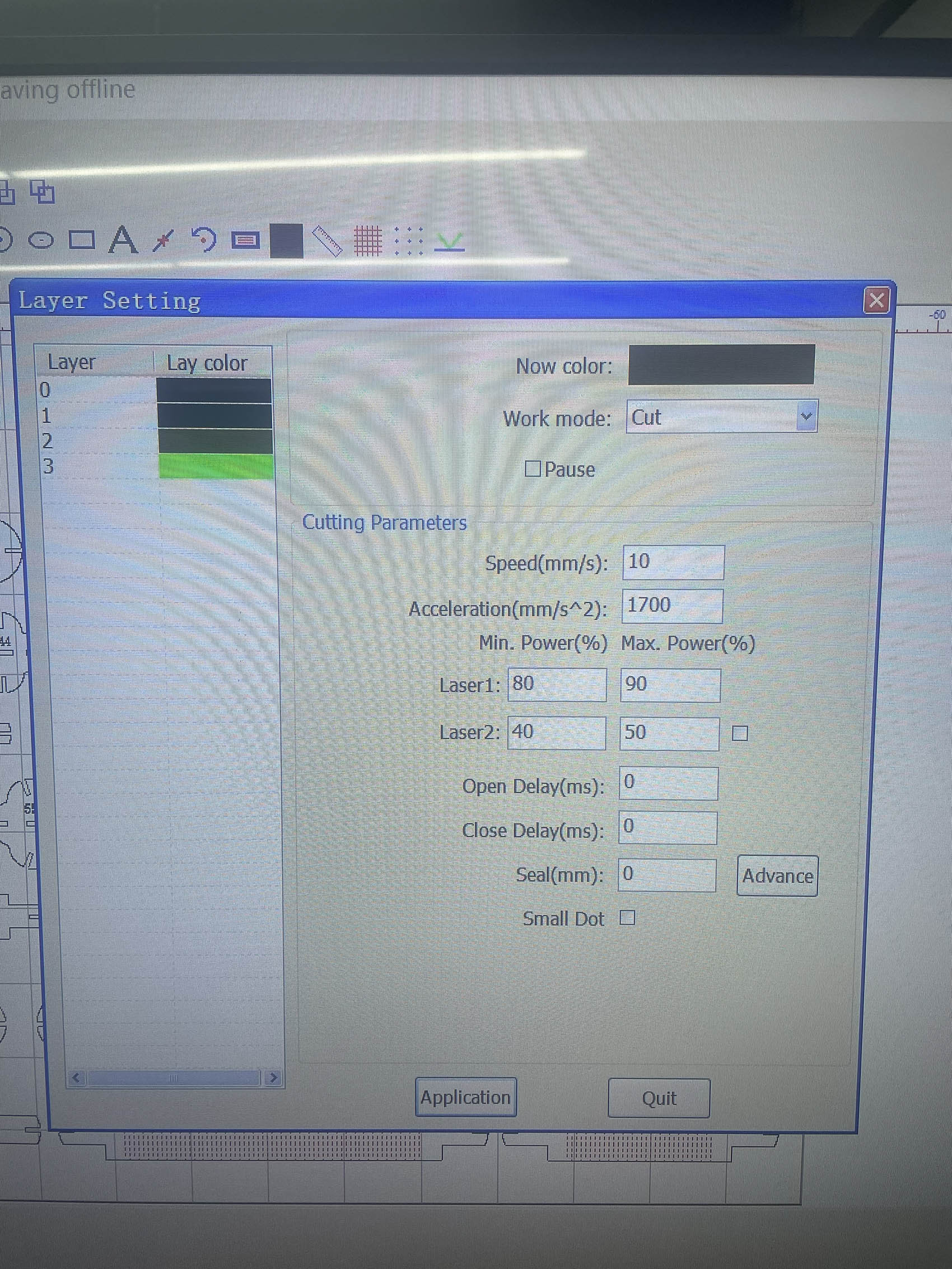
My file used four layers:
- Layers 0–2 (dark), Cut: outlines, slots and the hatched bending cuts on the sticks, all cut right through.
- Layer 3 (green), Engraving: the slot-number labels (222, 333 … XXX), marked on the surface only.
| Setting | Cut (layers 0–2) | Engrave (layer 3) |
|---|---|---|
| Work mode | Cut | Engraving |
| Speed | 10 mm/s | 250 mm/s |
| Acceleration | 1700 mm/s² | 500 mm/s² |
| Laser 1 power (min/max) | 80 / 90 % | 15 / 20 % |
| Laser 2 power (min/max) | 40 / 50 % | 40 / 30 % |
| Engraving step | - | 0.3 mm |
| Engraving direction | - | Horizontal unidirectional, Up First |
A slow speed (10 mm/s) at high power was needed to cut right through the acrylic in one pass. The engraving layer uses a much higher speed and low power, so the numbers are only frosted onto the surface.
3. Sending the Job to the Machine
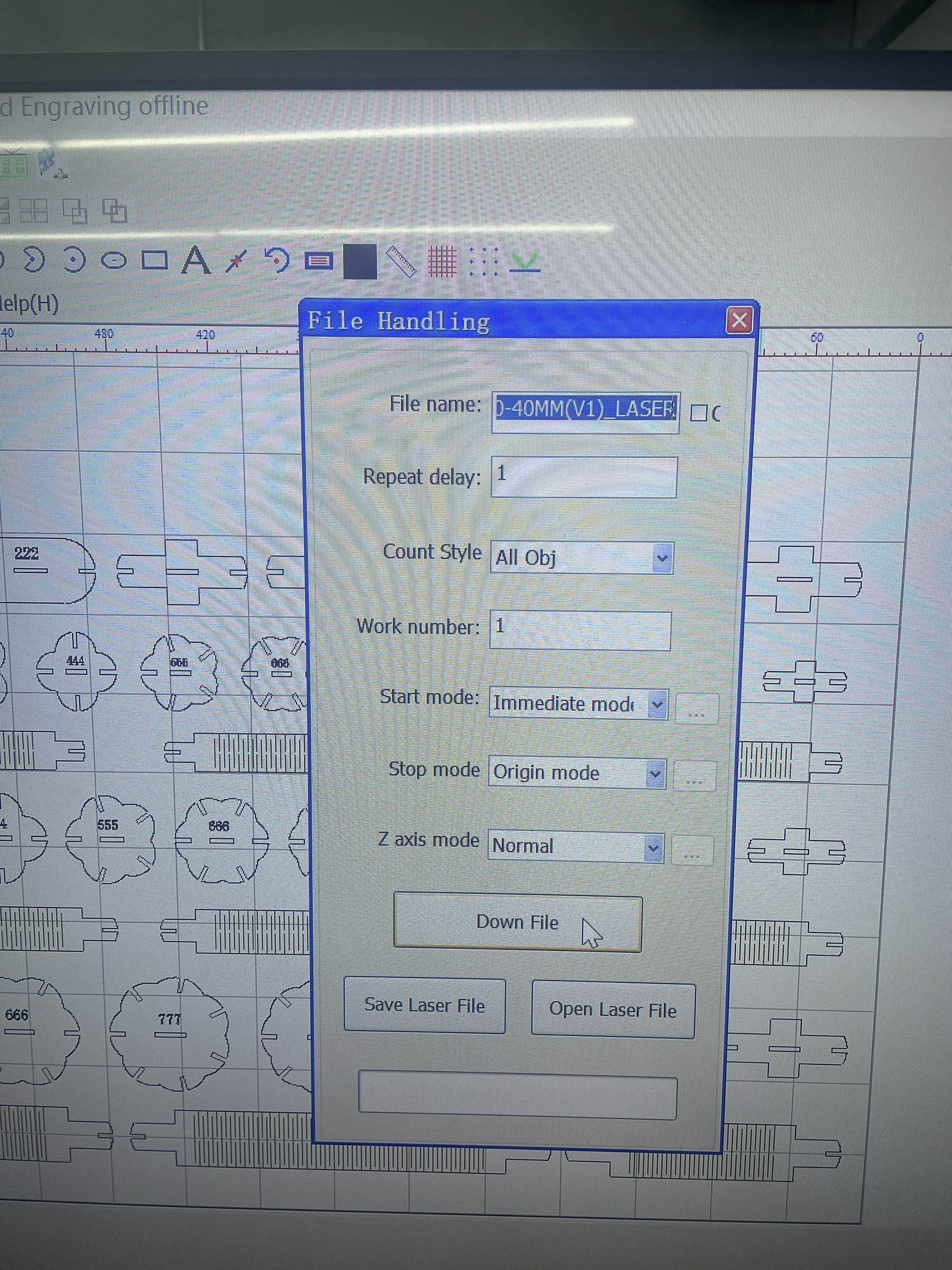
In the File Handling window I named the job (FLOWER1 - the original name was too long), set Work number to 1, Start mode to Immediate and Stop mode to Origin, so the laser head returns to its starting point when the job finishes. I then pressed Down File to send the job to the machine's controller over USB.
4. Setting Up on the Machine
On the machine I...
- placed the acrylic sheet flat on the honeycomb bed;
- set the focus on the material surface;
- moved the head to the start corner with the arrow keys and set the Origin;
- pressed Frame to trace the outline of the job and check that it fitted on the sheet;
- closed the lid, checked that the extraction was running, and started the job once downloaded.
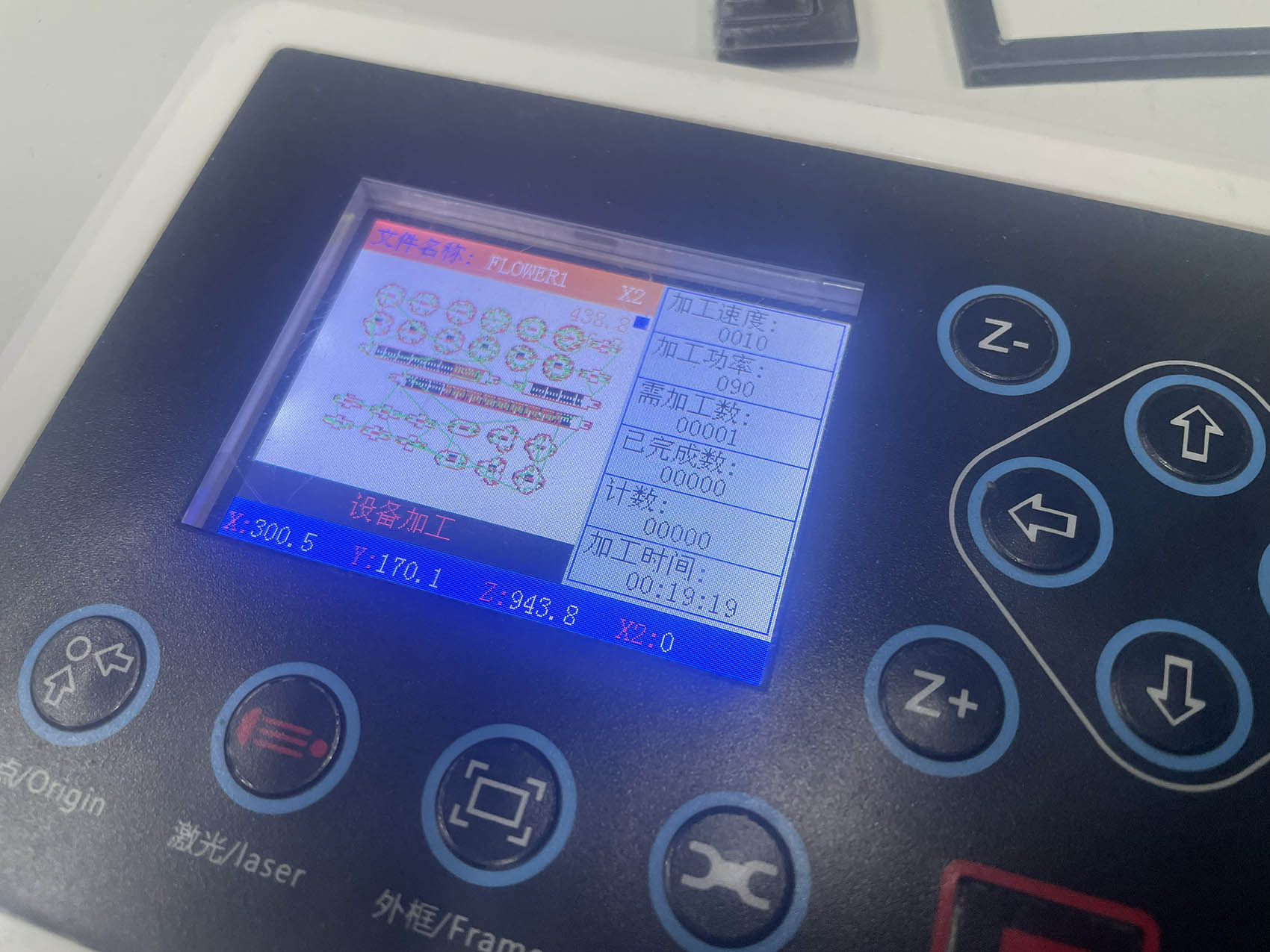
Here is the job "FLOWER1" loaded on the control panel, showing speed 10 and power 90:
5. Cutting
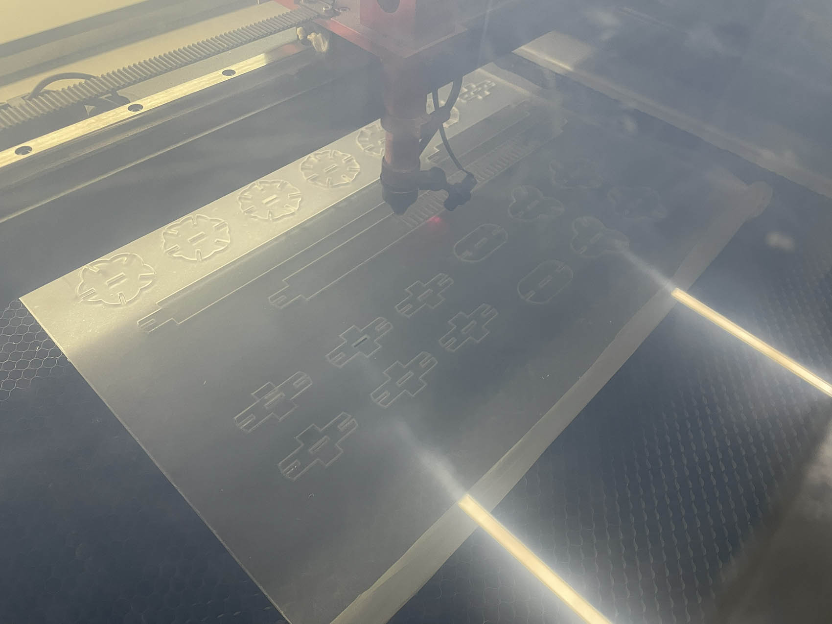
The machine engraved the labels and cut the slots, bending cuts and outlines in a single job. I stayed next to the machine for the whole cut, as the lab's safety rules require.
6. Results & Final Assembly
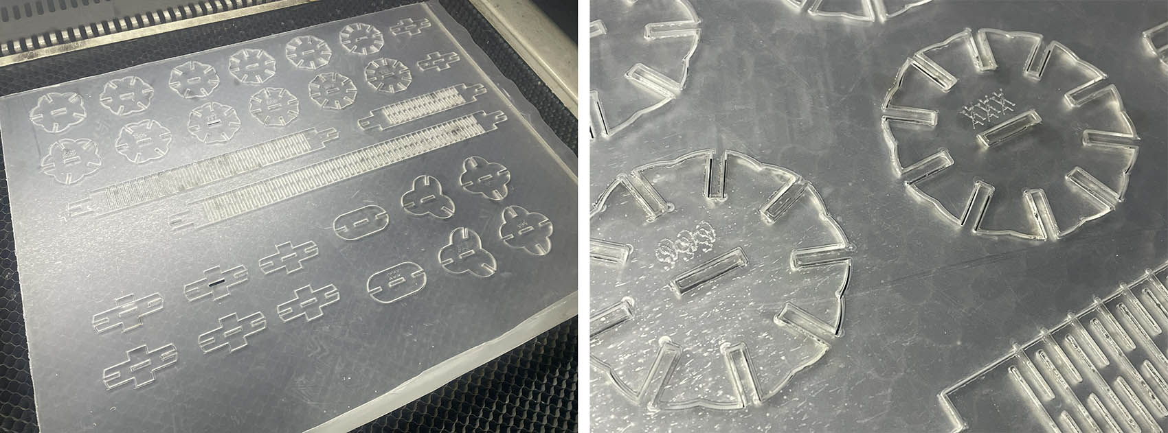
All parts cut through cleanly, with smooth, clear edges. The engraved labels are easy (enough) to read, which made sorting the parts much quicker. The close-up also shows the bending cuts on the sticks.
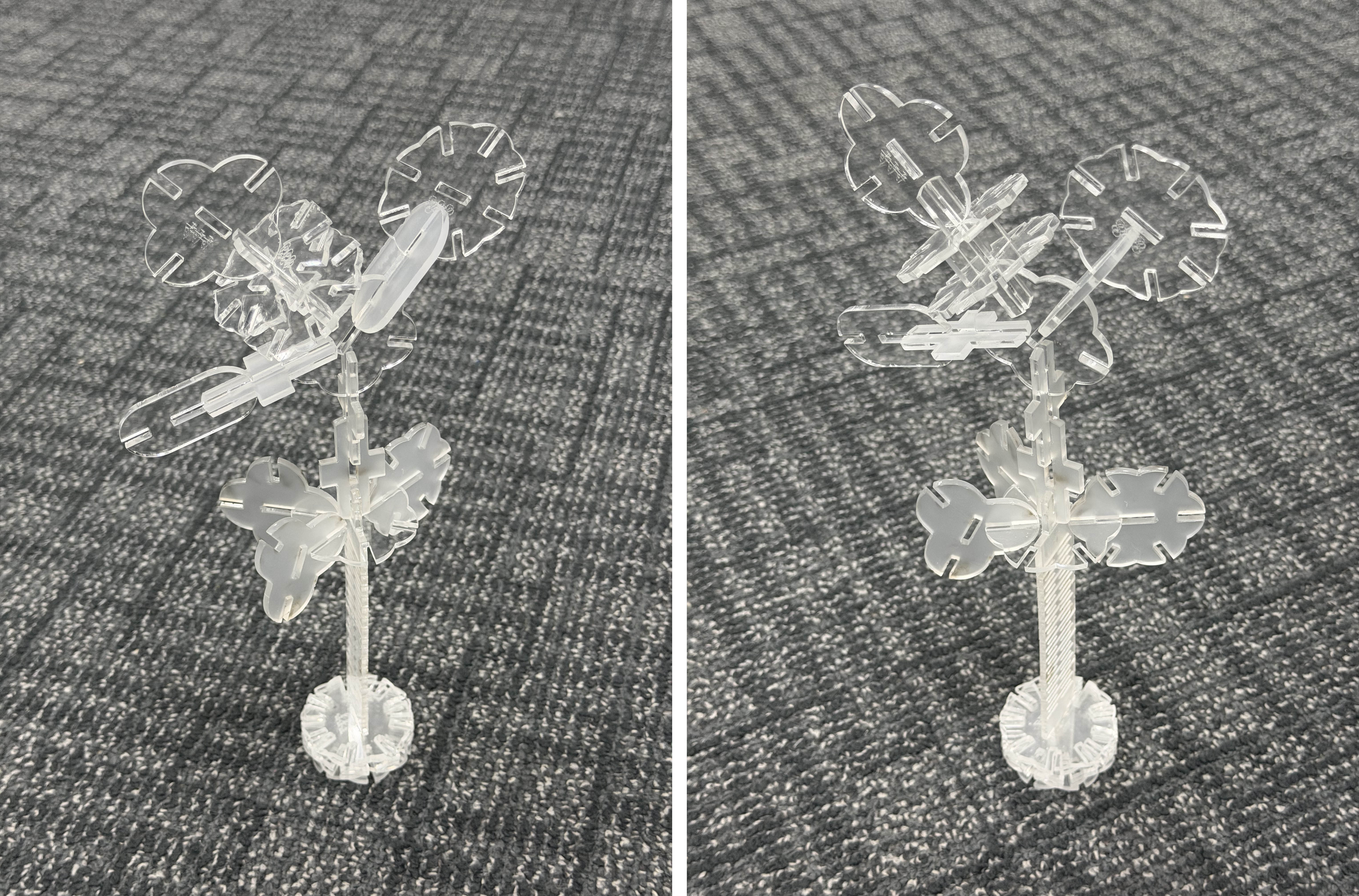
To test the kit, I assembled a free-standing "flower tree". A 10-slot flower is the base, a stick forms the stem, 3- and 4-slot flowers become the leaves and petals, and the connectors form the grid at the top. The whole structure holds together by press fit alone. This "flower tree" is built from the kit, with no glue, other combinations can be created easily (but might need more pieces for more creativity...).
Vinyl Cutter
For the vinyl cutting part of the assignment, I cut my personal logo ("loïcfaulon – Product Designer & Teacher") in blue adhesive vinyl on the Roland DG GS2-24 vinyl cutter, using Roland CutStudio. I made two trials: first one large logo, then a second job with the same logo in several sizes. I then applied one of the stickers to my final project prototype.
1. Preparing the Cut File in CutStudio
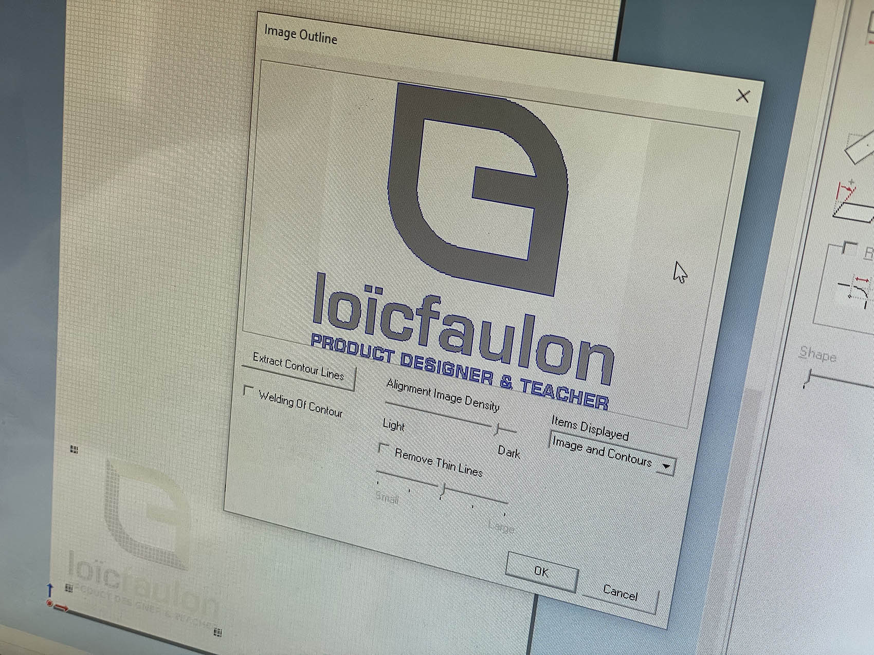
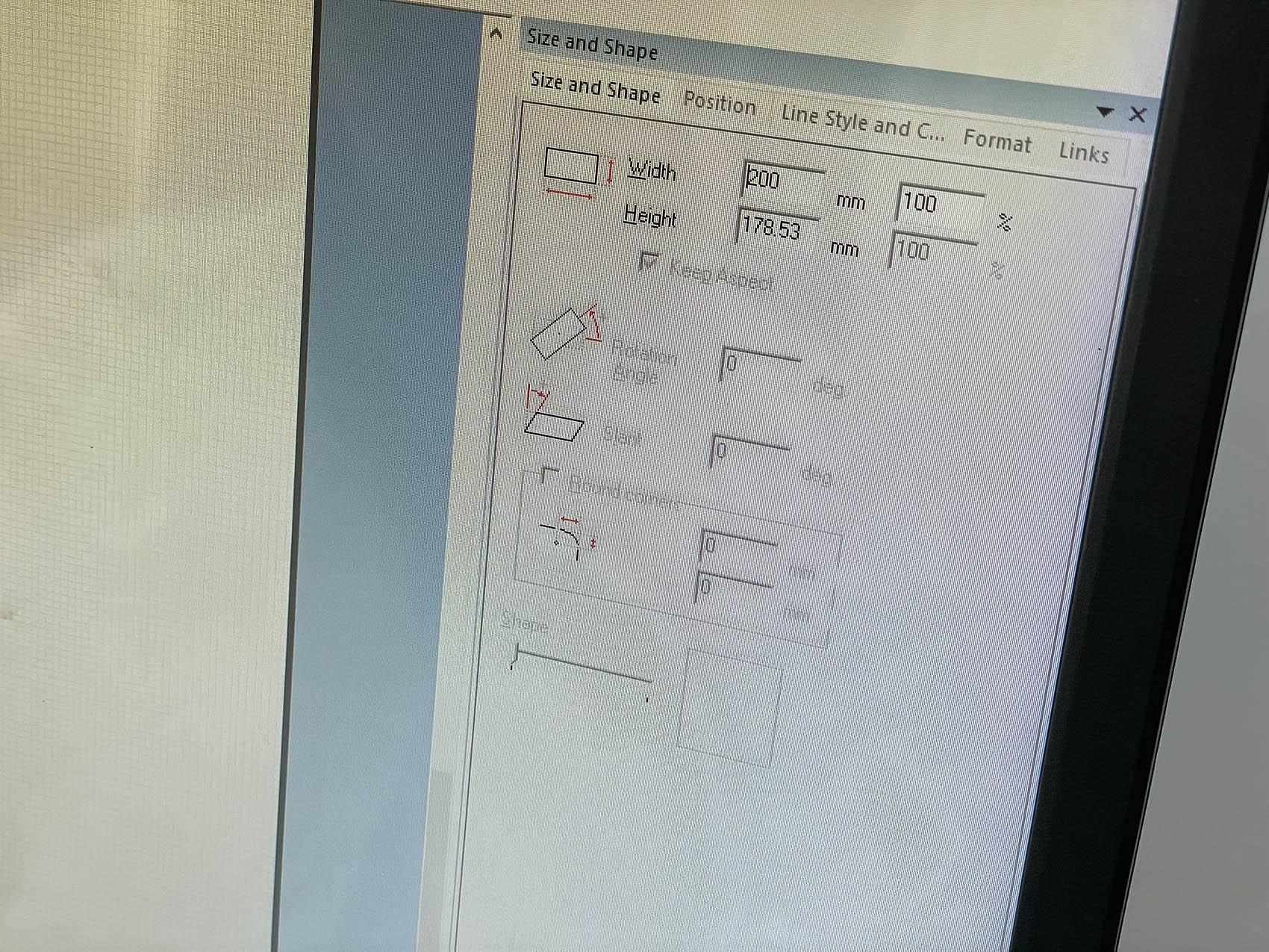
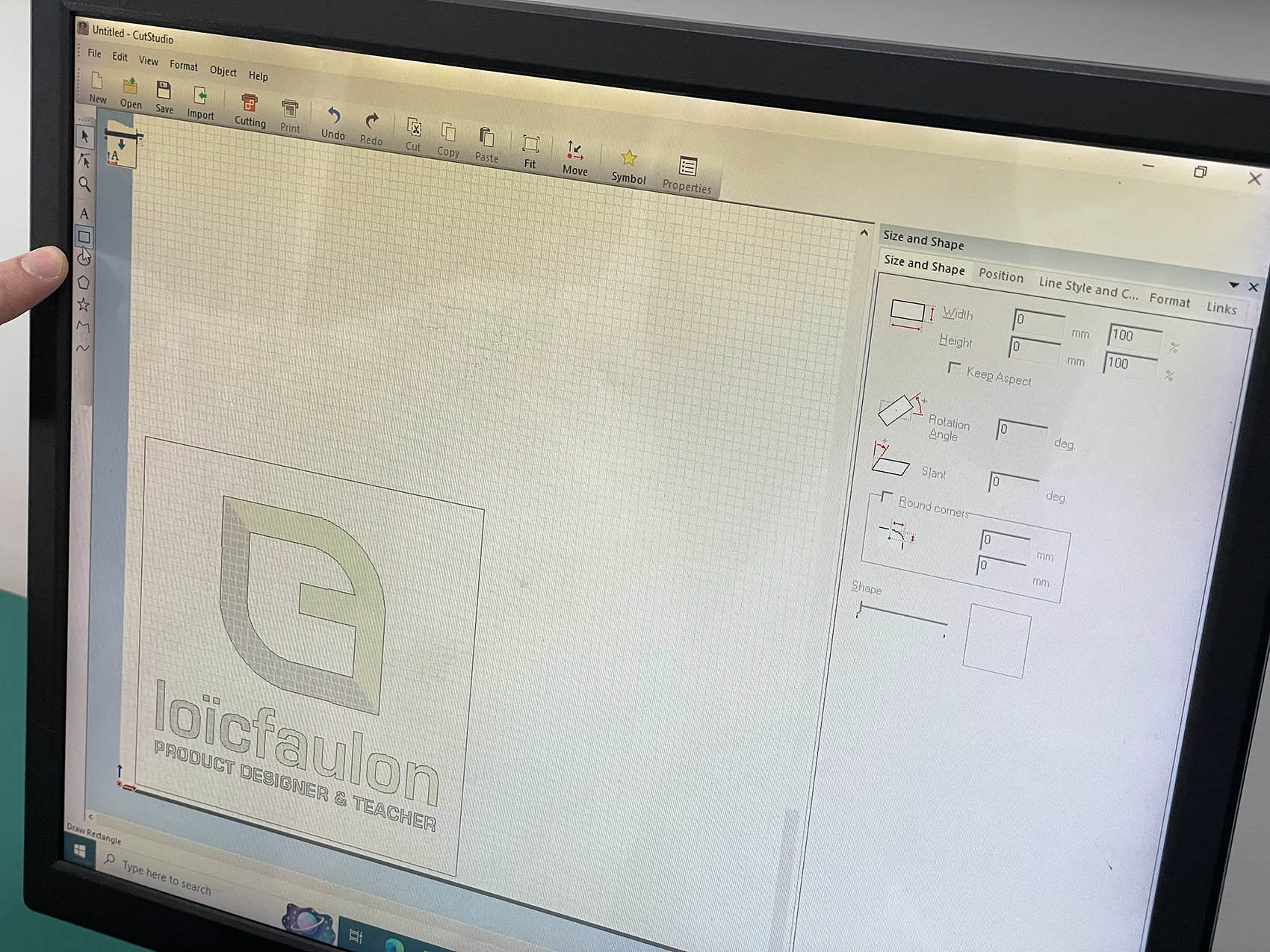
I first designed my logo in Adobe Illustrator and exported it as a high-resolution image (BMP, 300 dpi). In Roland CutStudio I imported this file (File → Import). An image can't be cut directly, so I right-clicked it and used Image Outline, then Extract Contour Lines, to turn the logo into vector cut paths. The preview shows the extracted contour in blue around each letter and the "G" symbol. In the Size and Shape panel I scaled the logo to 200 mm wide (178.53 mm high), with Keep Aspect turned on so it wasn't distorted. Finally, I drew a rectangle around the logo with the Rectangle tool. This gives a weeding border that makes it easier to peel the extra vinyl away later.
Importing the 300 dpi BMP of my logo into CutStudio
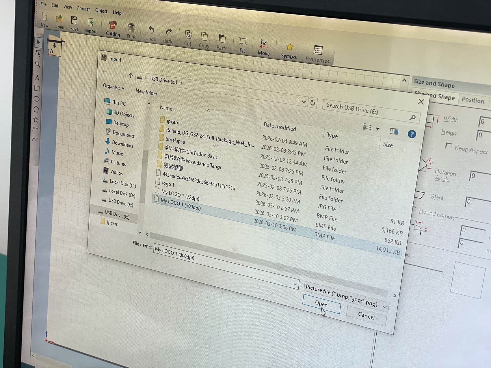
Image Outline: extracting contour lines from the logo image to make vector cut paths
Size and Shape: logo scaled to 200 × 178.53 mm, with aspect ratio locked
The contour logo with a rectangular weeding border, ready to cut
2. Cutting: Two Trials
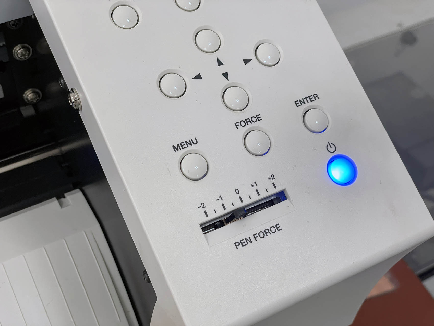
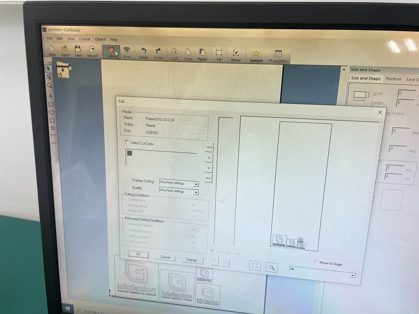
Before cutting, I loaded the blue vinyl roll into the machine and set the cutting force with the PEN FORCE slider on the control panel. In CutStudio I clicked Cutting, checked the machine was listed as Roland DG GS2-24 – Ready (USB), and kept Overlap Cutting and Quality on Machine settings. The preview in the Cut window shows where the job sits on the vinyl before I confirm with OK.
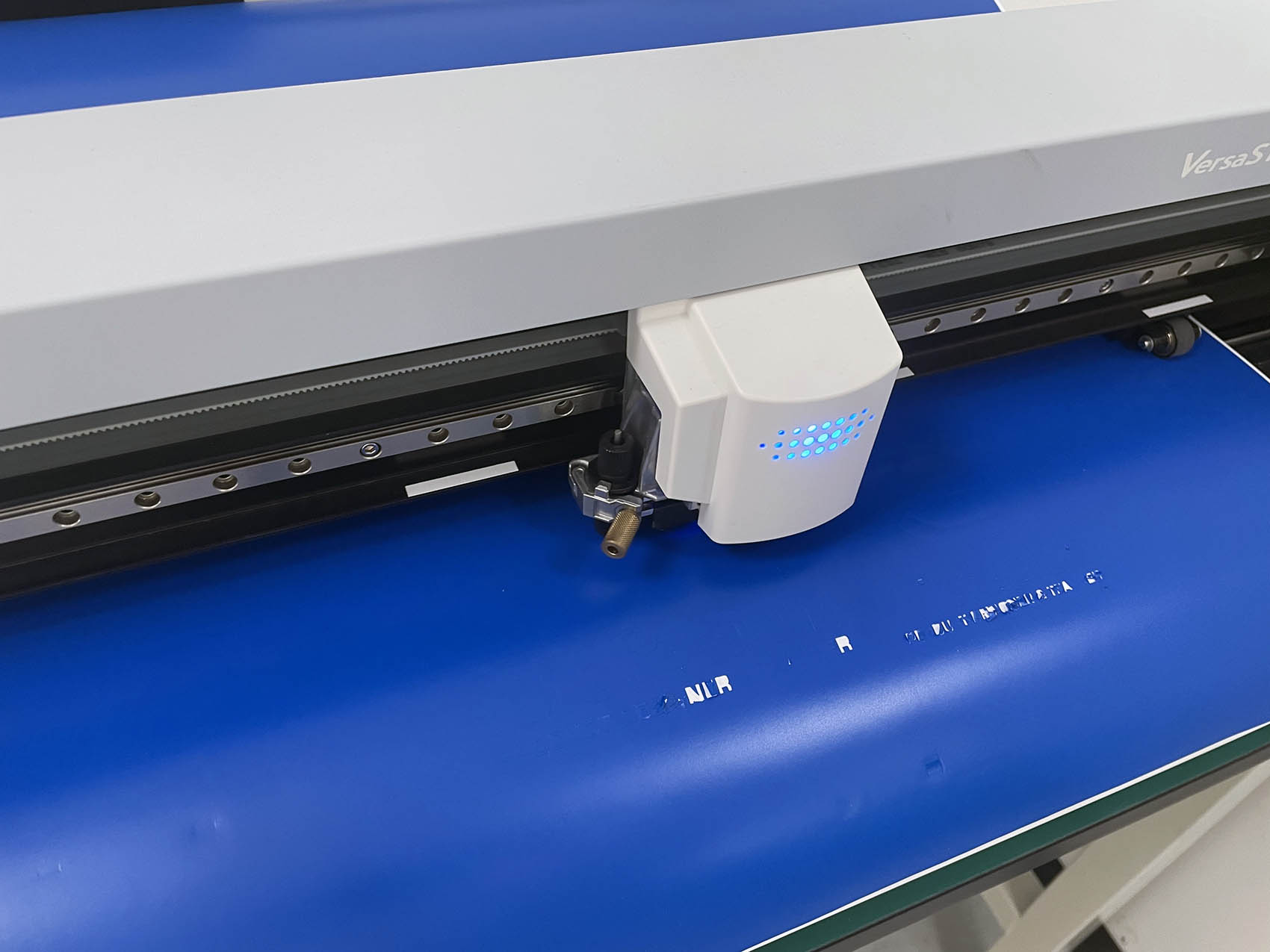
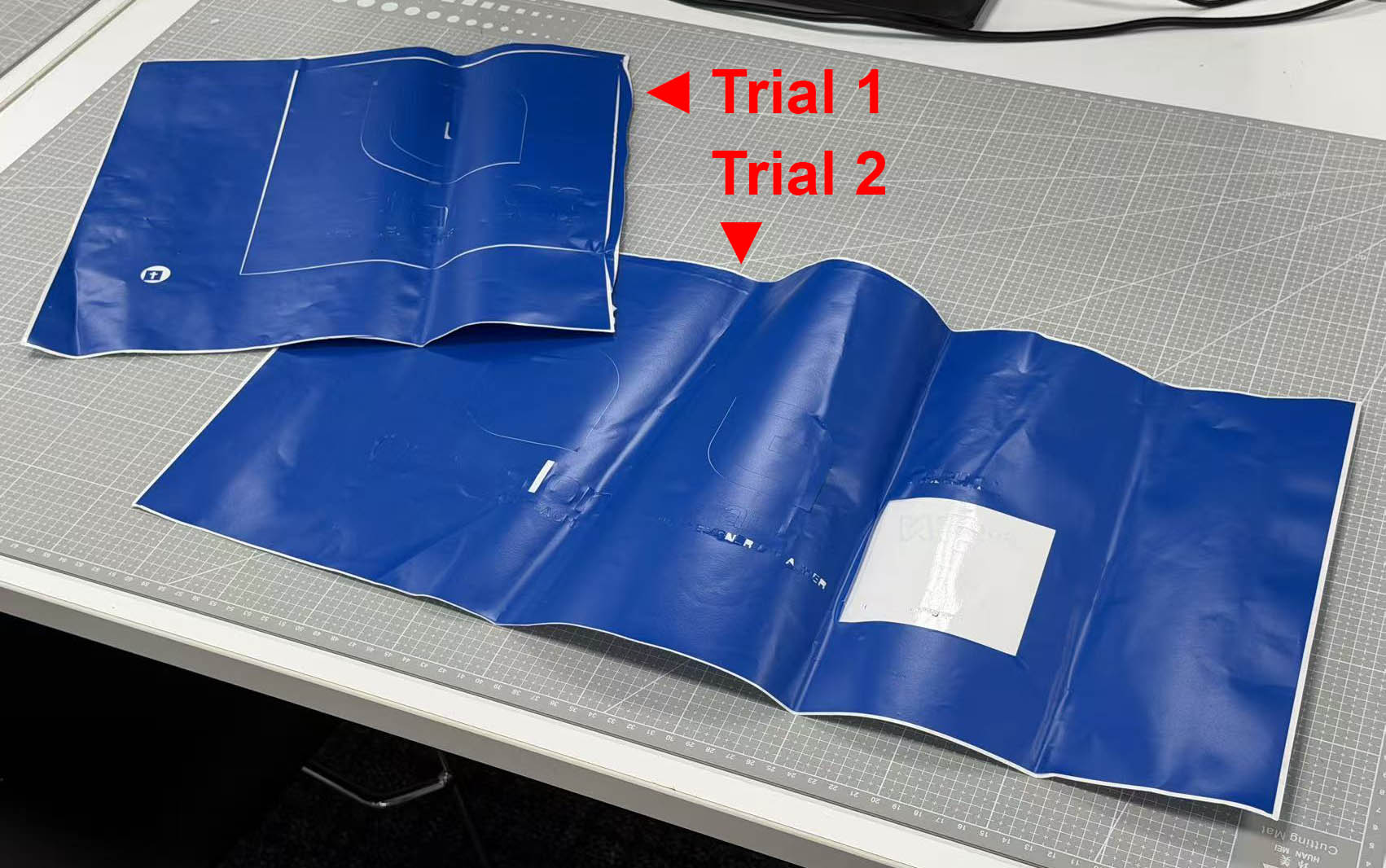
Trial 1: I cut one large logo (200 mm wide). The blade cut too deep: it went through the vinyl and the backing paper in some areas, so the cut was not usable as a sticker. The vinyl should be cut through while the backing paper stays intact, so the design stays in place for weeding.
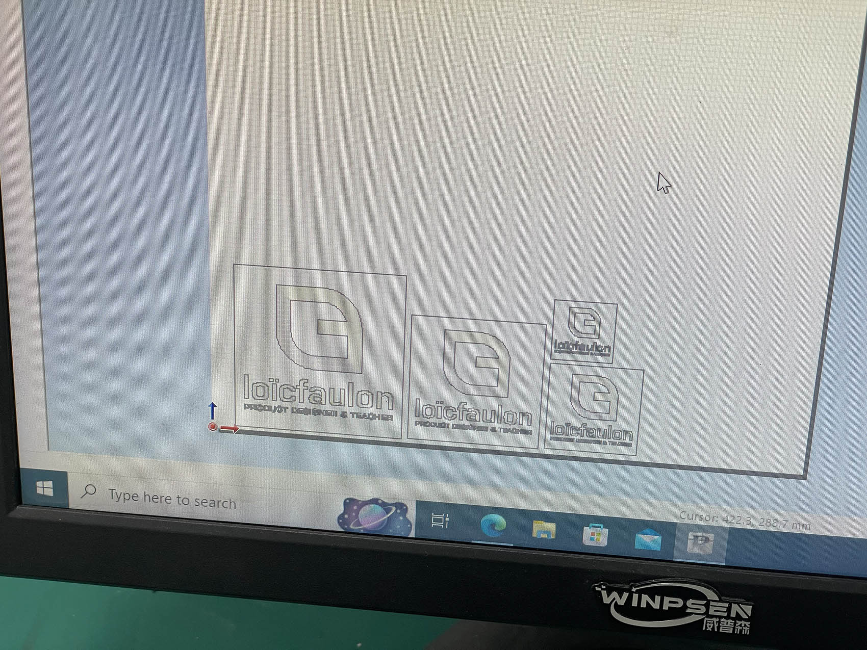
Trial 2: I reduced the pen force so the blade cut only the vinyl. I then made one job with four copies of the logo in different sizes, each with its own weeding border. They were placed close together in the corner of the sheet to save vinyl. This time the backing paper was not cut through. The job also showed me how small the logo can go before the thin "PRODUCT DESIGNER & TEACHER" text gets too fine to cut and weed cleanly.
Trial 1 result: the blade cut through the vinyl and the backing paper
Control panel of the GS2-24: the PEN FORCE slider sets the blade pressure
Cut window: machine ready, and a preview of the four sizes placed in the corner of the vinyl
Trial 2 layout: the same logo in four sizes in one job
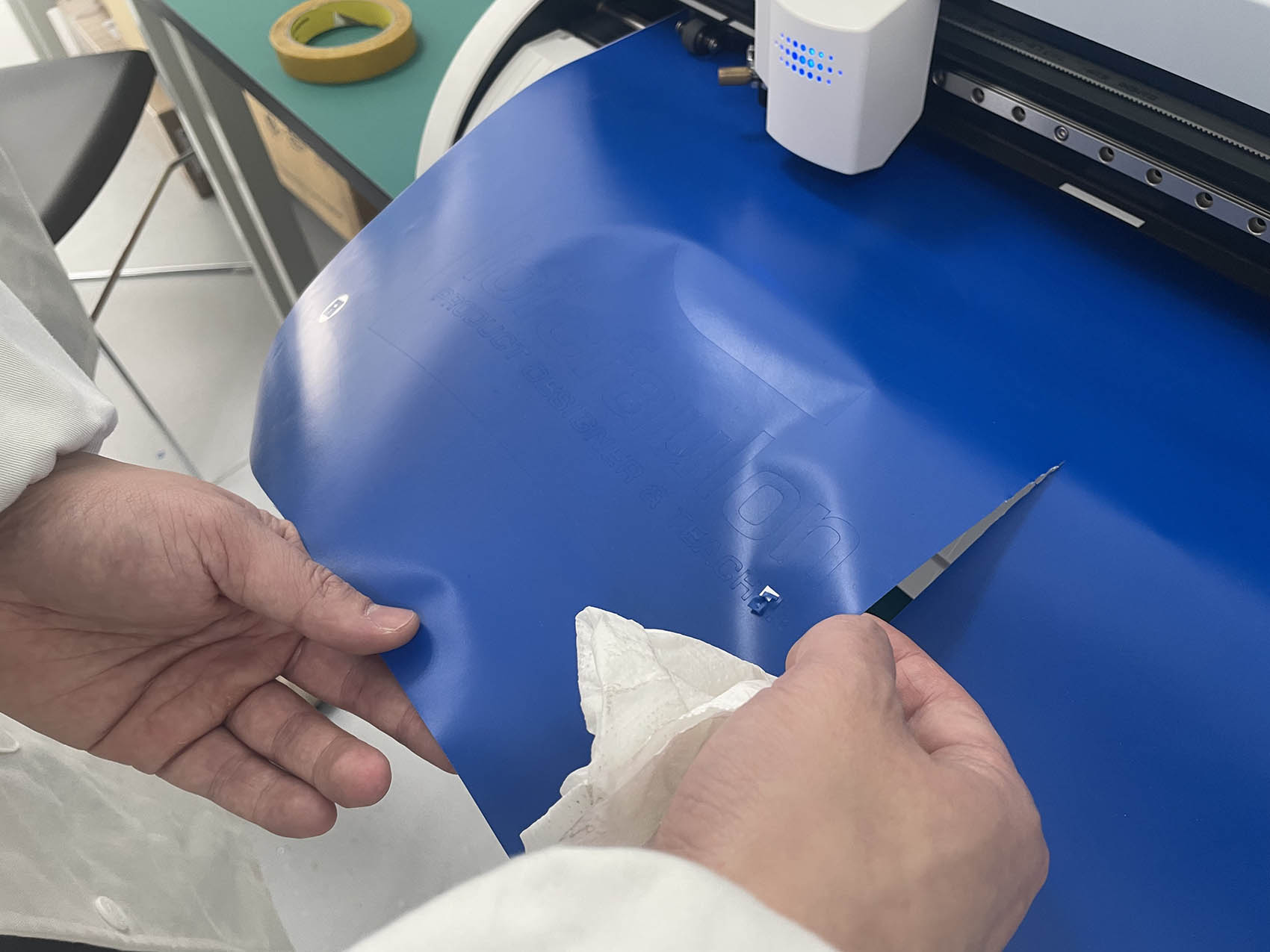
The vinyl cutter cutting the Trial 2 job
Video of the cutting in progress
3. Weeding and application
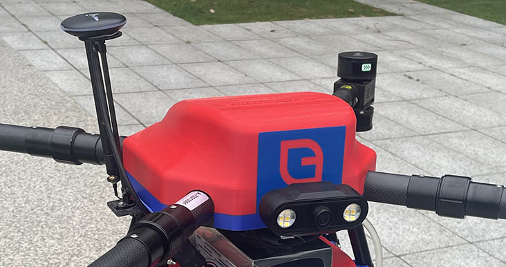
After cutting, I pulled the vinyl out of the machine and cut the job away from the roll. Then I weeded it, peeling off the vinyl I didn't need so that only the logo stayed on the backing paper. Weeding the small letters and the inner parts of the letters (such as the "o", "a" and the dot of the "ï") was the most delicate step. I then transferred one of the logos onto the red cover of my final project prototype.
(add Trial 2 Photo of the whole sticker)
The vinyl cutter cutting the Trial 2 job
What I learned: The pen force has to be set so the blade cuts the vinyl but not the backing paper. A test cut before the real job saves material. Tracing a bitmap with Image Outline is quick, but fine details such as small text push the limits of the process. Cutting the same design in several sizes in one job is a cheap way to find the smallest size that can still be cut and weeded well. A weeding border around each design makes peeling much easier.