Appearance
WEEK 9 – Input Devices
Assignments
Group Assignment
- Probe an input device's analog levels and digital signals
Individual Assignment
- Measure something: add a sensor to a microcontroller board that you have designed and read it
Group Work
Our group work is accessible HERE (add the link)
Individual Work
PART ONE 😃
While waiting for the machining of my "ROUND 5" PCB extension board from Week 8 "PCB Production", I decided to use breadboard to start my task for Week 9 Input Devices. Once my PCB board from Week 8 is complete, I will transfer most of the components to it.
Here is the list of the main components used (microcontroller and input devices):
- Xiao ESP32-S3 Series / Xiao ESP32-S3 Sense (including Camera)
- Ultrasonic Sensor (model HC-SR04)
- Rotation Sensor
- 6*6 Push Button Switch
- Relay (model JOC-3FF-S-Z / output device)
Use Scenario:
This is a draft scenario which could relate to my final project, it is supposed to...
- Detect if the "object" is within a certain distance of the sensor (e.g. distance between the agricultural drone and the crops to be treated with pesticide)
- Detect the deseases of the plants based on colour (in our case here, I have chosen red as being the critical color to activate the action)
- Both of the above mentioned conditions must be met to activate the action (e.g. Activating a pump to spray pesticide on the crops)
- Additionally, I have added a manual control which can allow to switch-off-or-on the possibility to dimm-down-or-up an LED light (for my final project, this could be used to switch on or off a manual crontrol to increase or decrease the flow of pesticides to be delivered depending on human decision)
Pin Assignment Plan:
| Pins (IAO-ESP32-S3) | Signal Name |
|---|---|
| D0 | 6*6 Puch Button Switch |
| A1 | Ultrasonic Sensor TRIG |
| A2 | Ultrasonic Sensor ECHO + Resitor 1000 Ω |
| D4 | Relay IN |
| A5 | Rotational Sensor OUT |
| D6 | LED + |
| GND | Ultrasonic Sensor / Rotational Sensor / Relay / LED - / Ultrasonic Sensor ECHO + Resitor 2000 Ω |
| VCC | Ultrasonic Sensor / Rotational Sensor / Relay / 6*6 Push Button Switch |
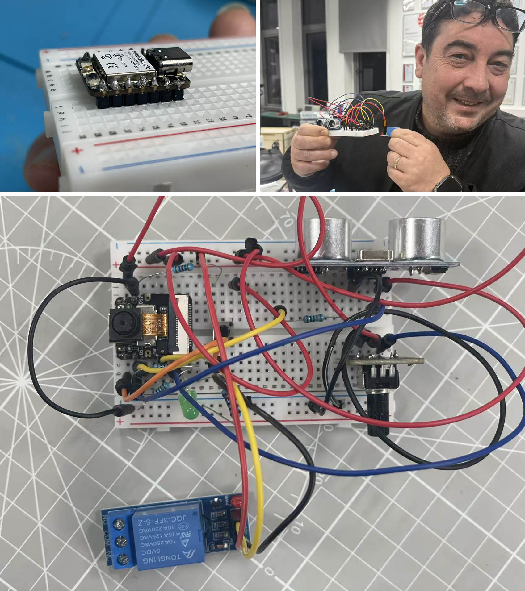
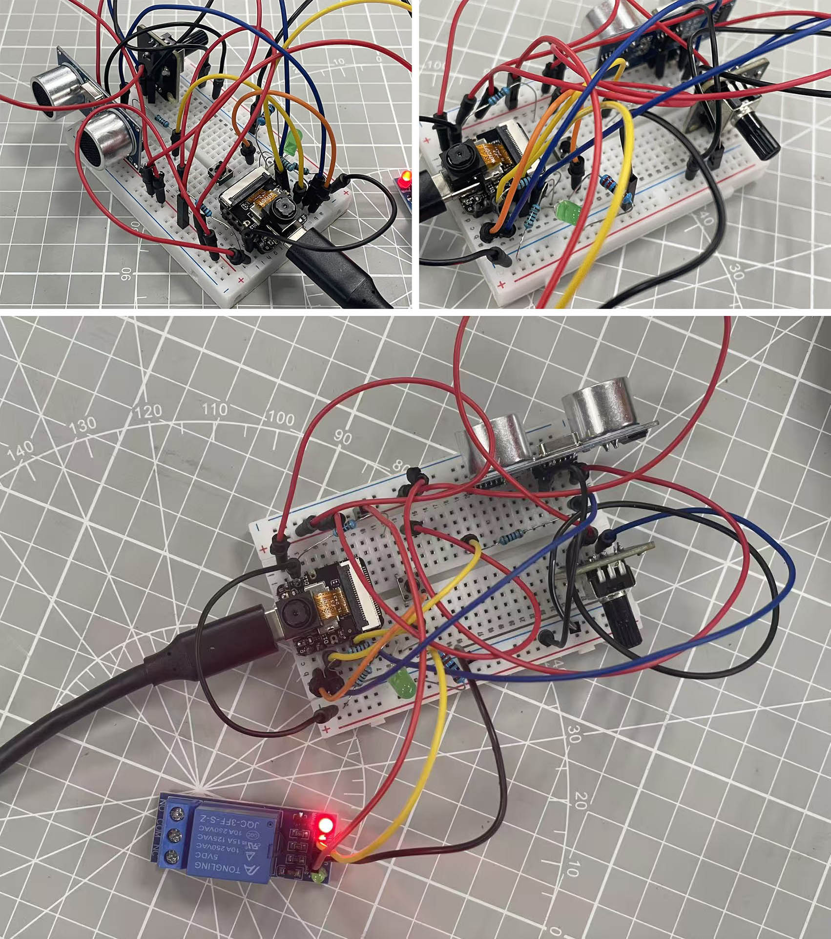
Breadboard assembly:
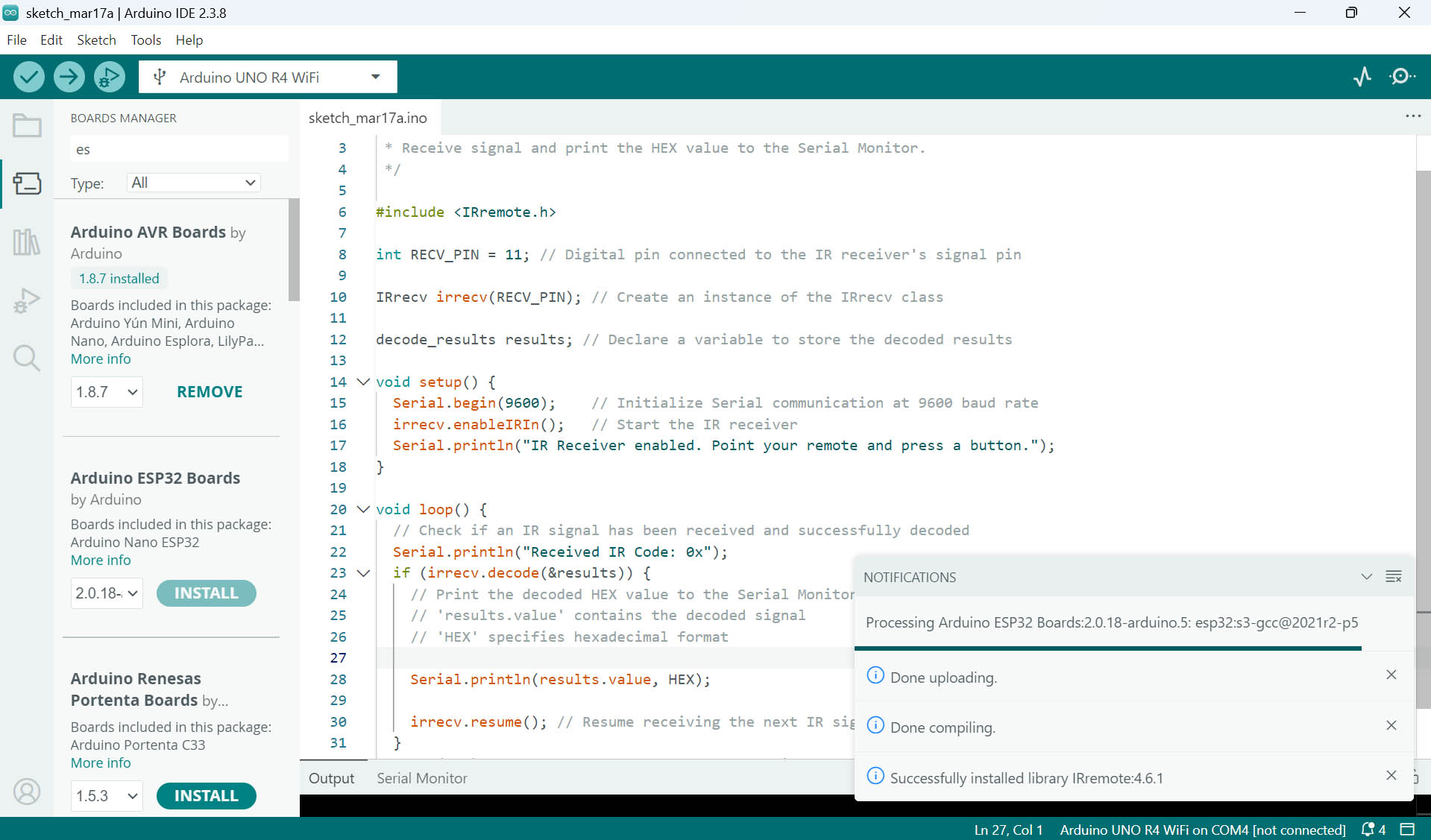
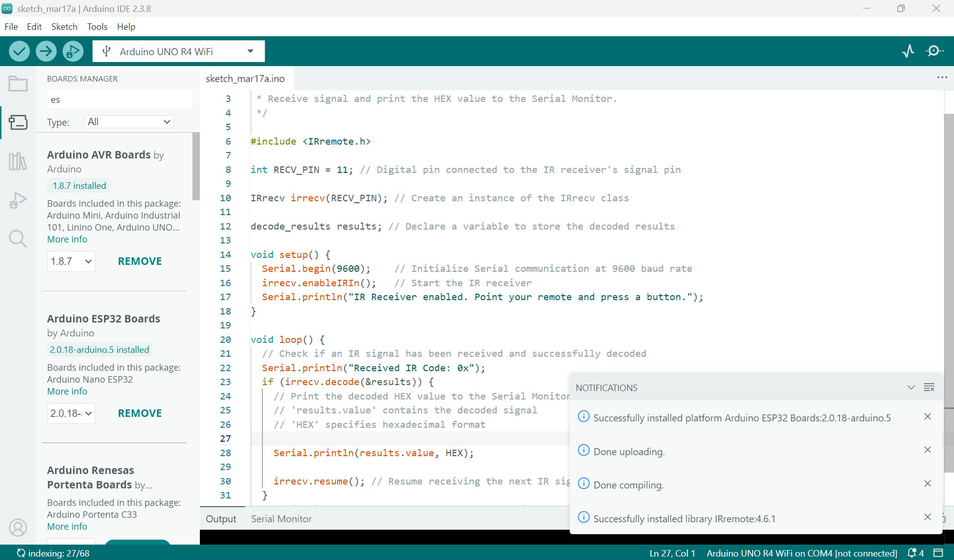
Getting Arduino IDE ready for Xiao ESP32:
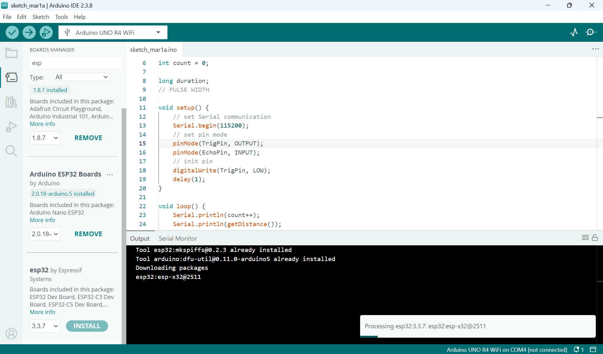
First, I need to install the Platform for Arduino ESP32 Boards in Arduino IDE (picture 1&2). Then, I need to install the Board Manager for ESP32 by Espressif Systems (picture 3).
Final codes for Arduino IDE generated with the help of Gemini AI:
#include "esp_camera.h"
#include <Arduino.h>

// --- Pin Definitions ---
#define PIN_LED      D6
#define PIN_ROTARY   D5
#define PIN_RELAY    D4
#define PIN_BUTTON   D0
#define PIN_TRIG     D1
#define PIN_ECHO     D2

// --- Camera Pins for XIAO ESP32-S3 ---
#define PWDN_GPIO_NUM     -1
#define RESET_GPIO_NUM    -1
#define XCLK_GPIO_NUM     10
#define SIOD_GPIO_NUM     40
#define SIOC_GPIO_NUM     39
#define Y9_GPIO_NUM       48
#define Y8_GPIO_NUM       11
#define Y7_GPIO_NUM       12
#define Y6_GPIO_NUM       14
#define Y5_GPIO_NUM       16
#define Y4_GPIO_NUM       18
#define Y3_GPIO_NUM       17
#define Y2_GPIO_NUM       15
#define VSYNC_GPIO_NUM    38
#define HREF_GPIO_NUM     47
#define PCLK_GPIO_NUM     13

// Global States
bool ledMasterSwitch = false;
bool cameraReady = false;

void setup() {
  Serial.begin(115200);
  while(!Serial);

  Serial.println("\n--- System Boot: Dual Logic Mode ---");

  // Initialize Pins
  pinMode(PIN_LED, OUTPUT);
  pinMode(PIN_RELAY, OUTPUT);
  pinMode(PIN_BUTTON, INPUT_PULLUP); // Active LOW
  pinMode(PIN_TRIG, OUTPUT);
  pinMode(PIN_ECHO, INPUT);

  // Camera Configuration
  camera_config_t config;
  config.ledc_channel = LEDC_CHANNEL_0;
  config.ledc_timer = LEDC_TIMER_0;
  config.pin_d0 = Y2_GPIO_NUM;
  config.pin_d1 = Y3_GPIO_NUM;
  config.pin_d2 = Y4_GPIO_NUM;
  config.pin_d3 = Y5_GPIO_NUM;
  config.pin_d4 = Y6_GPIO_NUM;
  config.pin_d5 = Y7_GPIO_NUM;
  config.pin_d6 = Y8_GPIO_NUM;
  config.pin_d7 = Y9_GPIO_NUM;
  config.pin_xclk = XCLK_GPIO_NUM;
  config.pin_pclk = PCLK_GPIO_NUM;
  config.pin_vsync = VSYNC_GPIO_NUM;
  config.pin_href = HREF_GPIO_NUM;
  config.pin_sscb_sda = SIOD_GPIO_NUM;
  config.pin_sscb_scl = SIOC_GPIO_NUM;
  config.pin_pwdn = PWDN_GPIO_NUM;
  config.pin_reset = RESET_GPIO_NUM;
  config.xclk_freq_hz = 20000000;
  config.frame_size = FRAMESIZE_QVGA;
  config.pixel_format = PIXFORMAT_RGB565;
  config.grab_mode = CAMERA_GRAB_LATEST;
  config.fb_location = CAMERA_FB_IN_PSRAM;
  config.fb_count = 1;

  esp_err_t err = esp_camera_init(&config);
  if (err == ESP_OK) {
    cameraReady = true;
    Serial.println("Camera: ONLINE");
  } else {
    Serial.printf("Camera: FAILED 0x%x\n", err);
  }
}

// Function to analyze color at frame center
bool isRedDetected() {
  if (!cameraReady) return false;

  camera_fb_t * fb = esp_camera_fb_get();
  if (!fb) return false;

  uint32_t r_sum = 0, g_sum = 0, b_sum = 0;
  int samples = 0;
  uint8_t *data = fb->buf;

  int cx = fb->width / 2;
  int cy = fb->height / 2;

  // Sample 20x20 area at center
  for (int y = cy - 10; y < cy + 10; y++) {
    for (int x = cx - 10; x < cx + 10; x++) {
      int i = (y * fb->width + x) * 2;

      // ESP32-S3 Byte Order Correction
      uint8_t b1 = data[i];     // High Byte
      uint8_t b2 = data[i+1];   // Low Byte

      // Convert 565 to 0-255
      r_sum += (b1 & 0xF8);
      g_sum += ((b1 & 0x07) << 5) | ((b2 & 0xE0) >> 3);
      b_sum += (b2 & 0x1F) << 3;
      samples++;
    }
  }

  int r = r_sum / samples;
  int g = g_sum / samples;
  int b = b_sum / samples;

  Serial.printf("RGB:[%d,%d,%d] ", r, g, b);

  esp_camera_fb_return(fb);

  // Detection Logic: Red must be dominant (1.3x higher than G/B)
  return (r > 80 && r > (g * 1.3) && r > (b * 1.3));
}

void loop() {
  // 1. LED Control (Independent of Relay)
  static bool lastBtn = HIGH;
  bool currBtn = digitalRead(PIN_BUTTON);
  if (lastBtn == HIGH && currBtn == LOW) {
    ledMasterSwitch = !ledMasterSwitch;
    Serial.print("\nLED Master: "); Serial.println(ledMasterSwitch ? "ON" : "OFF");
    delay(150);
  }
  lastBtn = currBtn;

  int rot = analogRead(PIN_ROTARY);
  analogWrite(PIN_LED, ledMasterSwitch ? map(rot, 0, 4095, 0, 255) : 0);

  // 2. Ultrasonic Measurement
  digitalWrite(PIN_TRIG, LOW); delayMicroseconds(2);
  digitalWrite(PIN_TRIG, HIGH); delayMicroseconds(10);
  digitalWrite(PIN_TRIG, LOW);
  long duration = pulseIn(PIN_ECHO, HIGH, 26000); // 26ms timeout
  float distance = duration * 0.034 / 2;

  bool isNear = (distance > 0 && distance < 25);

  // 3. Camera Color Check
  bool isRed = isRedDetected();

  // 4. Dual Condition Relay Logic (AND)
  Serial.printf("| Dist:%.1fcm | Red:%s | ", distance, isRed ? "YES" : "NO");

  if (isNear && isRed) {
    digitalWrite(PIN_RELAY, HIGH);
    Serial.println(">>> RELAY: ACTIVE <<<");
  } else {
    digitalWrite(PIN_RELAY, LOW);
    // Debug specific missing condition
    if (isNear && !isRed) Serial.println("[WAITING FOR RED]");
    else if (!isNear && isRed) Serial.println("[OBJECT TOO FAR]");
    else Serial.println("[IDLE]");
  }

  delay(200);
}
First Prompt to Gemini AI:
"Can you write me the code for arduino IDE to send to XIAO ESP32-S3 for the following: LED+ is on D6, LED- on GND, Rotational sensor out on D5 (I also connect the VCC and GND), Relay in on D4 (I also connect the VCC and GND), switch 6x6 to D0 (I also connect the VCC and GND), HC-SR04 echo to D2 and trigger to D1 (I also connect the VCC and GND). The rotational sensor should dim up and down the LED. The switch 6x6 should turn on the relay when pressed. The HC-SR04 should turn on the relay when an object is within 25cm distance and light the LED. The camera of the XIAO ESP32-S3 should turn on the relay when it recognizes red and yellow colors (with all other colors it should keep the relay off)."
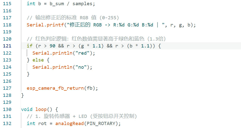
Following other prompts to debug and improve the codes, I also manually refined the RGB settings for identifying the Red color with the microcontroller camera:
Breadboard assembly in action:
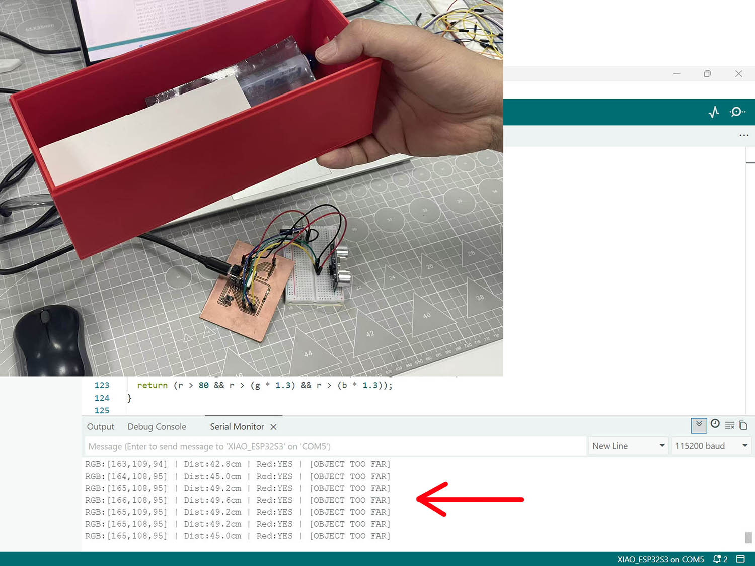
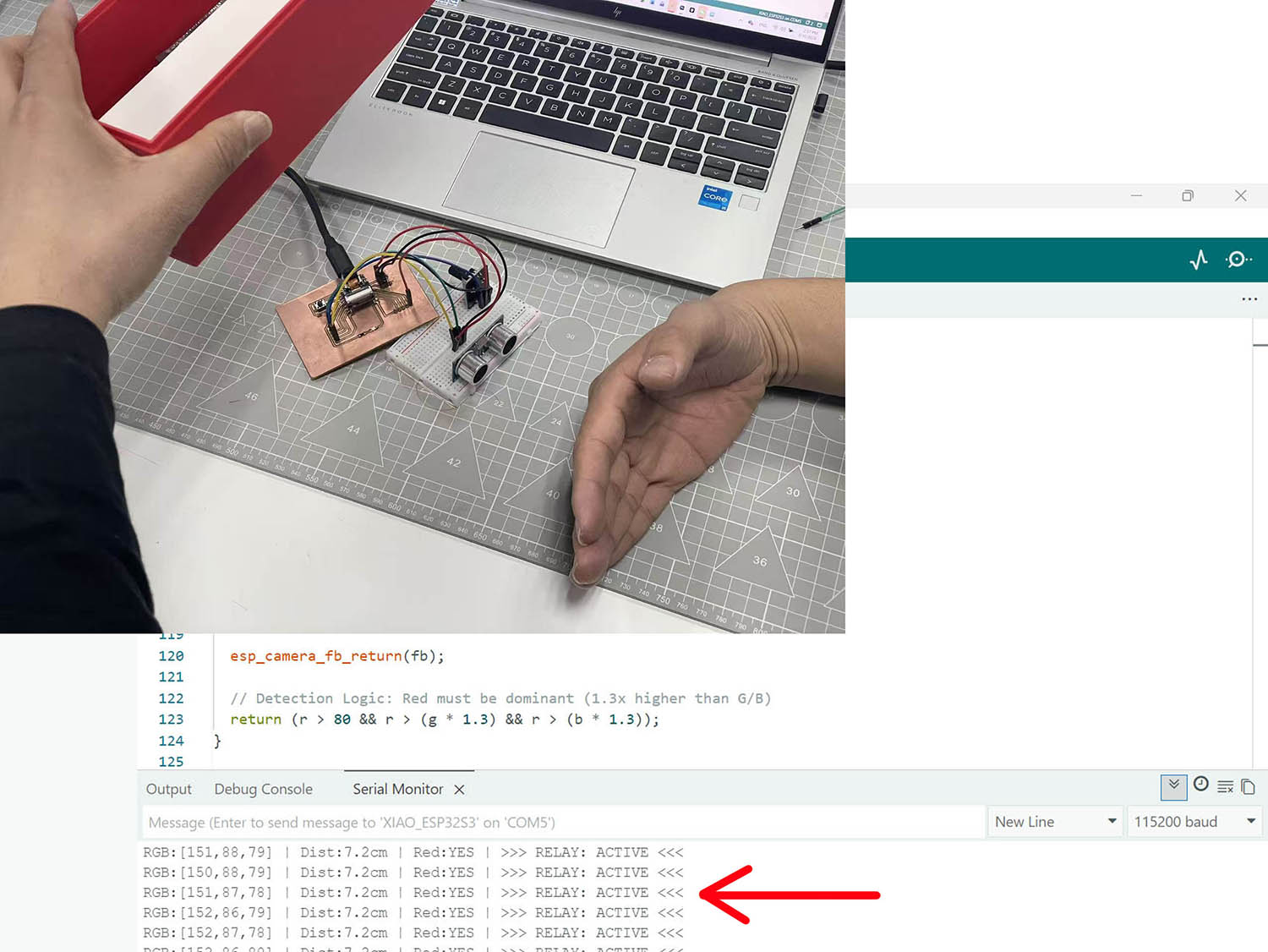
😃 😃 😃 SUCCESFULL DETECTION of the object within 25cm distance of the untrasonic sensor as we can read in Arduino IDE's Serial Monitor Output window "LOOKING FOR RED" intead of "IDLE" originally.
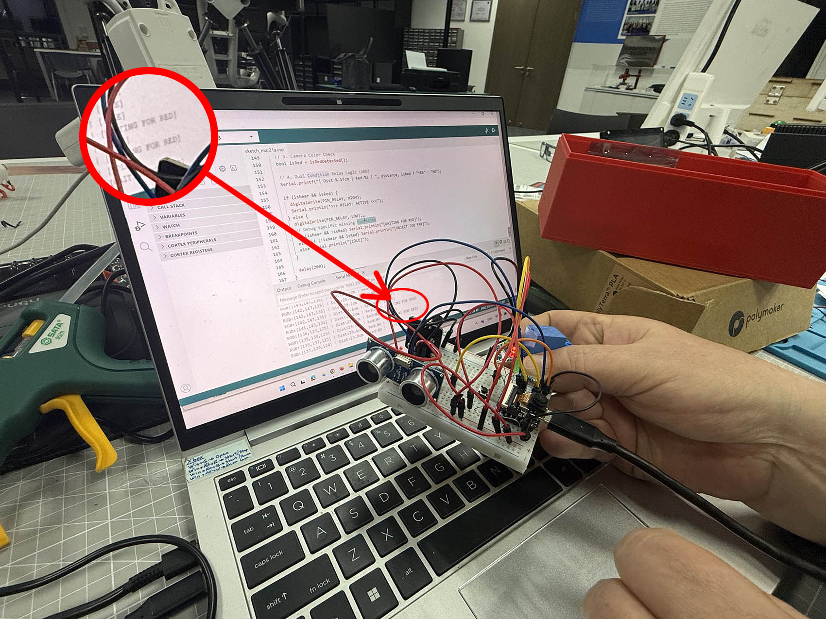
😃 😃 😃 SUCCESSFULL DETECTION of the red colour by the camera as we can read in the Arduino IDE's Serial Monitor Output window "OBJECT TOO FAR" if only the red colour is detected, and "ACTIVE" if booth conditions are fulfilled (Red colour + Object within a 25cm distance).
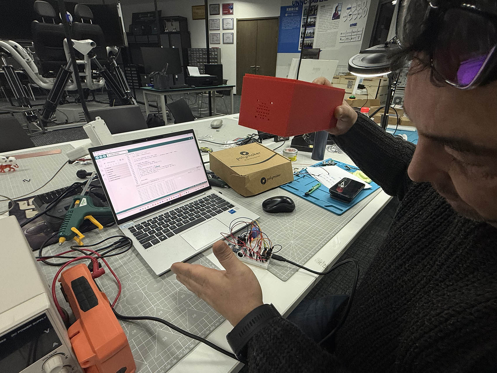
PART TWO 😃
My PCB extension board is now complete with one Xiao ESP32-S3 Sense microprocessor, one LED with one Resistor, one switch with one Resitor, and two 5-Pinhead plus two 3-Pinhead connectors. I use breadboard to help me connect the rest of PART 1 scenario components, such as one Rotational Sensor and one Ultrasonic Sensor, to the PCB extension board.
Pin Assignment Plan:
The pin assignment is the same as for PART 1 at the exception of the LED and Ultrasonic Sensor TRIG which have been inverted as described in the code: 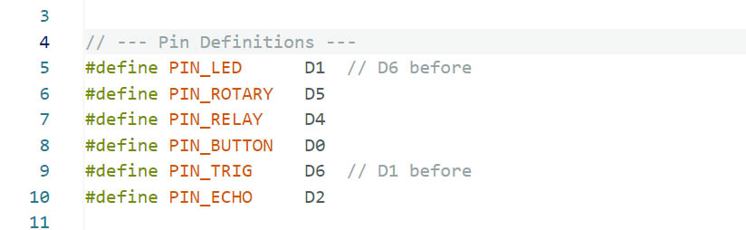
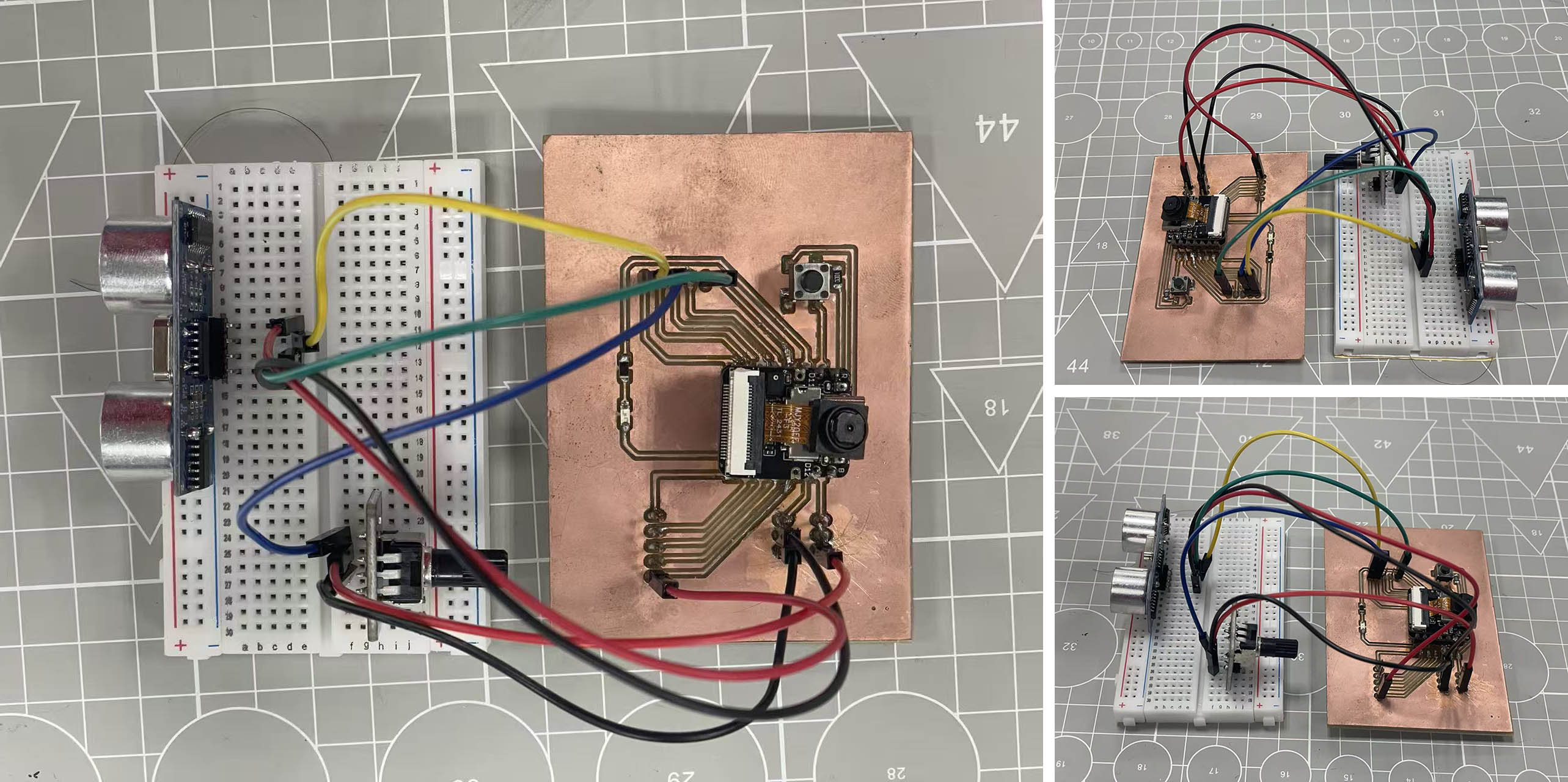
PCB Extension Board Assembly:
(The Relay component is not considered in this assembly as it is an Output Device)
Input Devices in action and reading:
- Object within 25cm of the Ultrasonic sensor:
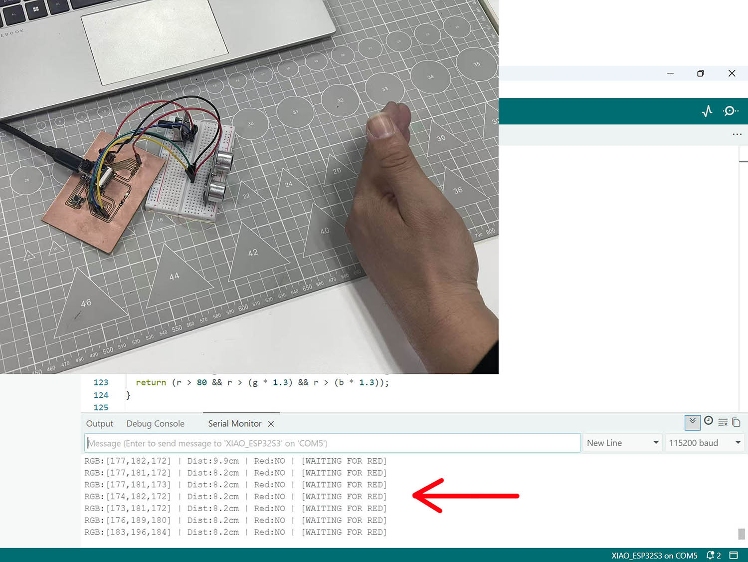
- Red object detected by the Xiao ESP32-S3 Sense camera:
- Object within 25cm + Red colour detected:
- Dimm-down or up the LED light with the Rotational sensor:
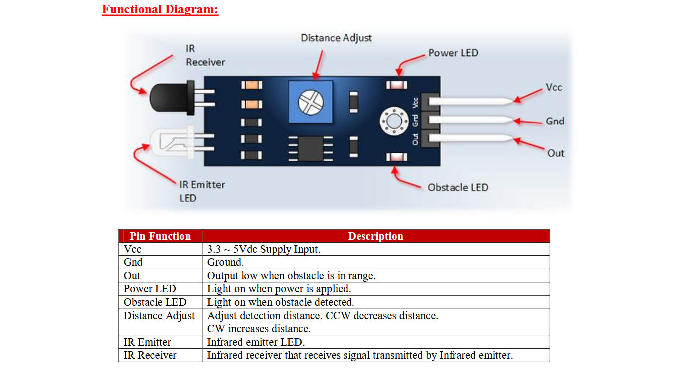
PART THREE 😃
The Ultrasonic sensor HC-SR04 used in PART ONE and PART TWO is in someway out-of-date today... So I decided to test separatly an IR (Infra-red) Obstacle sensor, the Flying-Fish series from MH