Appearance
WEEK 2 – Computer-Aided Design
Individual Assignment
- Model (raster, vector, 2D, 3D, render, animate, simulate, ...) a possible final project, compress your images and videos, and post a description with your design files on your class page.
CAD Software Comparison/Evaluation
The following comparison/evaluation of CAD software is divided in two main sections:
- 3D CAD Software
- 2D CAD Software
3D CAD Software
For the 3D CAD section, I will cover Fusion 360, Solidworks, Rhino 3D, and Autodesk Alias, which represent four distinct approaches to 3D modeling. Fusion 360 is an all-in-one, cloud-based platform for general design and manufacturing. Solidworks is an enterprise-level parametric engineering tool. Rhino 3D is an unconstrained NURBS powerhouse, while Autodesk Alias is the premium gold standard for automotive Class-A surfacing.
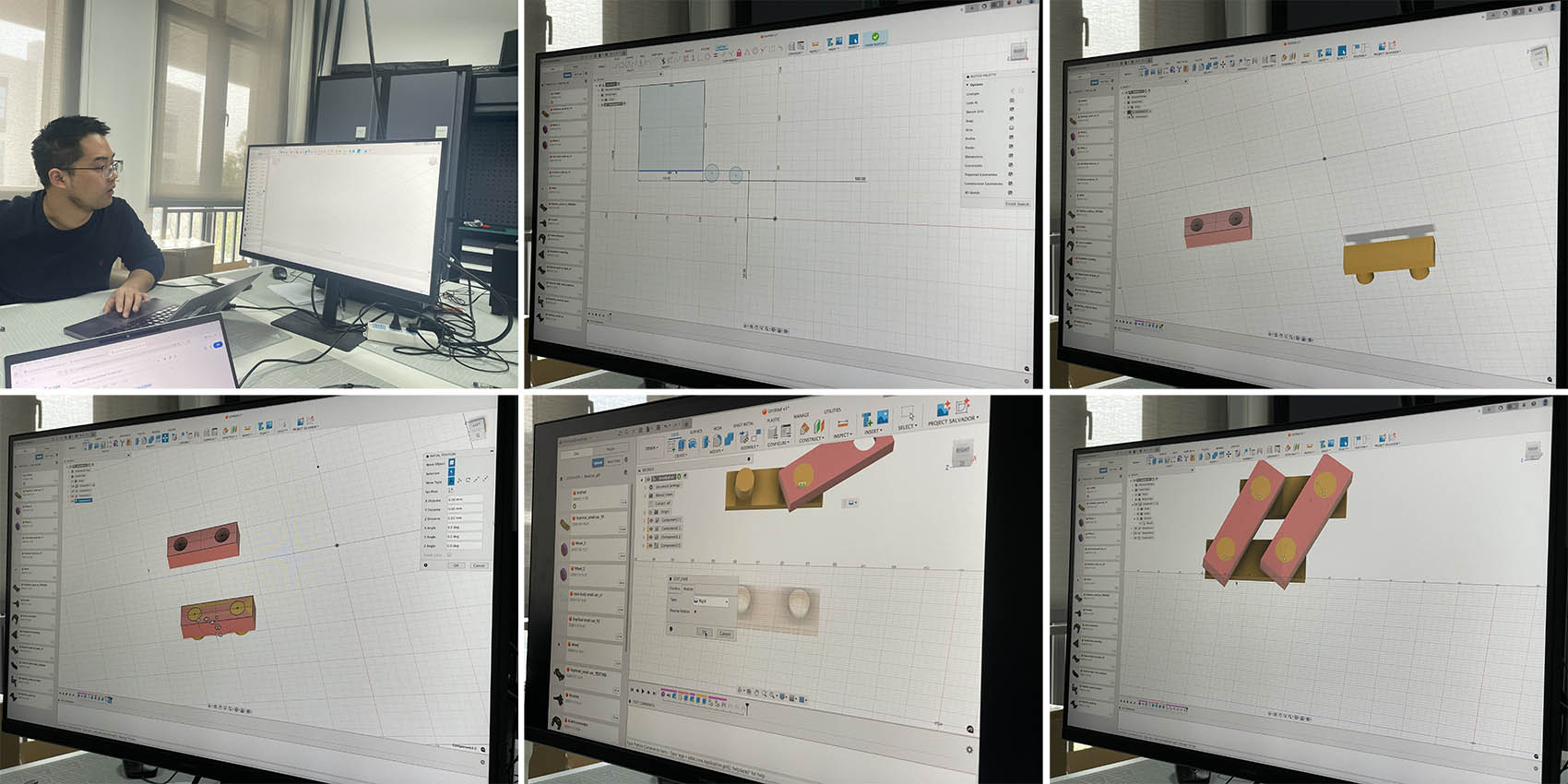
1. Autodesk Fusion 360
- Primary Use: Product design, rapid prototyping, and basic manufacturing (CAD/CAM/CAE).
- Modeling Style: Parametric, direct, and SubD (subdivision) modeling.
- Pricing & Accessibility: Subscription-based, around US$680/year. Free personal and discounted startup licenses are available.
- Best For: Makers, startups, and engineers who need to move from a sketch to a 3D printable or machinable part quickly without buying multiple expensive tools.
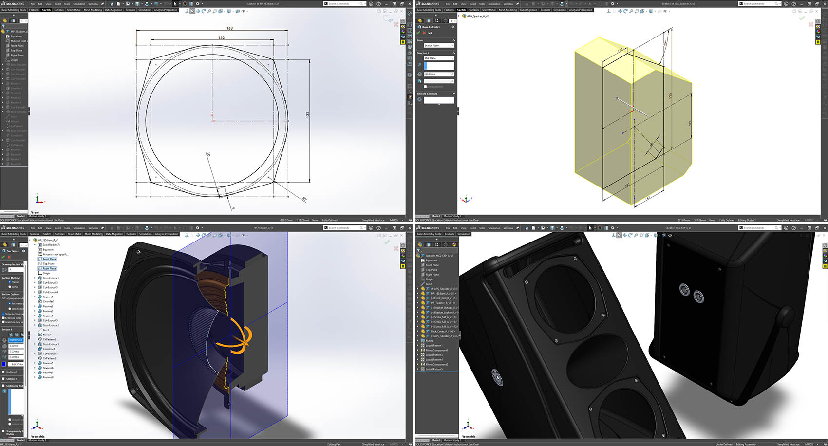
2. SolidWorks
- Primary Use: Mechanical engineering, heavy assemblies, and structural simulation.
- Modeling Style: History-based, parametric 3D solid modeling.
- Pricing & Accessibility: Quote-based system, typically running US$3,000 to US$5,000/year for professional subscriptions, though cheaper maker tiers exist.
- Best For: Industrial machinery, complex mechanical assemblies, and engineering firms that require strict revision control and deep physics-based simulations.
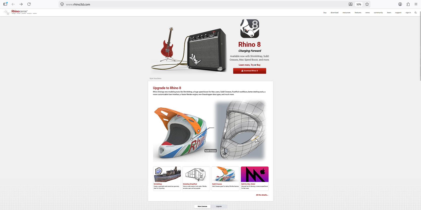
3. Rhino 3D
- Primary Use: Industrial design, jewelry, naval architecture, and organic shapes.
- Modeling Style: NURBS (Non-Uniform Rational B-Splines) and SubD modeling.
- Pricing & Accessibility: Perpetual license model, roughly US$995 to US$1,195 for a full commercial seat.
- Best For: Unrestricted freeform modeling. It is highly prized for its vast plugin ecosystem and Grasshopper (visual programming) integration, which allows for complex, generative architecture and design.
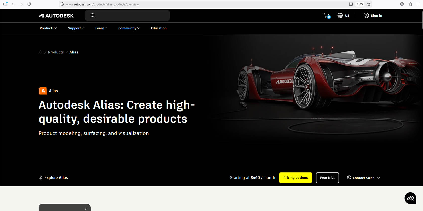
4. Autodesk Alias
- Primary Use: Transportation and automotive design, Class-A surfacing.
- Modeling Style: High-end freeform, mathematical curve creation, and Class-A surfacing.
- Pricing & Accessibility: High-end, quote-based Autodesk enterprise subscription, often exceeding US$5,000/year.
- Best For: Professional automotive exterior designers. It provides the high degree of mathematical precision and light reflection continuity required for physical car manufacturing.
► KEY STRENGHTS & WEAKNESSES ◄
| SOFTWARE | PRIMARY STRENGTH | WEAKNESS |
|---|---|---|
| Fusion 360 | Highly accessible; combines CAD, CAM, and cloud sharing in one interface. | Less capable at handling massive, highly complex assemblies compared to Solidworks. |
| Solidworks | Industry standard for mechanical design and standard drafting practices. | Steep learning curve, rigid workflows, and high long-term IT/licensing costs. |
| Rhino 3D | Uninhibited, rapid freeform surface creation at an affordable perpetual cost. | Poor native tools for traditional parametric engineering and history-driven assemblies. |
| Autodesk Alias | Flawless, production-ready Class-A automotive surfacing. | Extremely steep learning curve; cost is prohibitive for independent or general use. |
2D CAD Software
For the 2D CAD section, I will cover AutoCAD, Adobe Illustrator, and Affinity serve different core purposes. AutoCAD is a precise, parametric 2D/3D CAD tool for engineering and architecture. Illustrator is the industry-standard vector graphics suite for branding and marketing. Affinity is a nimble, budget-friendly vector/raster hybrid favored by independent designers and illustrators.
1. AutoCAD
- Primary Use Case & Core Philosophy: Designed strictly for measurable, mathematical drafting, scaling, and engineering layouts. It relies on exact dimensions, snapping to absolute coordinates, and industry-standard layers (architectural/MEP).
- Precision and Workflow: Requires precision first. Everything is drawn to scale using exact numerical values, coordinates, and units. File formats are generally proprietary .dwg or .dxf.
- Pricing & Accessibility: Operates on an ongoing subscription model. An annual Autodesk subscription is around US$2,310/year for full capabilities (though a stripped-down LT version is roughly half the cost).
- Learning Curve: Steep learning curve. Success requires mastering command-line inputs, object snaps, plotting scales, and layer management.
2. Adobe Illustrator
- Primary Use Case & Core Philosophy: Built for artistic creation, typography, and illustration. It focuses heavily on aesthetics, complex path building, brushes, and digital art layouts for print or web.
- Precision and Workflow: Highly precise for artistic work but not mathematical engineering. It uses Bézier curves and handles infinite scaling for branding, logos, and typography. It is the industry standard for sending vector files to print shops.
- Pricing & Accessibility: Exclusively subscription-based. Pricing starts at approximately ($20.99)–($22.99) per month depending on the annual commitment.
- Learning Curve: Steep learning curve due to an incredibly extensive set of menus, tools, and nested sub-panels.
3. Affinity by Canva
- Primary Use Case & Core Philosophy: A unified app with studios for vector design, photo editing, and desktop publishing in one file
- Precision and Workflow: Includes native Image Trace for raster-to-vector conversion and lets users switch between vector, raster, and layout work without app changes. It also supports cloud saving to Canva folders.
- Pricing & Accessibility: Free for core professional use, but a free Canva account is needed to activate it. Advanced AI features like Generative Fill and Background Removal require Canva Pro.
- Learning Curve: Moderately steep, since it combines three workflows in one interface, but the clean design and consistent tools make it easier to learn than Adobe’s separate apps.
► KEY STRENGHTS & WEAKNESSES
| SOFTWARE | PRIMARY STRENGTH | WEAKNESS |
|---|---|---|
| AutoCAD | Absolute millimeter precision, standard industrial DWG ecosystem, native command-line data entry, robust engineering toolsets. | Costly commercial subscription, exceptionally steep learning curve, non-existent creative graphic design tools. |
| Adobe Illustrator | Industry-standard vector ecosystem, absolute path editing precision, vast premium asset libraries, advanced typography. | Pricey ongoing subscription model, disconnected app ecosystem, cluttered and overwhelming legacy panels. |
| Affinity by Canva | Free to use core tools, unified raster/vector/layout workspaces, blazing fast engine speed, native Canva cloud sync. | Advanced generative AI restricted to paywall, occasional file conversion inaccuracies, non-existent Linux support. |
3D CAD Practice: SolidWorks
For the 3D CAD practice, I decided to use SolidWorks (SolidWorks Education Edition from my university) to model a mechanism. I will be using this model for the 3D printing practice of Week 5.
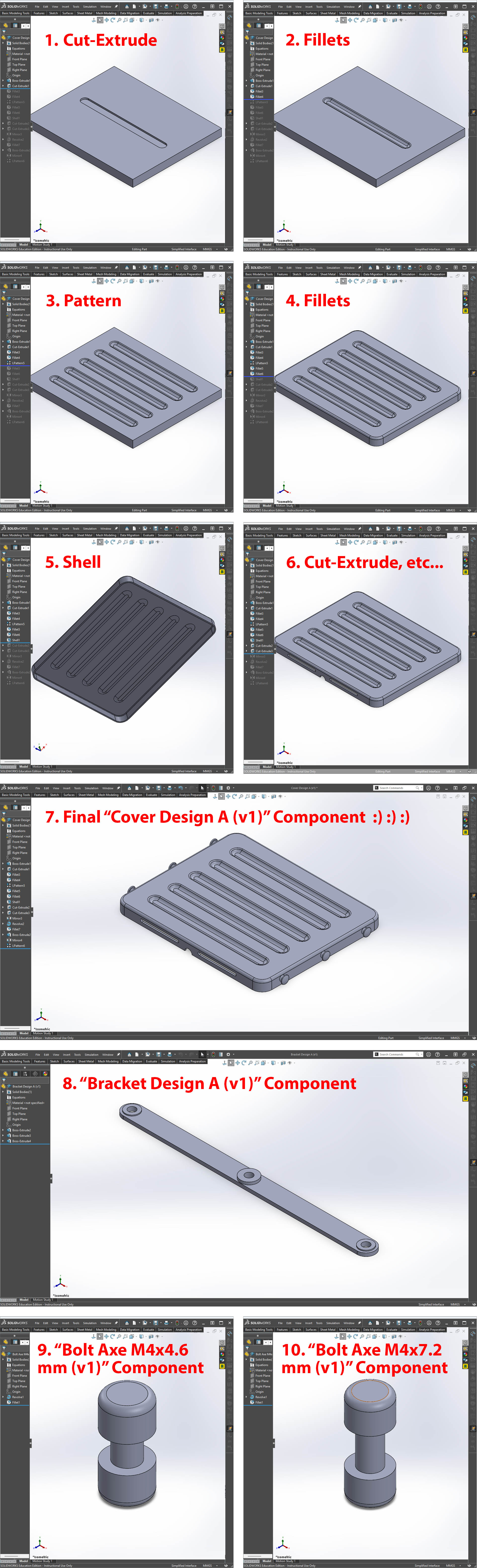
Part 1: PART FILE (a 3D representation of a single design component)
I created a 3D model in SolidWorks by starting a new part, drawing a 2D shape on a plane, adding dimensions, and turning it into a 3D feature.
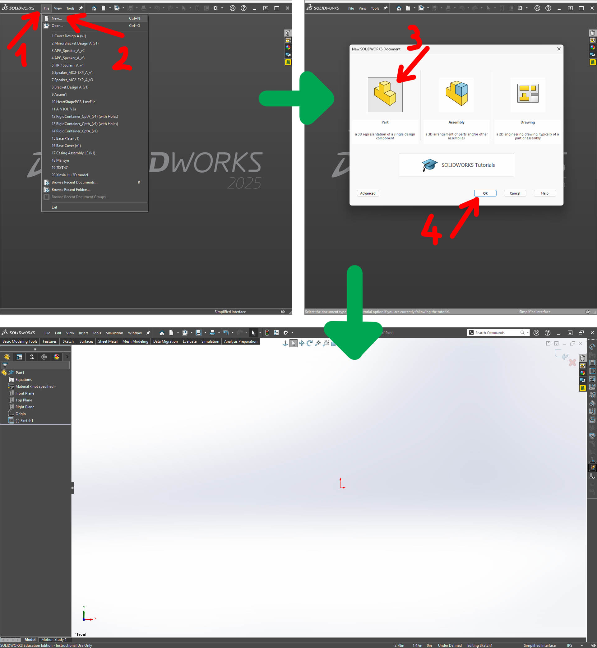
Step 1: Create a New Part File
Open SolidWorks. Click File > New (or press Ctrl + N). Select Part and click OK.
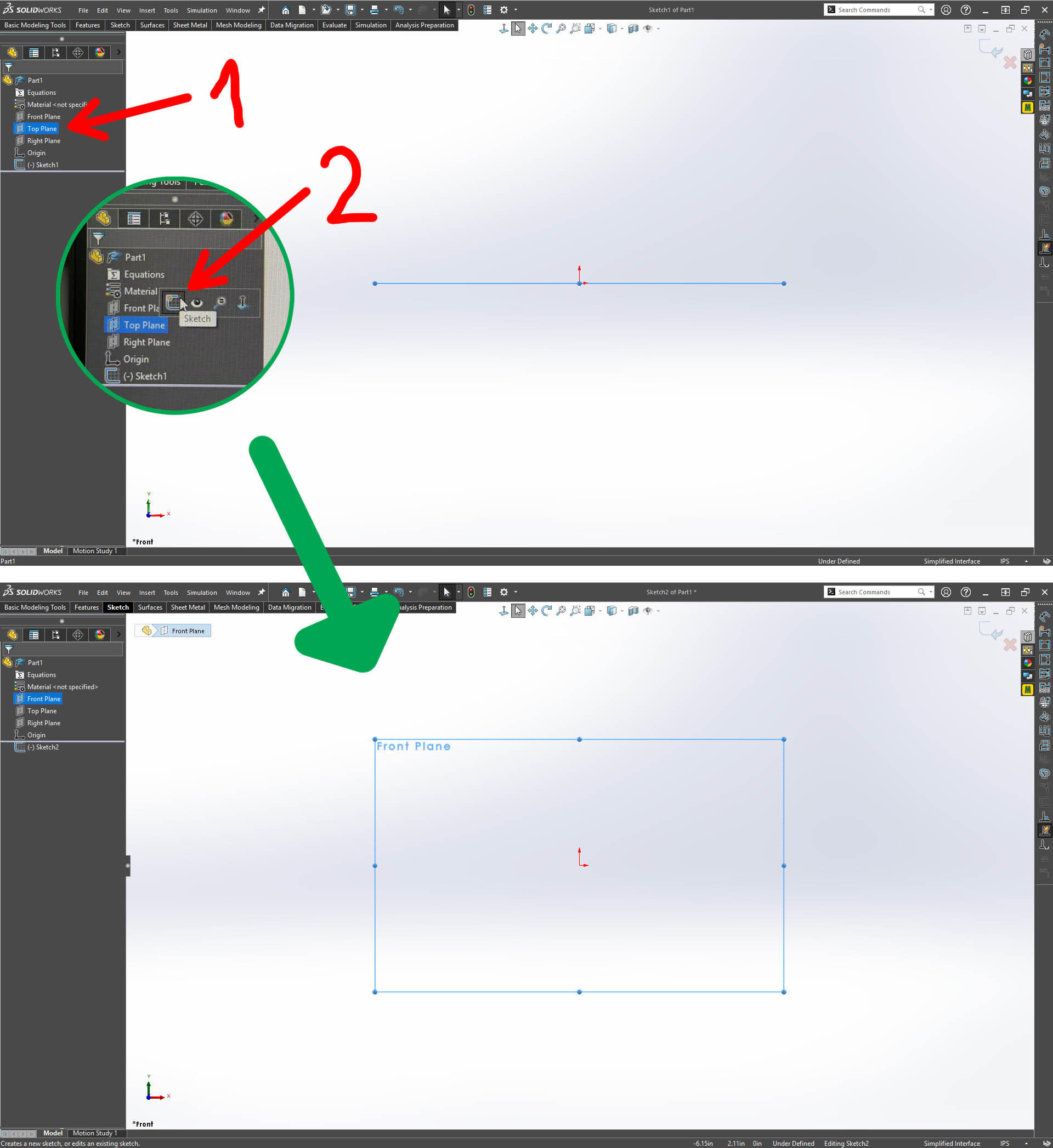
Step 2: Select a Reference Plane
Look at the left side of the screen at the Design Tree. Click on the Top Plane (Front Plane or Right Plane if more appropriate for you). Then, click the Sketch icon that pops up to start your 2D drawing.
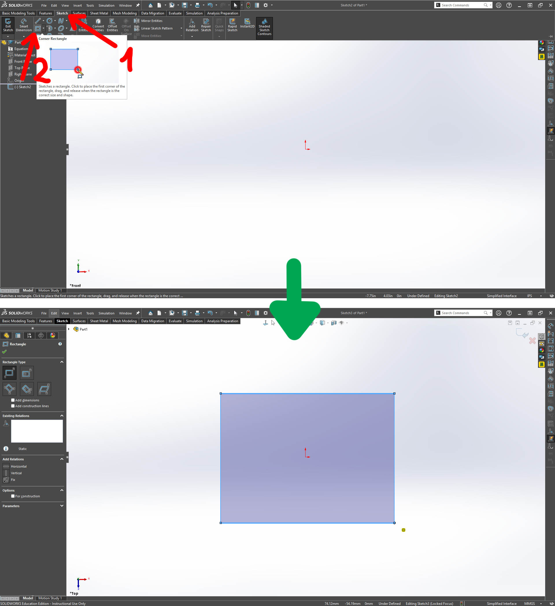
Step 3: Draw Your 2D Sketch
Pick the Rectangle drawing tool from the Sketch tab (or any other drawing tool like Line, Circle, or any other if more appropriate for you). Draw a rectangle shape around the Origin point dot.
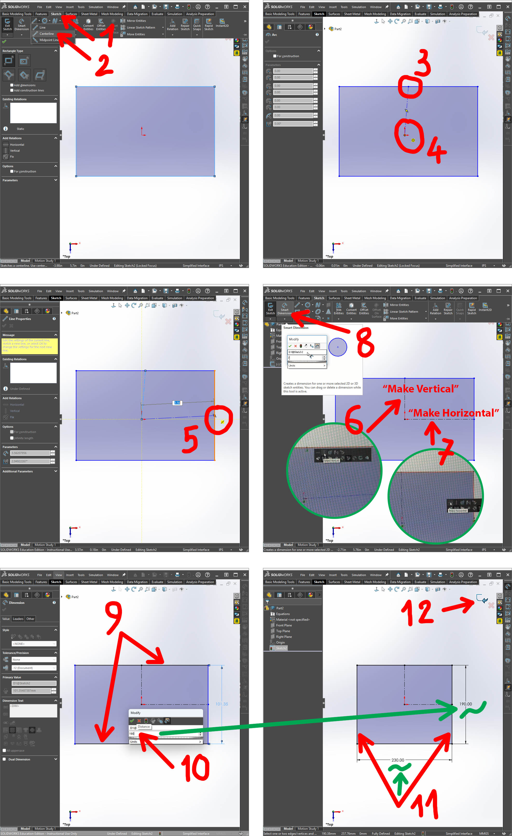
Step 4: Add Relations and Dimensions
Add vertical and horizontal centerlines (as displayed on the image below) so your sketch stays locked in space. Select the lines while holding the Control key to add relations like Horizontal, Vertical. Click Smart Dimension on the toolbar to set exact sizes for the rectangle. The colour of the whole sketch turns black once fully defined. Click the blue arrow at the top right of the screen to validate the sketch. Click File > Save.
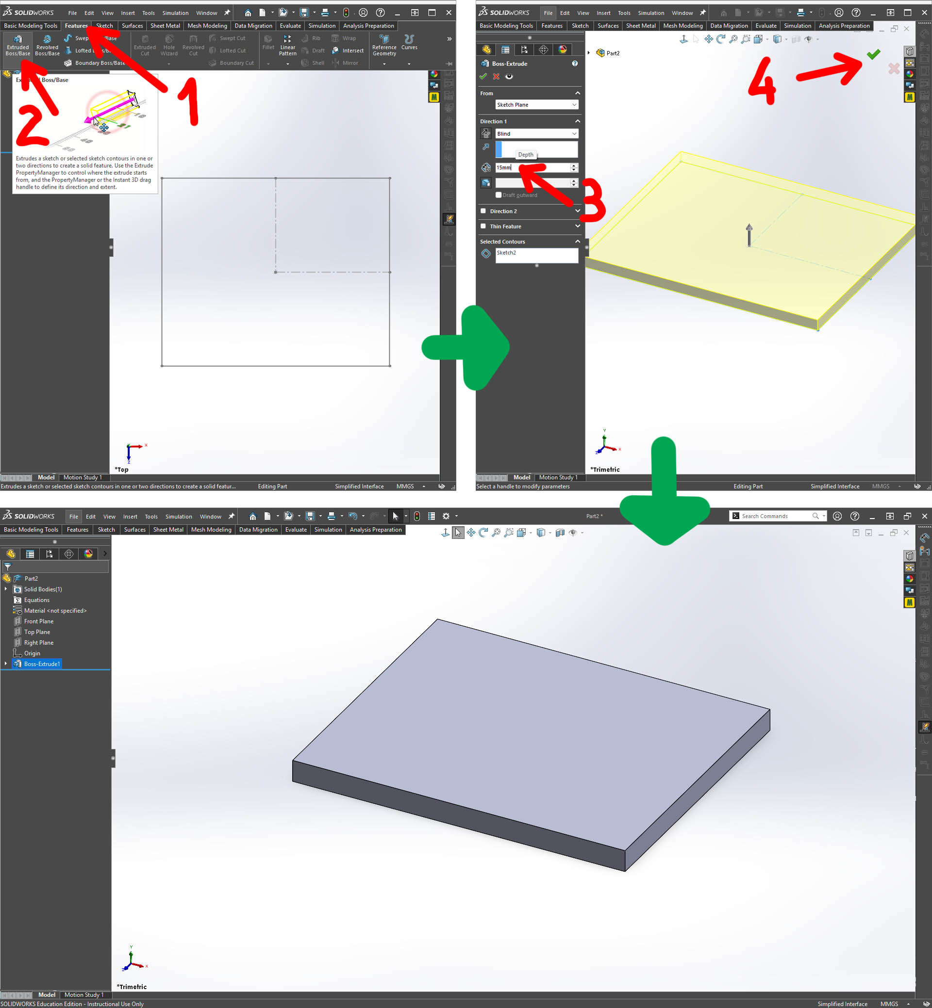
Step 5: Create a 3D Feature
Go to the Features tab at the top of the screen. Click Extruded Boss/Base to pull the flat drawing into a 3D block. Type the desired depth value (15mm) and click the green checkmark to finish.
Step 6: Add Details and Save
Use extra tools like Extruded Cut to make holes, Fillet to round sharp edges or any other Feature tools to complete the design. Click File > Save to store this source file on my laptop (SW file in the REFERENCE FILES section below).
Part 2: ASSEMBLY FILE (a 3D arrangement of parts and/or other assemblies)
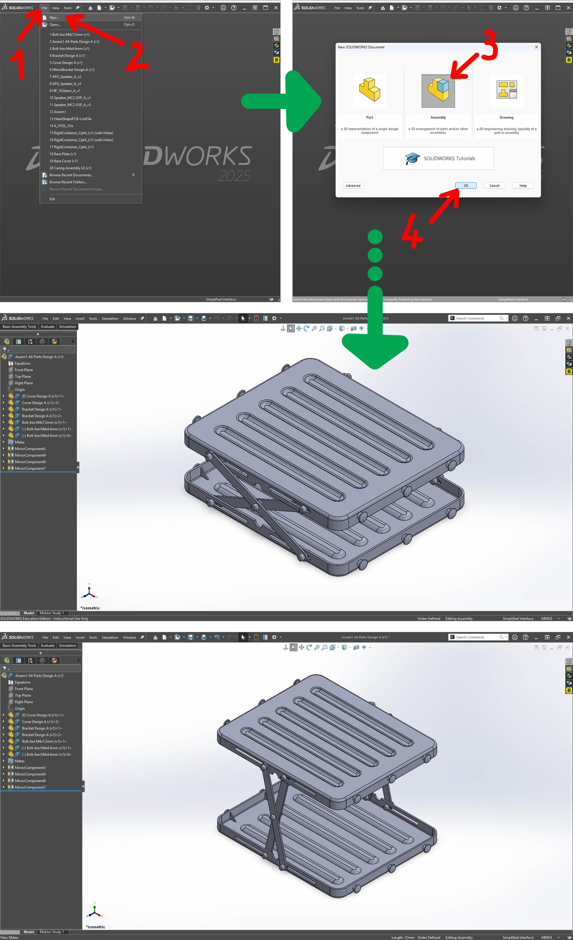
After having modelised all the components, I created an Assembly File in SolidWorks. I first imported the Base Component (Cover Design A (v1)) which becomes fixed and cannot move. I inserted the other components one by one while applying Assembly Mates. Then, I tested the Mechanism by clicking and draging the moving parts to visually check the physical range of motion, and made adjustements on some part's design features and dimensions when necessary. The file was saved as "Assem1 All-Parts Design A (v1).SLDASM" (see the REFERENCE FILES section below).
Part 3: VIDEO ANIMATION of my Assembly
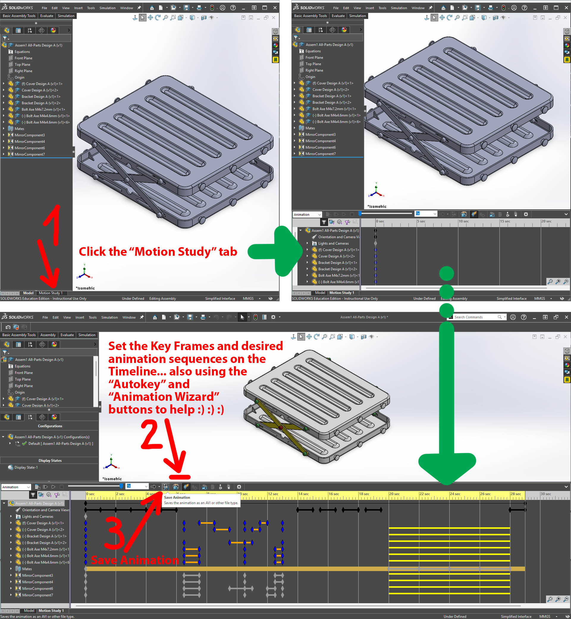
Once my SolidWorks components and assembly have been fully refined, I decided to create a video animation to visually demonstrate the system and its mechanism (and also practice "video compression", one of this week's requirements - See "Image & Video Compression" section below)
Compressed Video:
2D CAD Practice: Adobe Illustrator
For the 2D CAD practice, I decided to use Adobe Illustrator (using the license of my university) to create a test artwork/file for Week 3, Computer Controlled Cutting, to test the clearance of our laser cutting cutting machine.
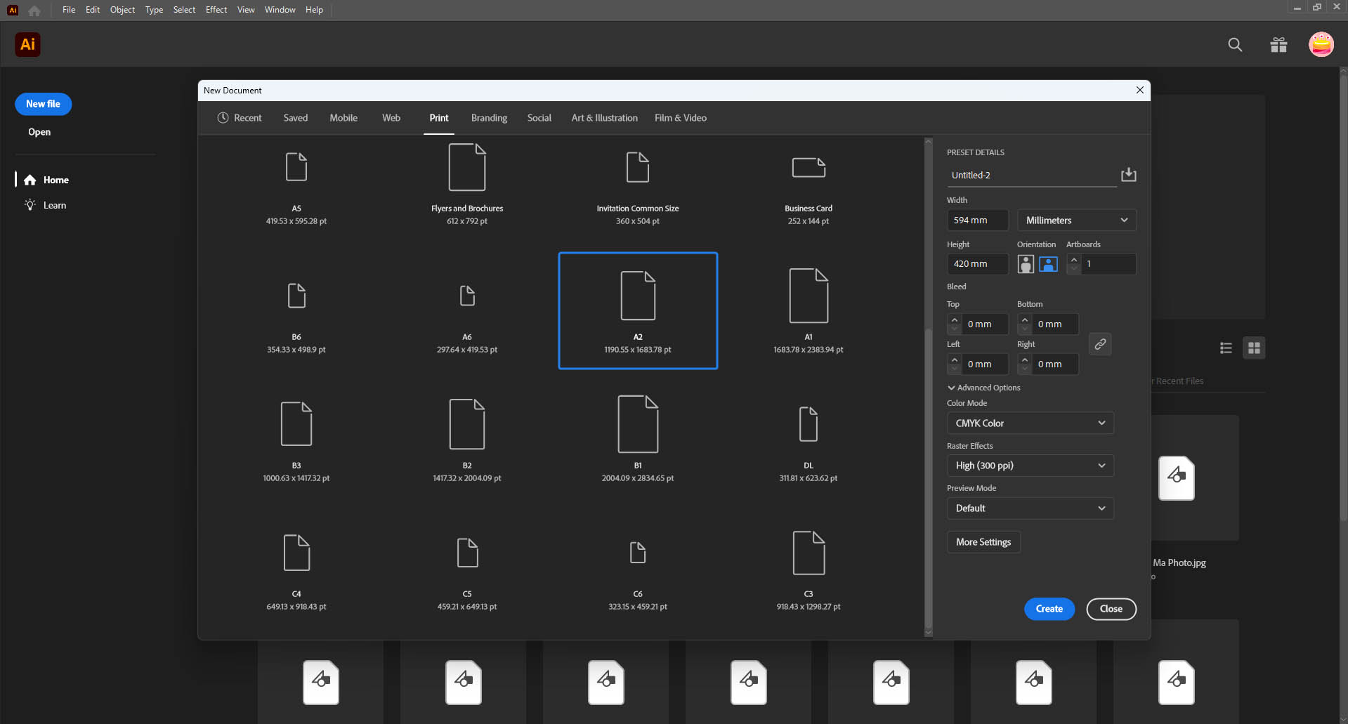
Step 1: Create a "New File"
- Settings: A2 size, landscape, millimeters (mm)
Step 2: Create the base shape
- Select the Rectangle tool, and create a square of 50x50mm
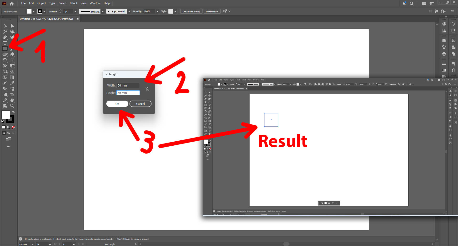
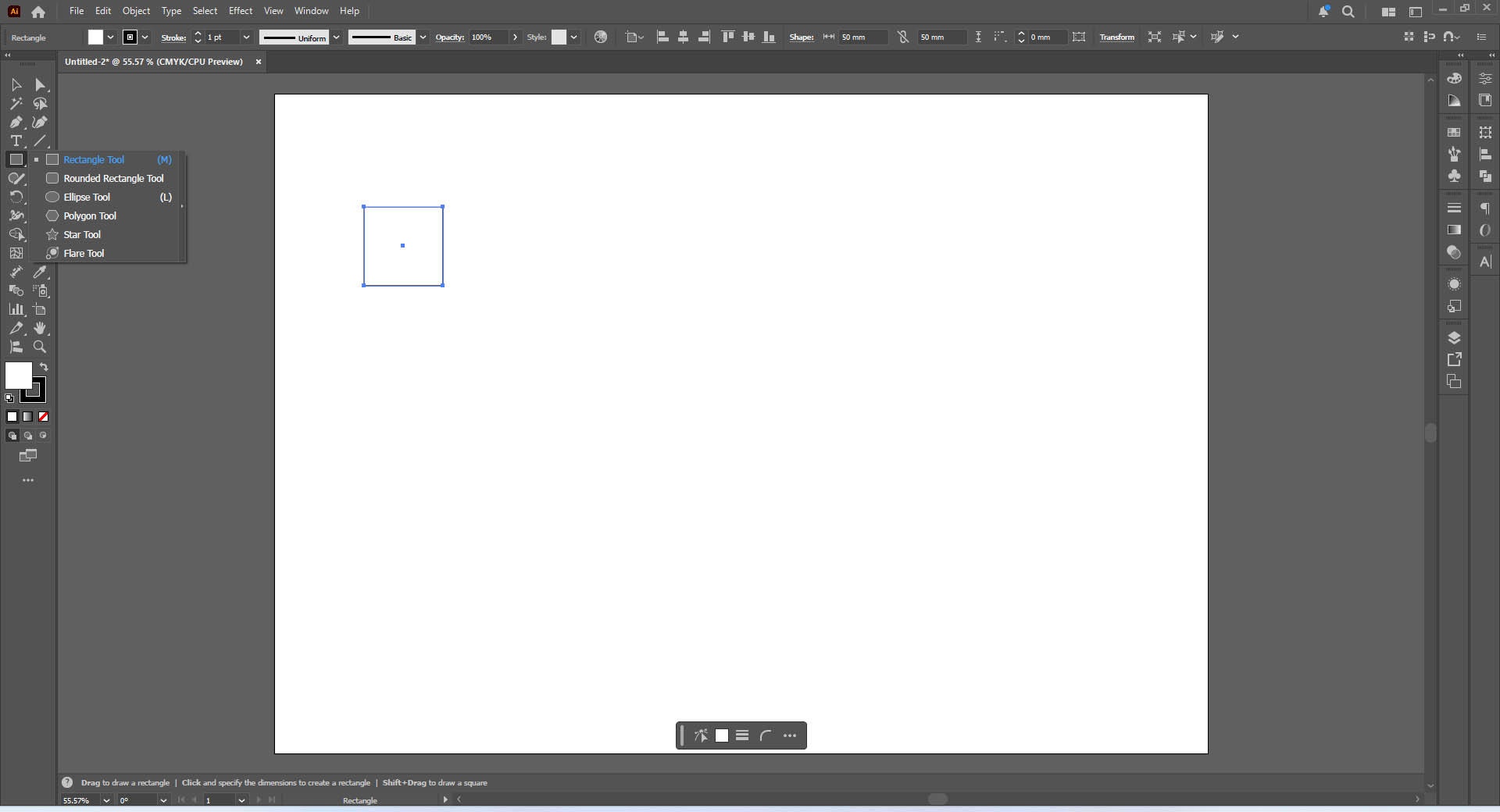
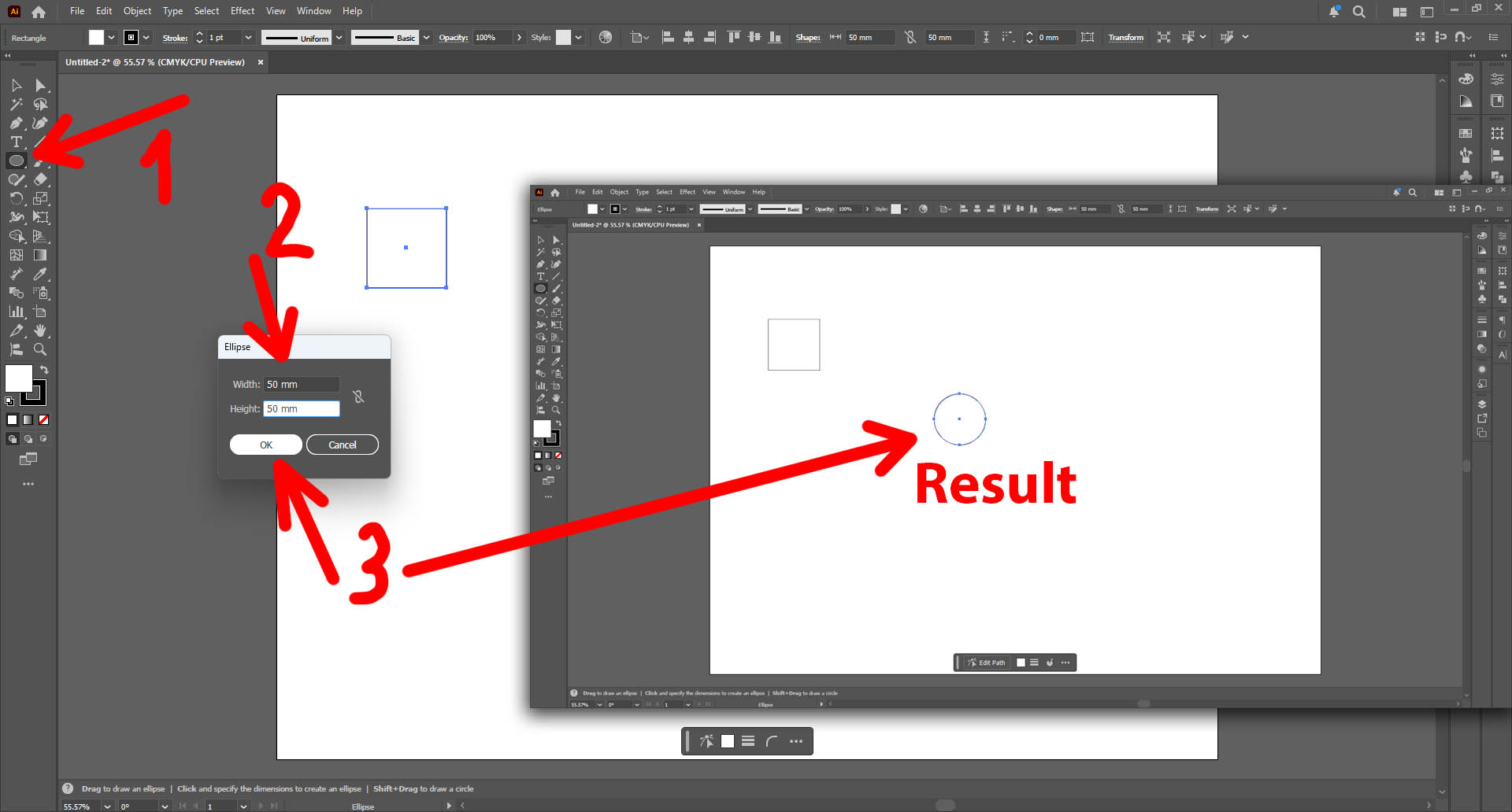
- Select the Elipse tool, and create a circle of 50mm diameter (50x50mm)
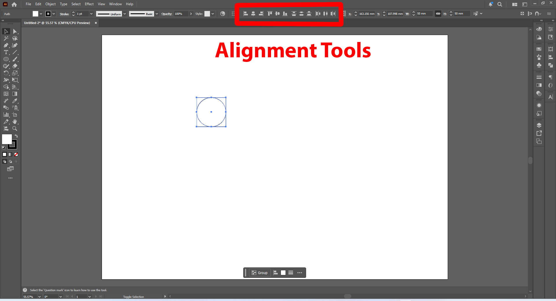
- Align the square with the circle using the Alignment Tools (vertically and horizontally)
- Use the Pathfinder Tools to "Divide" the geometries
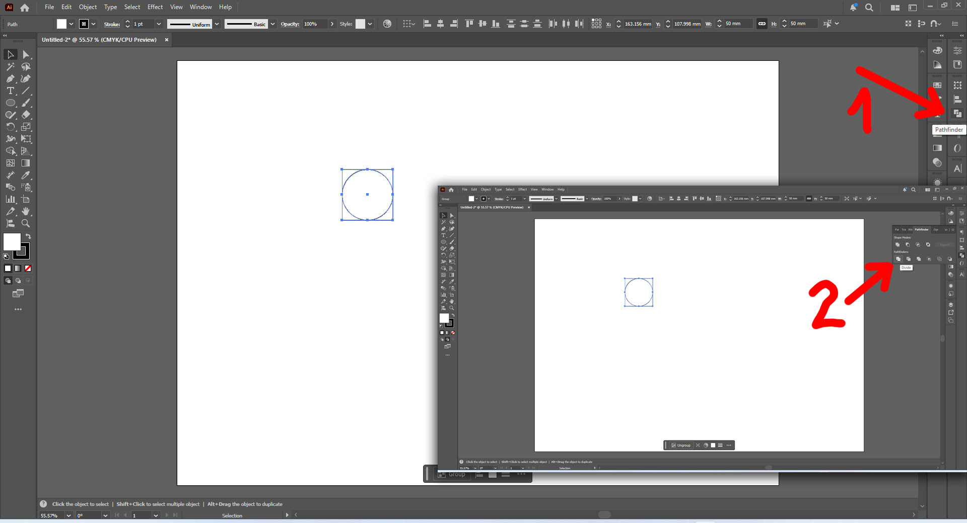
- Then, delete the unwanted two corners elements
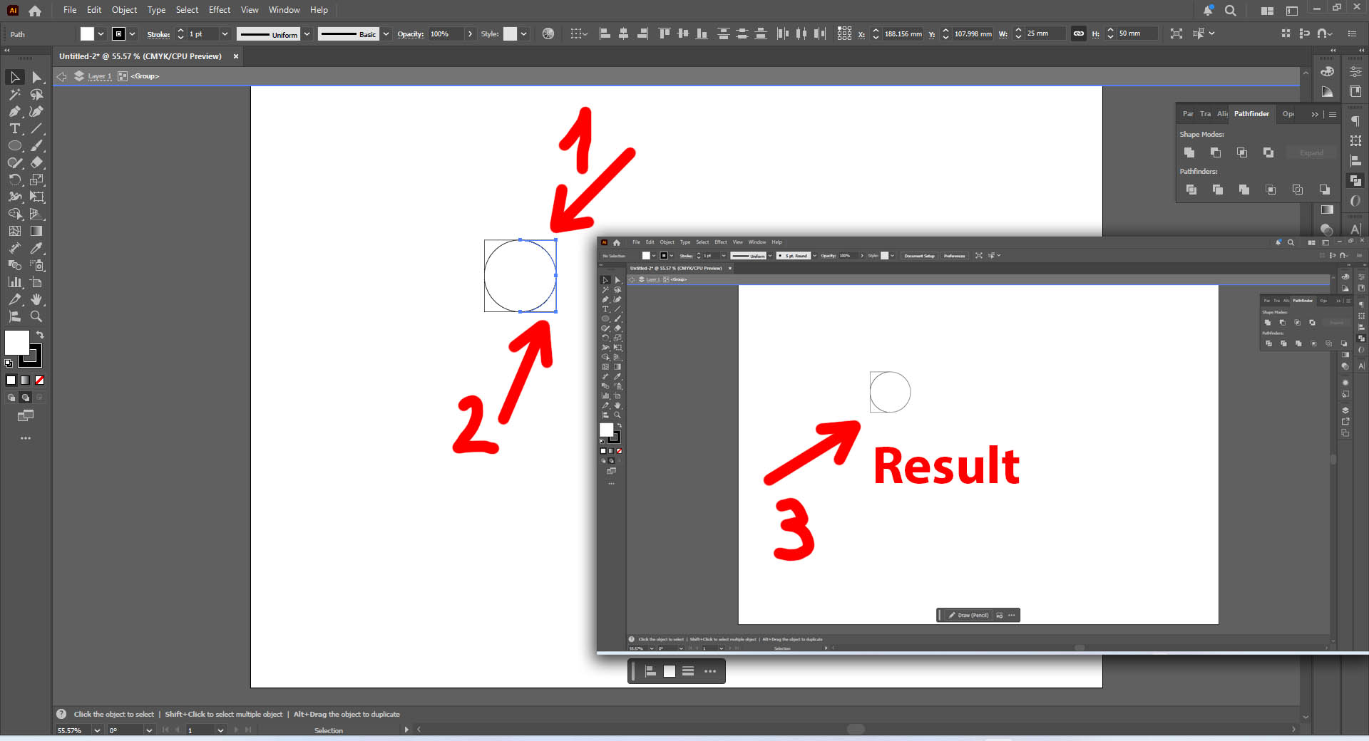
- Use the Pathfinder Tools to "Combine" the three elements left to obtain the final desired base shape/path
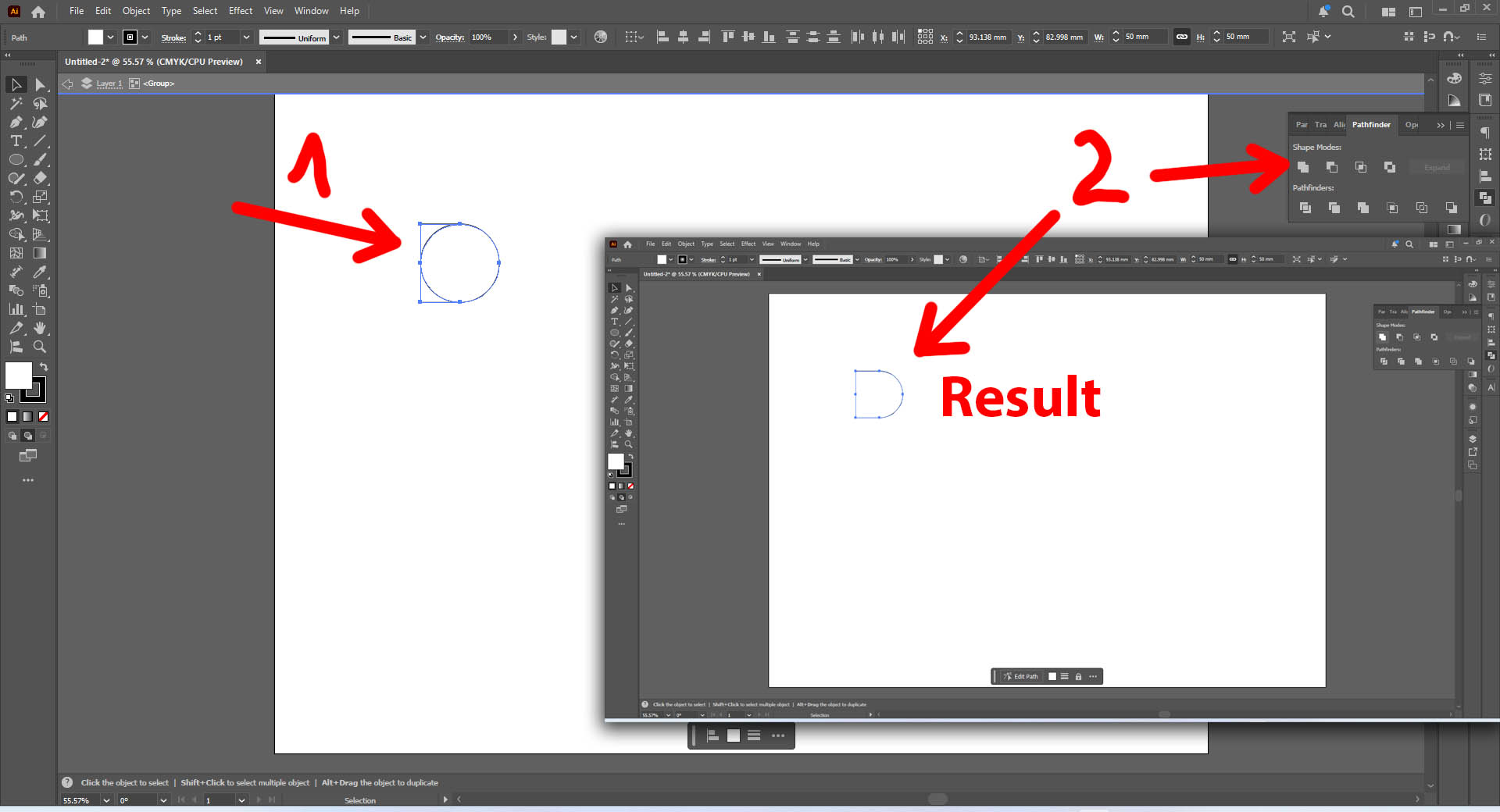
Step 3: Offset the base shape/path 4 times to obtain the final base artwork
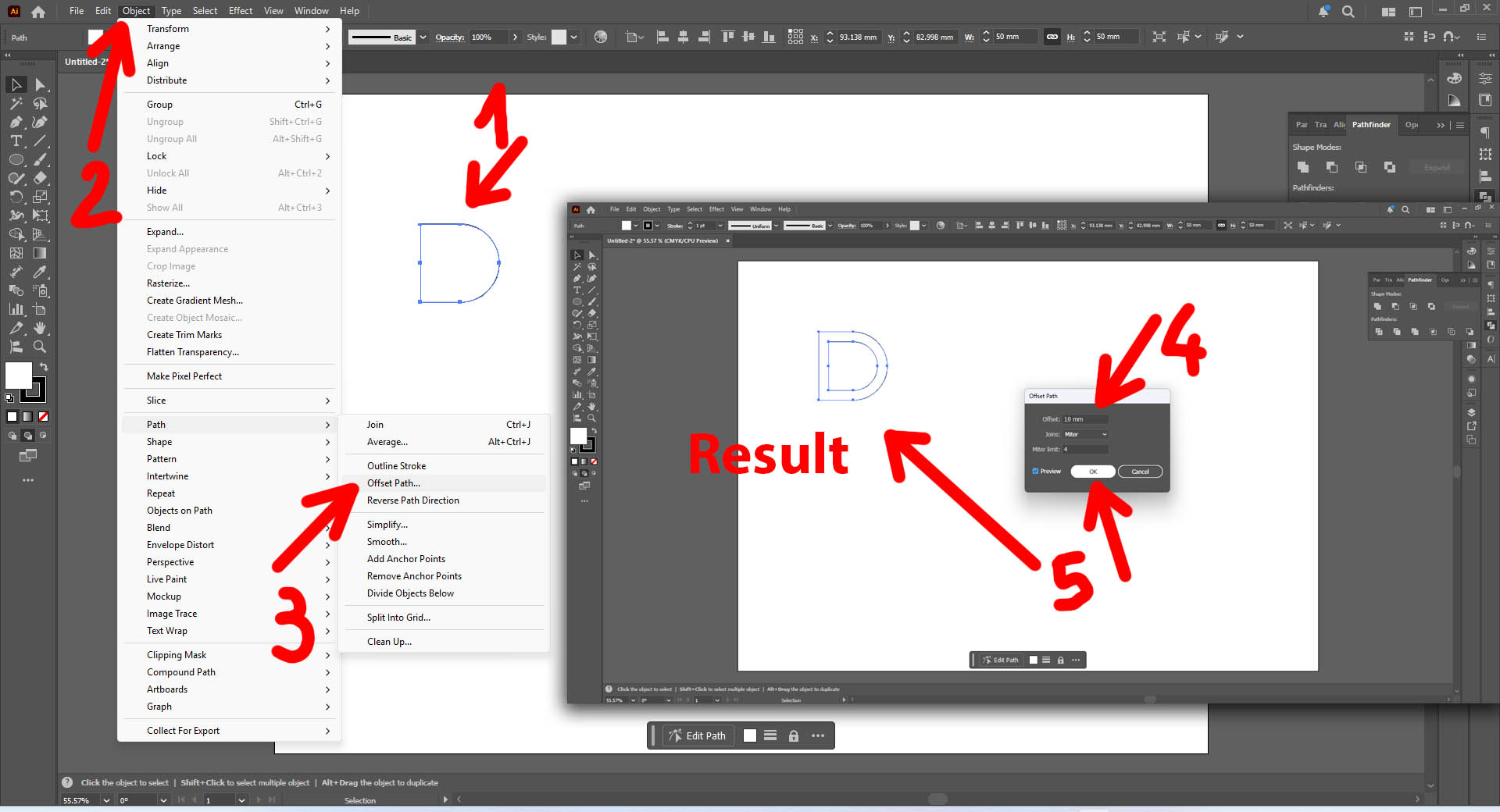
- Repeat the above actions (1/2/3/4/5) three times to obtain the following...
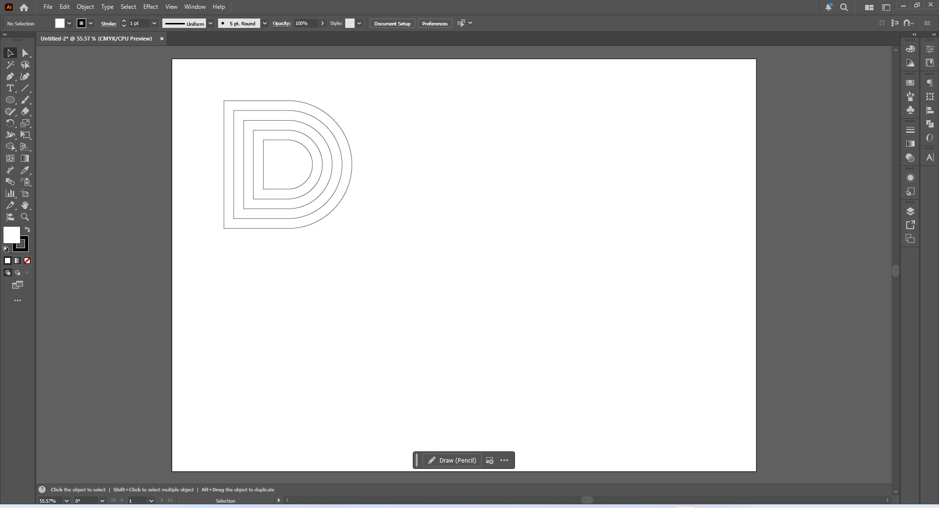
Step 4: Duplicate the base artwork to obtain the final complete test artwork
- Object > Move > (set distance) > Copy
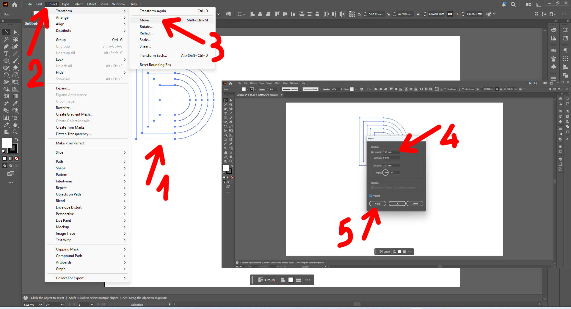
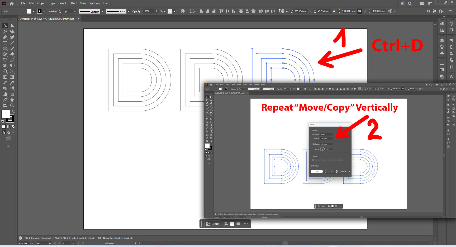
- Ctrl+D to repeat previous action, and reapeat Object > Move > (set distance) > Copy to duplicate vertically
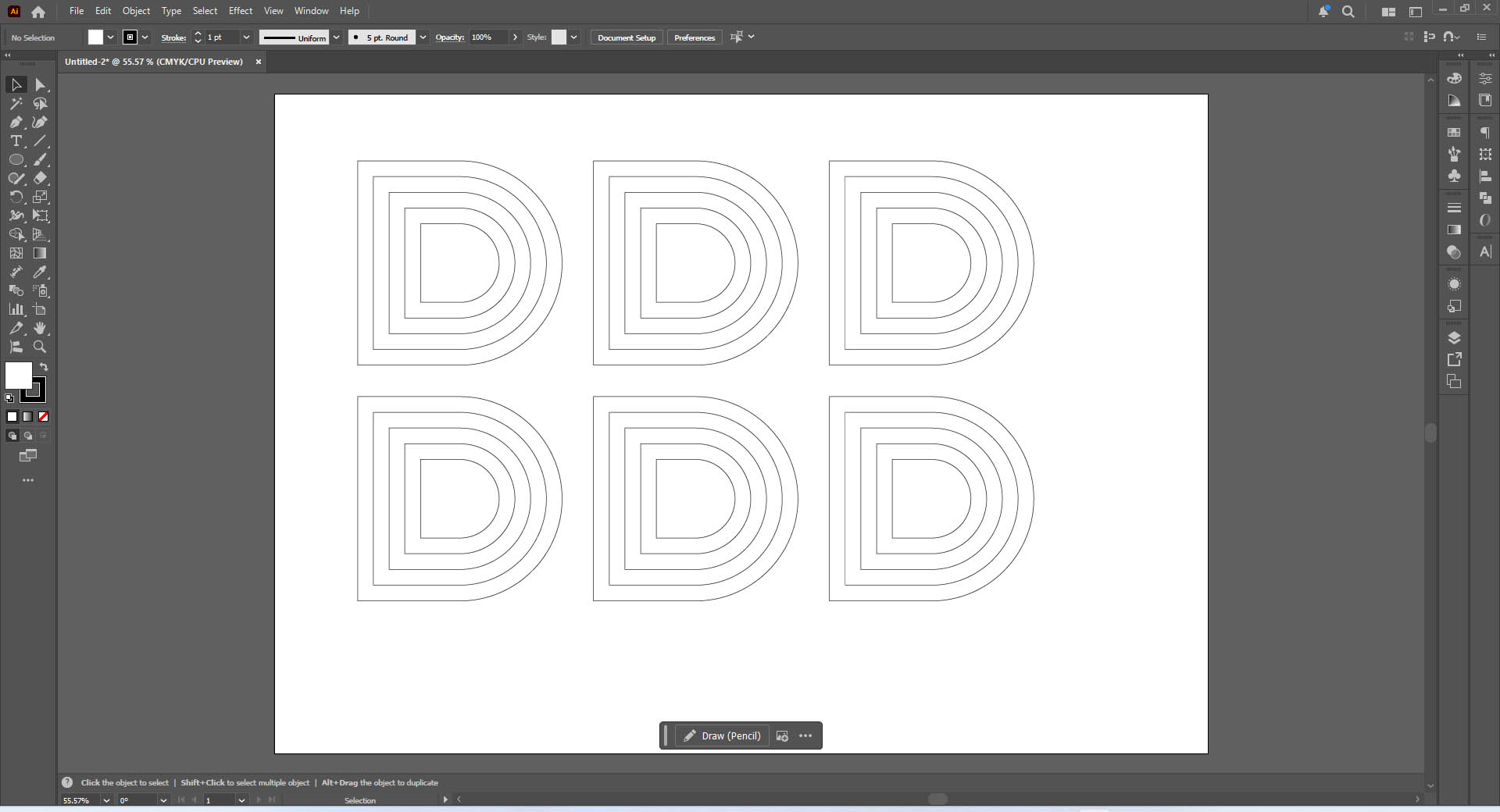
- Final Result:
- Save the file in AI format, and then export it in DXF format (as shown below) for full compatibility with the laser cutting machine software
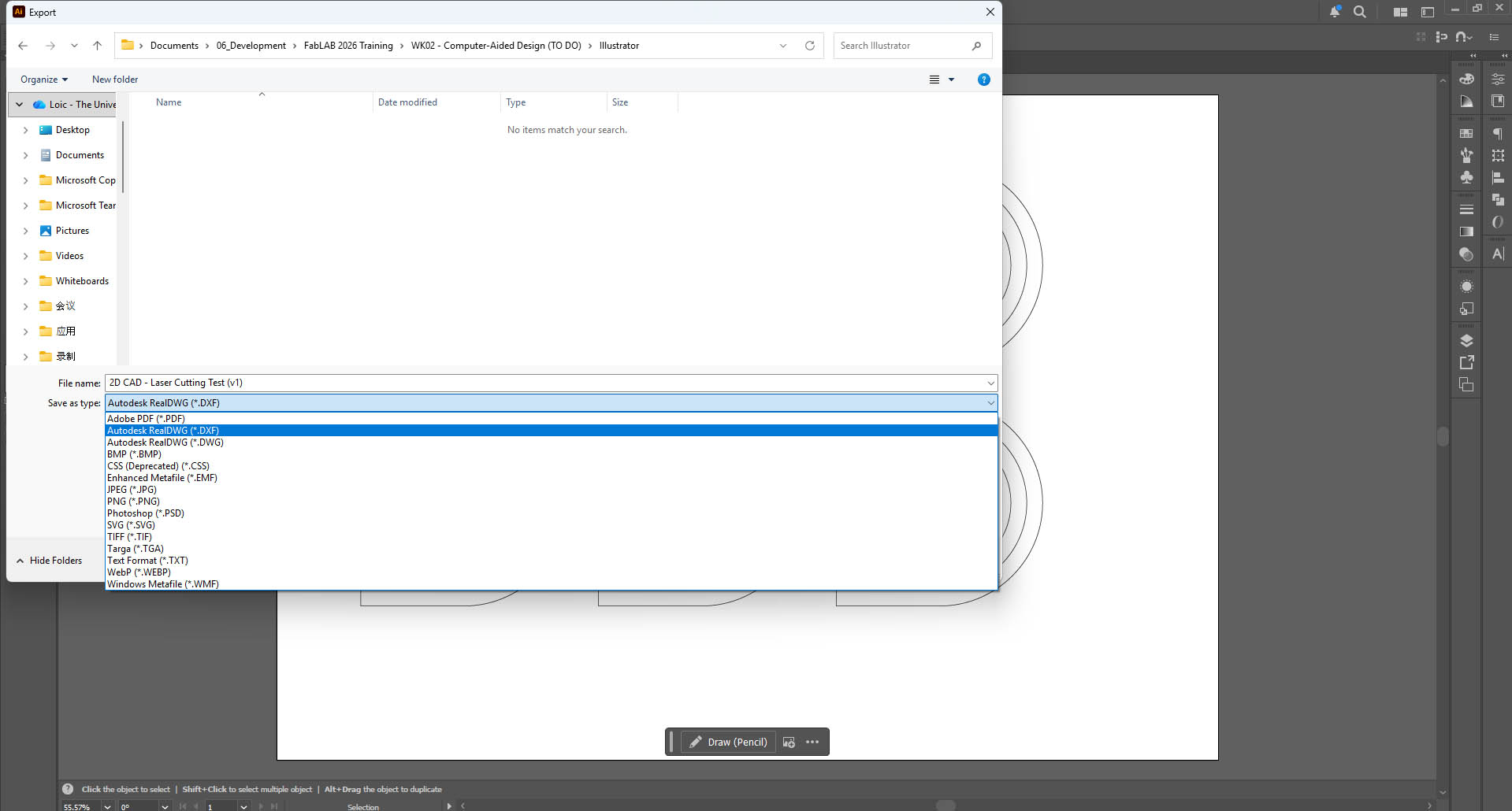
Image & Video Compression
Part 1: Image Compression
For the image compression, I have used Adobe Photoshop (part of the Adobe Cloud ecosystem), the industry-standard raster graphics editor used globally by photographers, designers, and digital artists to create, edit, and manipulate pixel-based images.
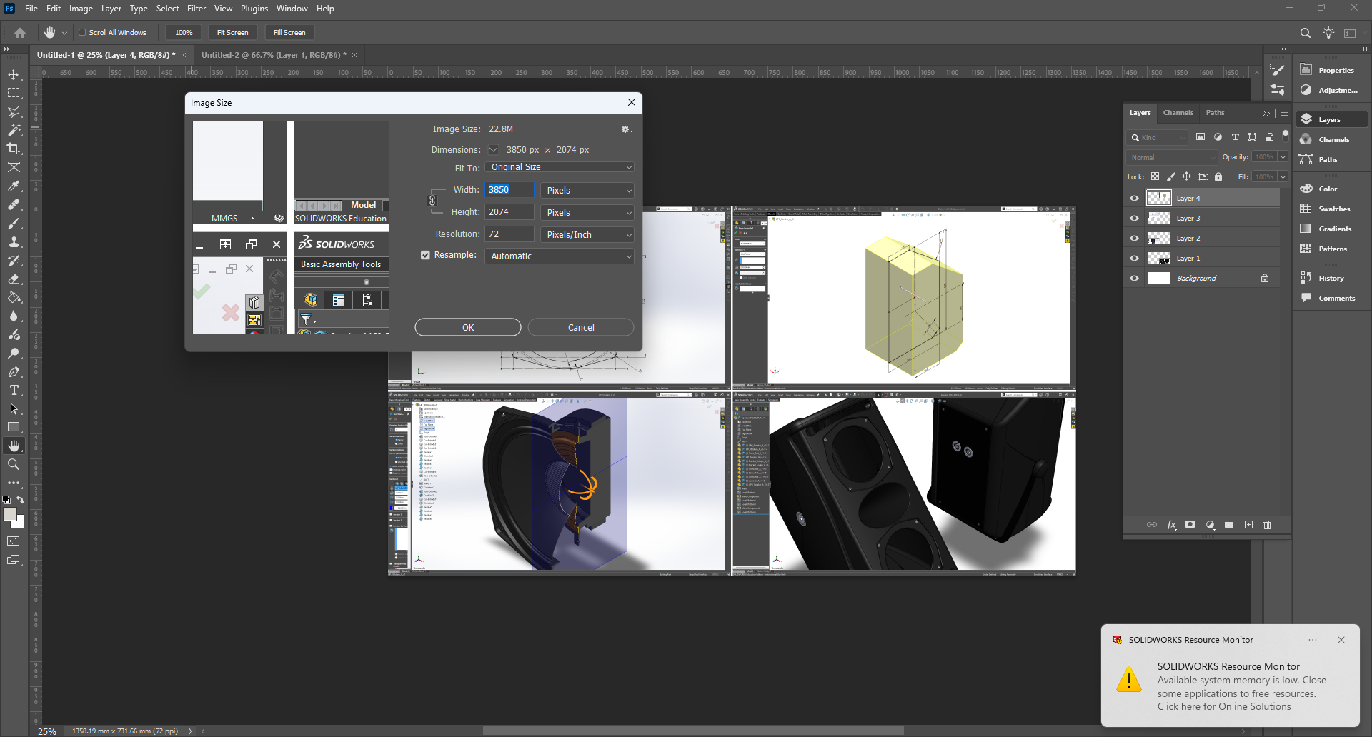
- Step 1: Image > Image Size
(original image size is 22.8MB, 3850x2074 Pixels, @ 72 Pixels/Inch)
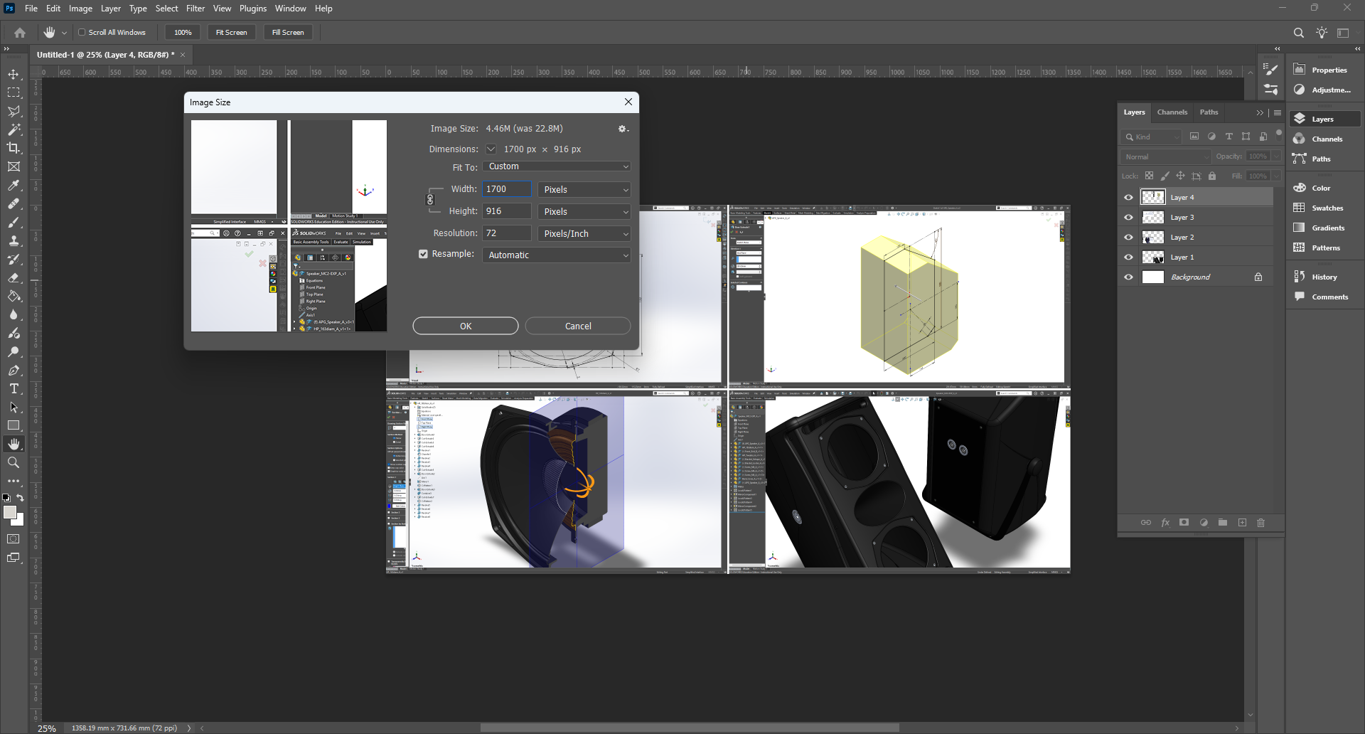
- Step 2: Set 1700x916 Pixels
(with "lock proportion" icon active, and "Resample" ticked - the image size is estimated at 4.46MB now instead of 22.8MB originally)
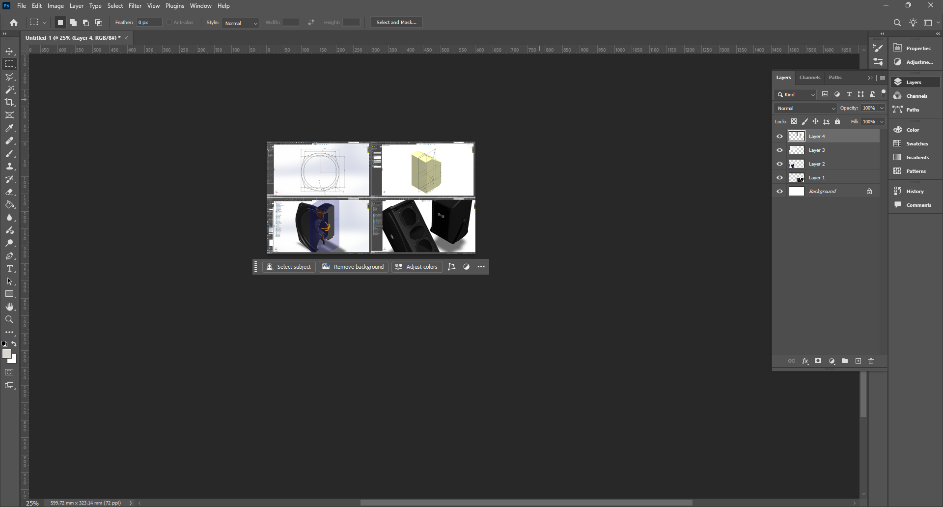
- Step 3: Click "OK"
(We can see that the image size has reduced on the display)
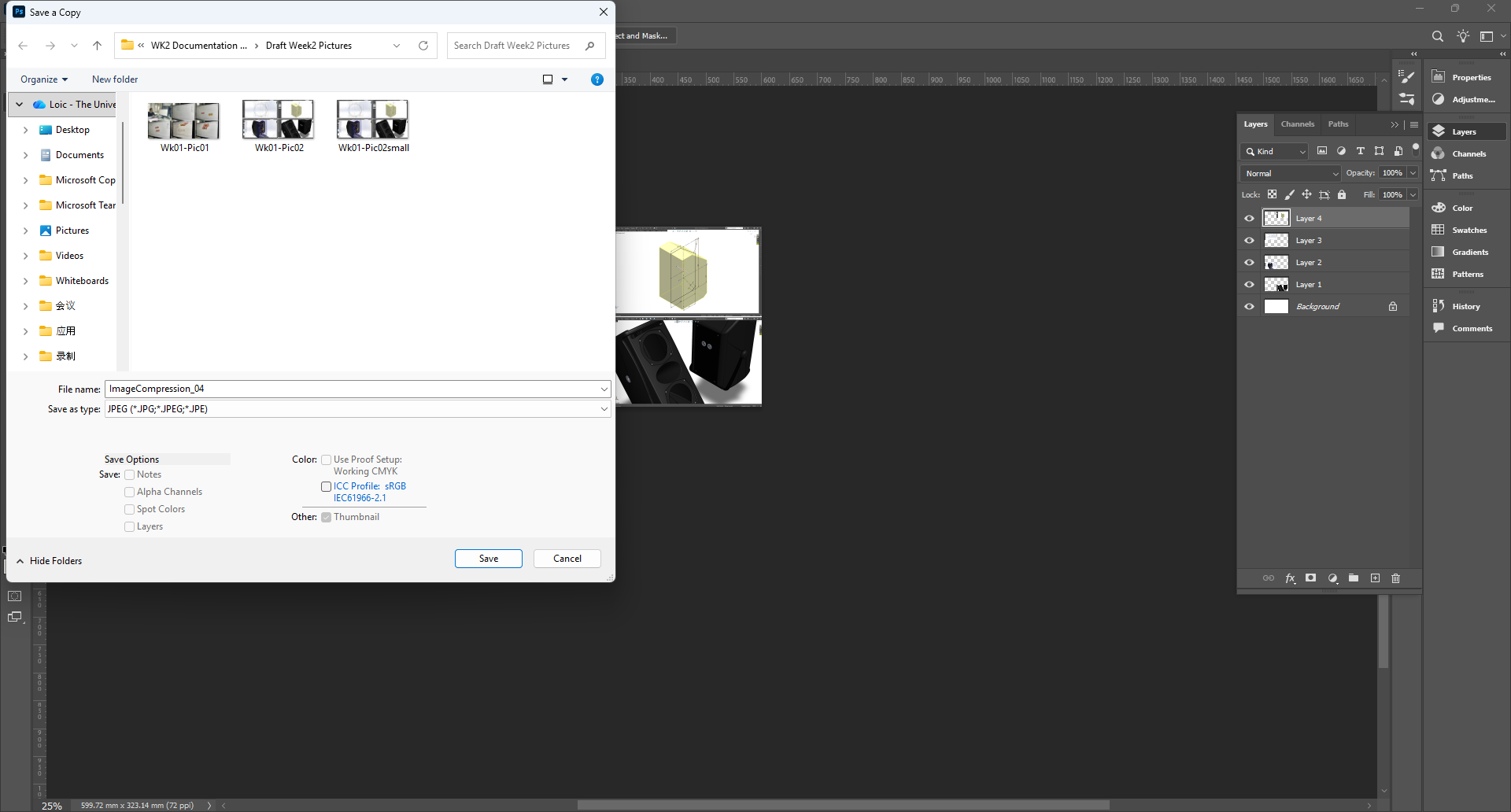
- Step 4: File > Save As
In "Save as type", Select "JPG" then click "Save".
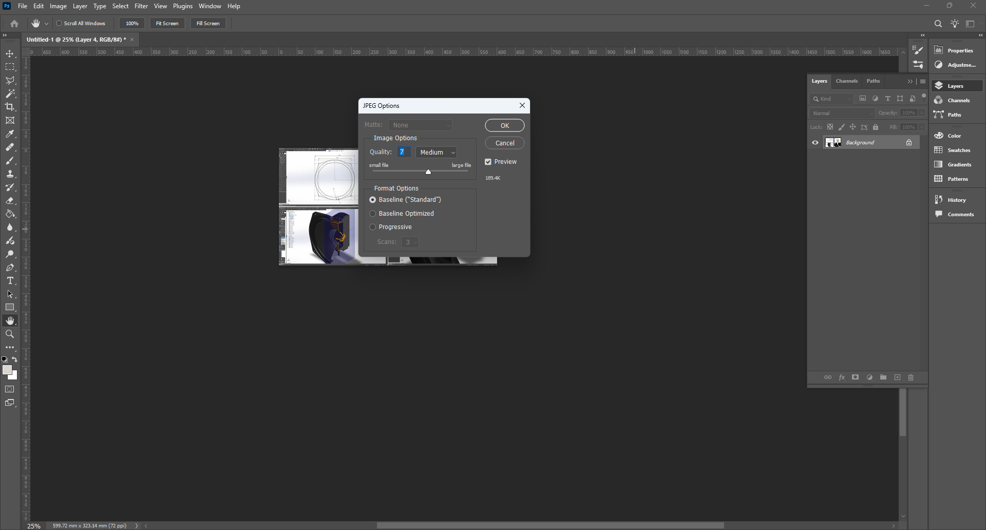
- Step 5: Set the JPEG Options as follow: Quality = 7 (Medium); Format Options = Baseline ("Standard"); the new compressed image is estimated to be 189.4KB. Click "OK".
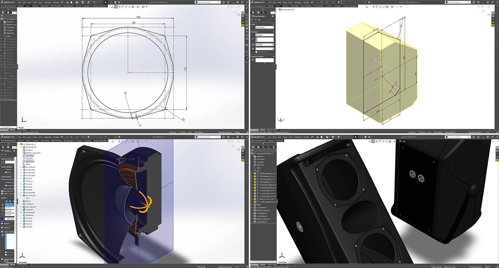
- This is the final compressed image, it is 186KB in JPG format (instead of 22.8MB originally)... the quality is still very good on screen 😃 😃 😃
Part 2: Video Compression
For the video compression, I decided to use HandBrake, a free, open-source video converter and transcoder used to convert digital video files from nearly any format into modern, widely supported codecs like MP4 or MKV.
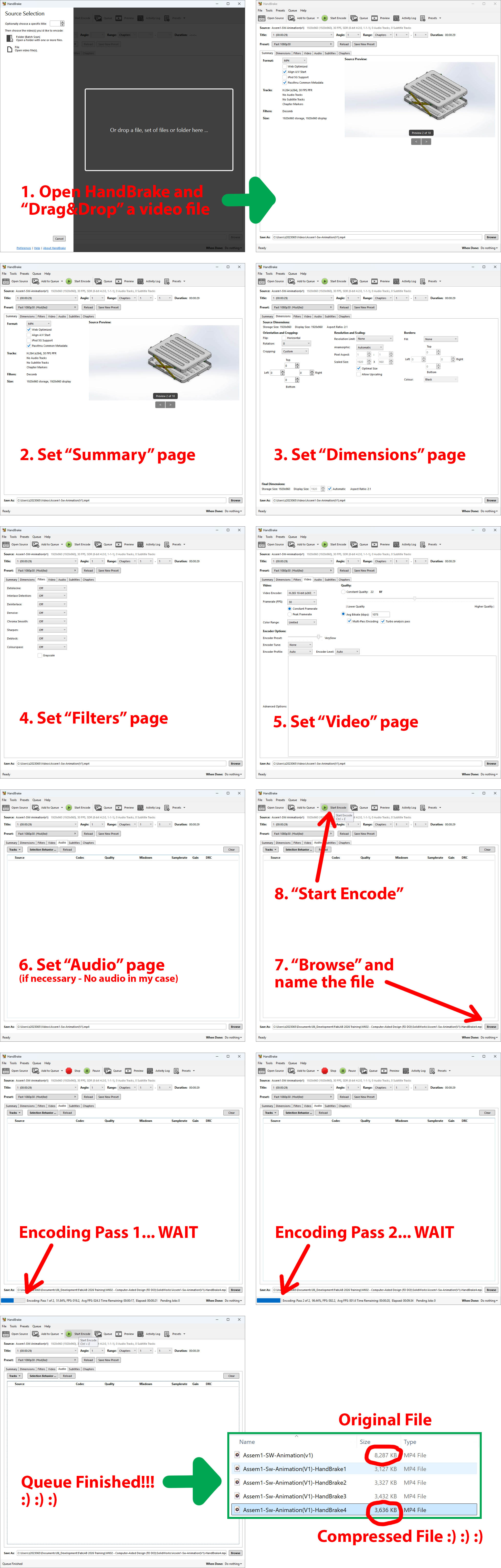
The original video file of my SolidWorks assembly is 29 seconds long, 1920x960p, 30fps, 8.1MB. Using the settings displayed in the below screenshots, I managed to reduce the size of the video to 3.54MB with HandBrake.
I used AI to guide/advise me on the right settings. At first, the quality of the compressed video was too low for my taste, but after two attempts, I managed to reach the expected video quality and smaller size.
REFERENCE FILES
SolidWorks Files
- Cover Design A (v1).SLDPRT
- Bracket Design A (v1).SLDPRT
- Bolt Axe M4x4.6mm (v1).SLDPRT
- Bolt Axe M4x7.2mm (v1).SLDPRT
- Assem1 All-Parts Design A (v1).SLDASM