Appearance
WEEK 15 – Interface and Application Programming
Assignments
Group Assignment
- Compare as many tool options as possible
Individual Assignment
- Write an application that interfaces a user with an input &/or output device that you made
Group Work
Our group work is accessible HERE (add the link)
Individual Work
Content Overview:
Arduino Cloud Platform Configuration
- Account Registration and Login
- Register and connect a Device
- Testing the Dashboard with Arduino UNO R4 Wi-Fi
"Test ONE" with Arduino Cloud + my PCB board with Xiao ESP32-S3 + Step Motor + Obstacle Sensor
- Create New Project
- Define my Variables
- Device Registration and Set-up (Xiao ESP32-S3)
- Data Visualisation: Dashboard
- Code Implementation and Testing (Failure)
"Test TWO" with Processing + my PCB board with Xiao ESP32-S3 + Obstacle Sensor
- Electronic Hardware Setup
- Data Visualisation and Testing
- Code Implementation
Arduino Cloud Platform Configuration
1. Account Registration and Login
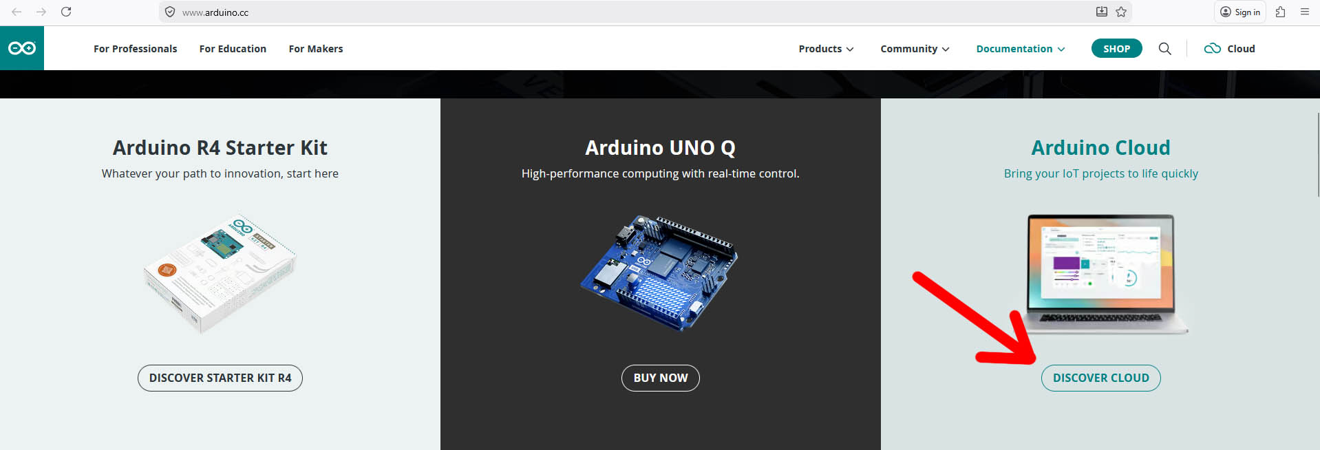
Visit the official website of Arduino Cloud and register an account. I create my account using my Google ID.
Click "Discover Cloud"
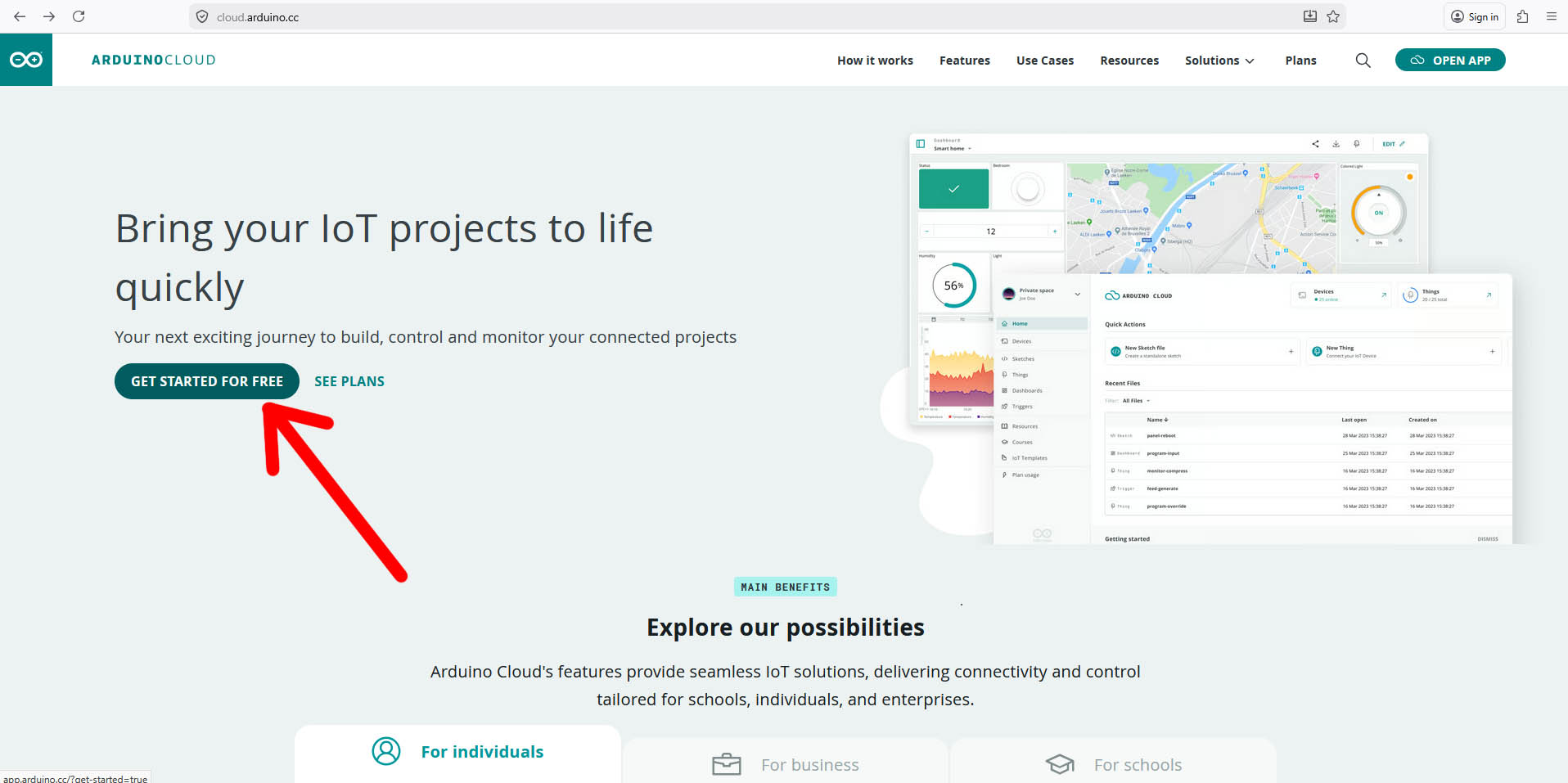
Click "Getting Started for Free"
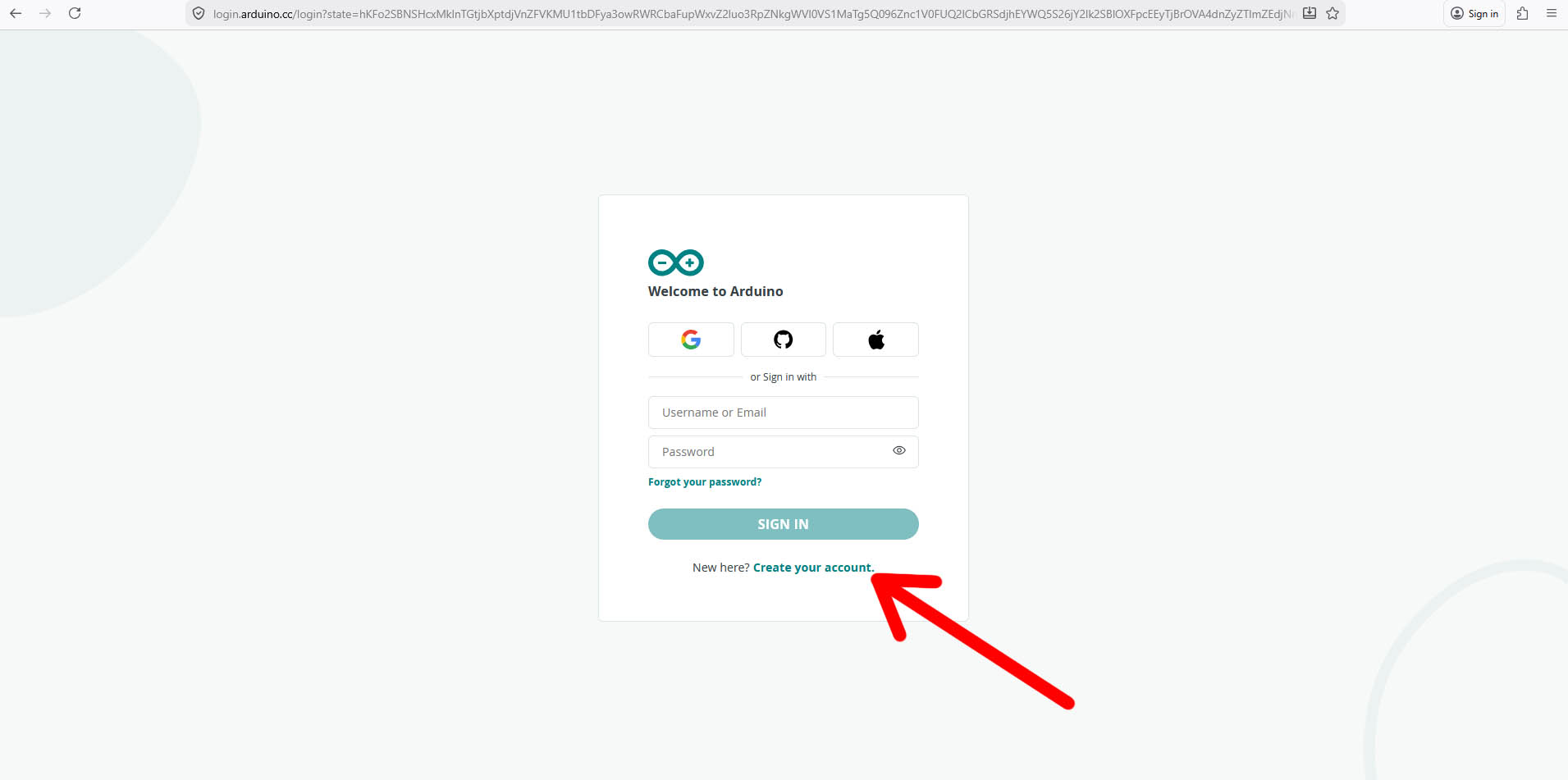
Click "Create your account"
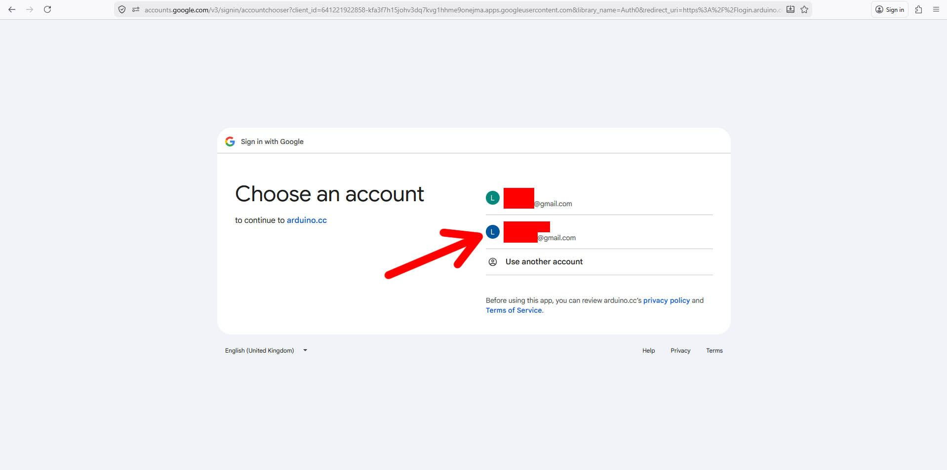
In my case, click the "Google" button
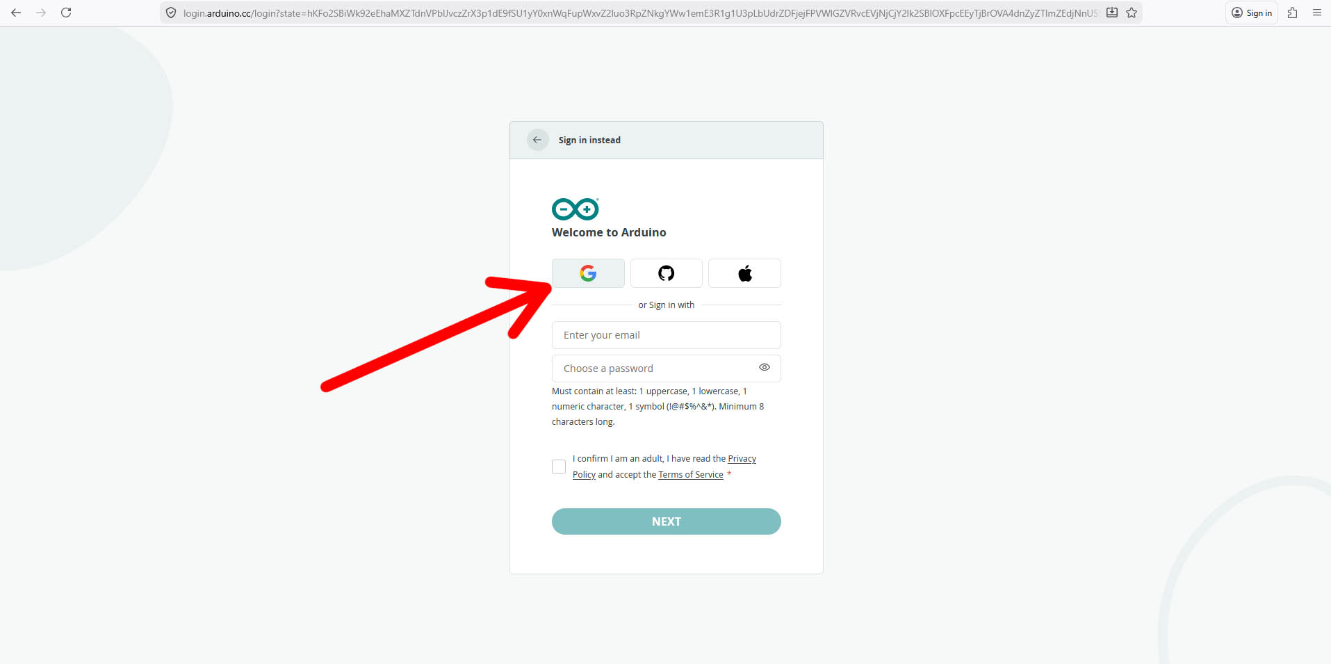
Select my prefered Google account and define my username
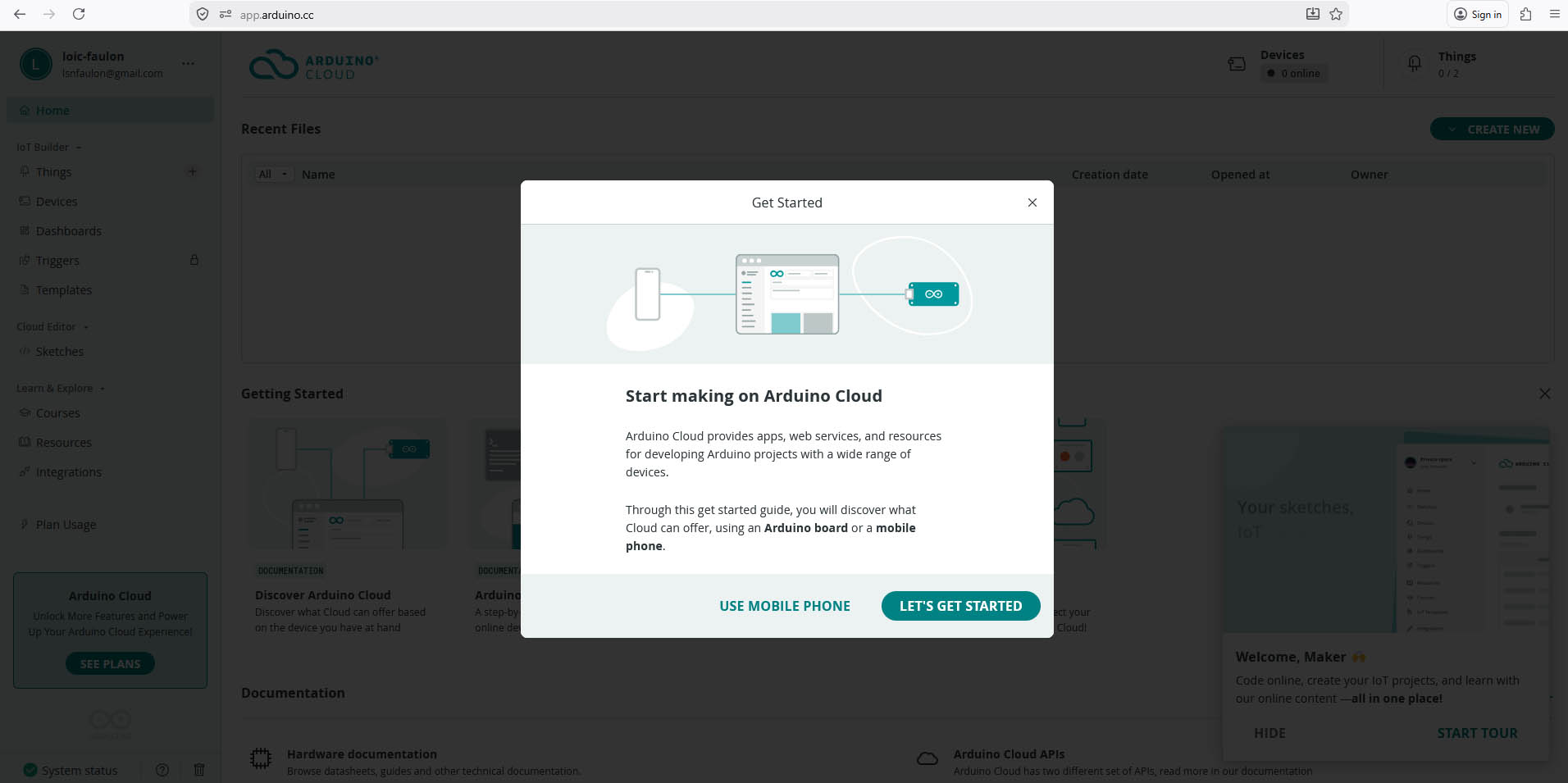
Done 😃 "LET'S GET STARTED" 😉 😉 😉
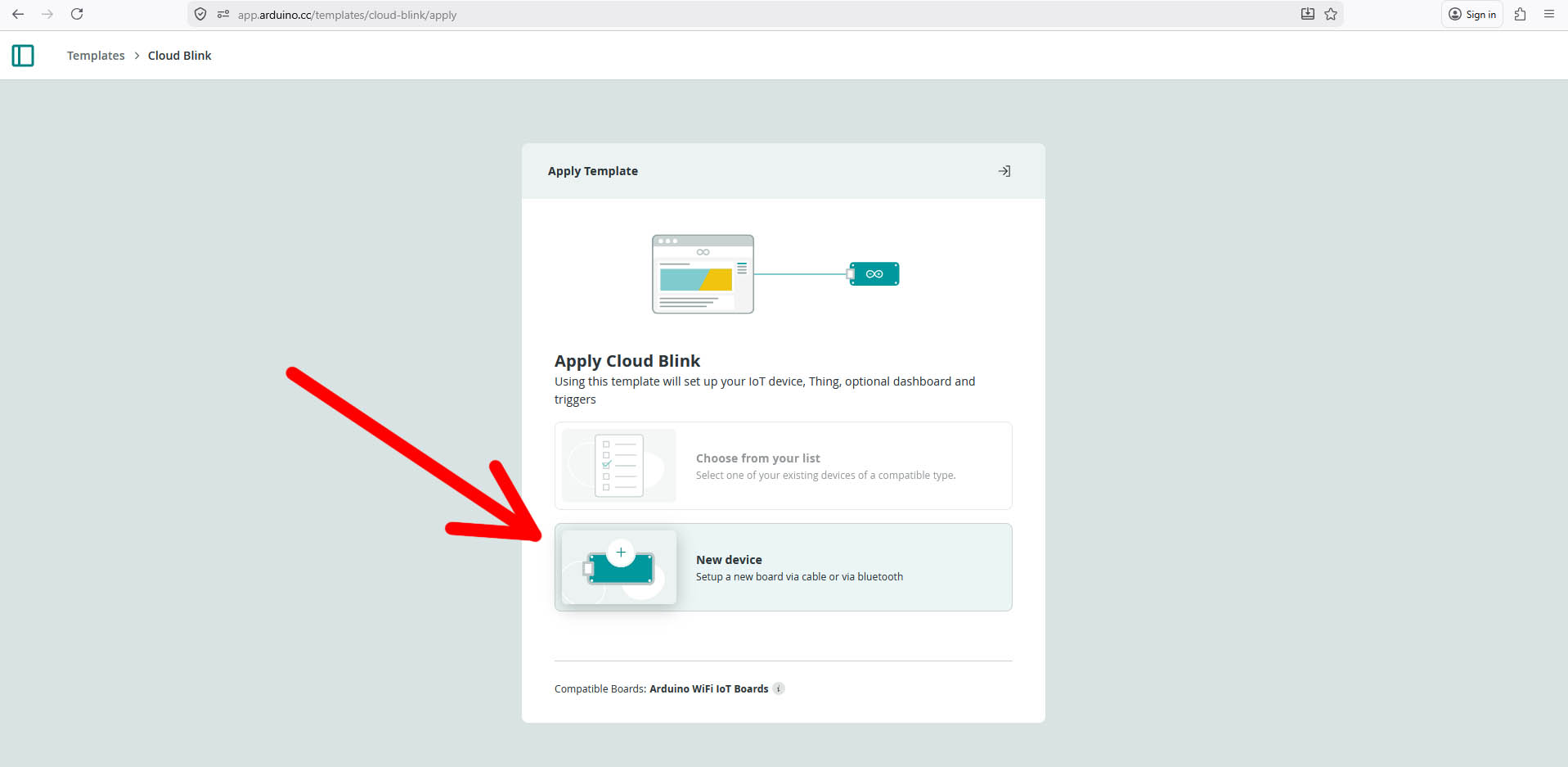
2. Register and connect a Device
Click "New Device"
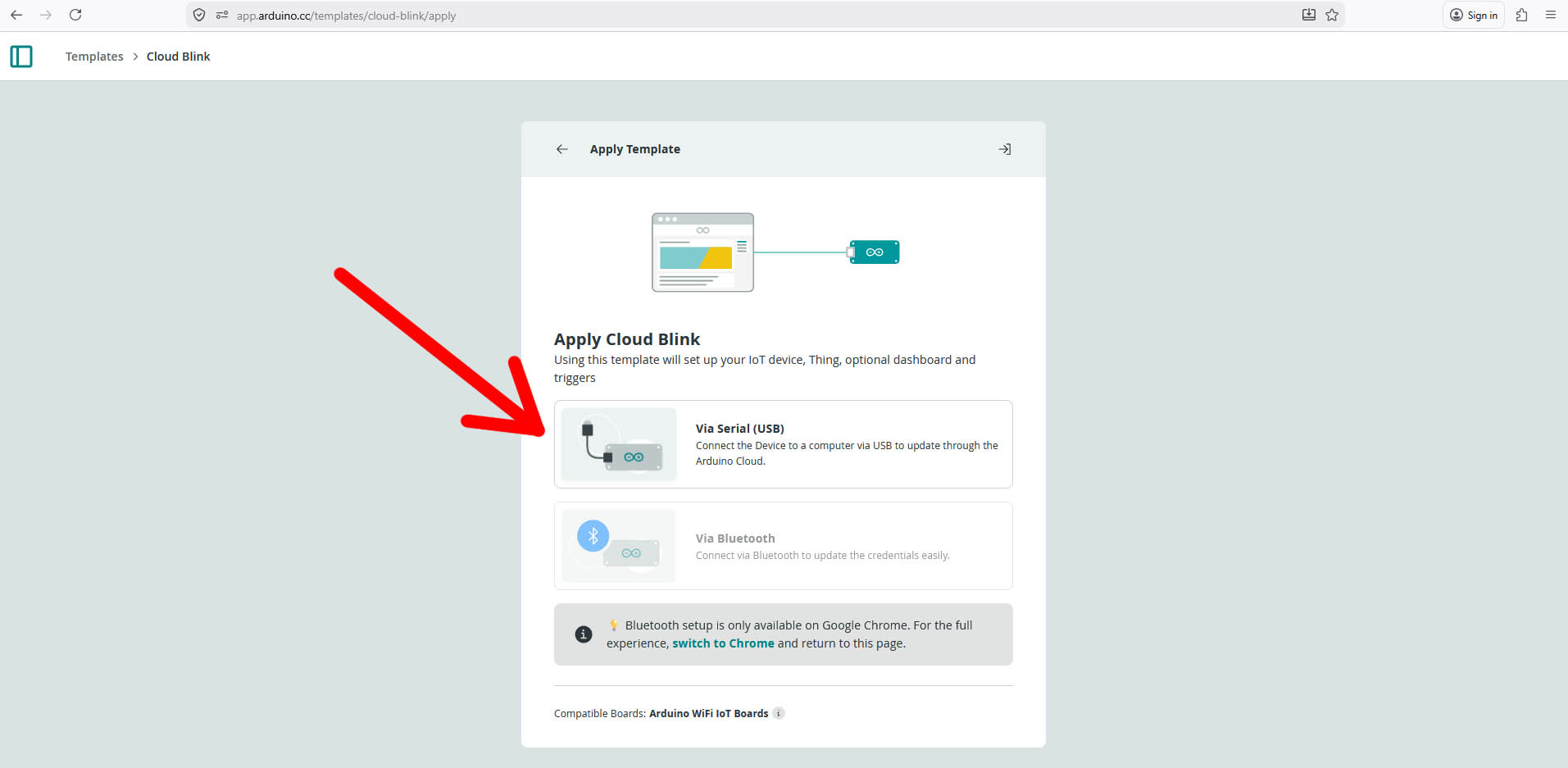
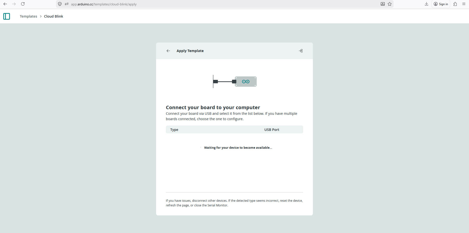
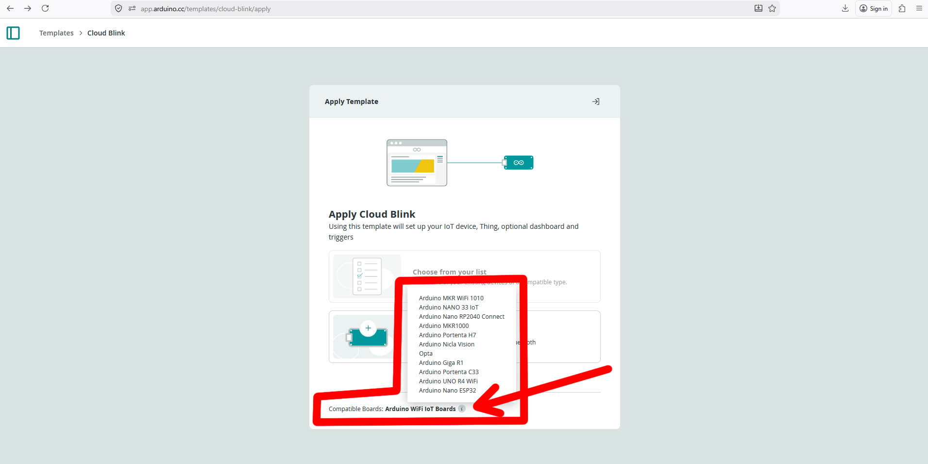
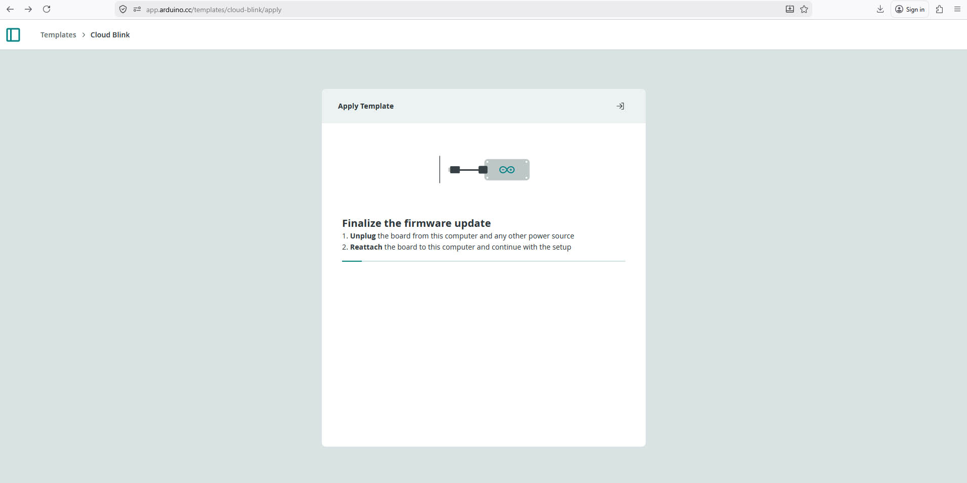
Apply Cloud Blink "Via Serial (USB)", this connects the Device to a computer via USB to update through the Arduino Cloud - Note: we need to use Google Chrome if we wish to connect via Bluetooth instead
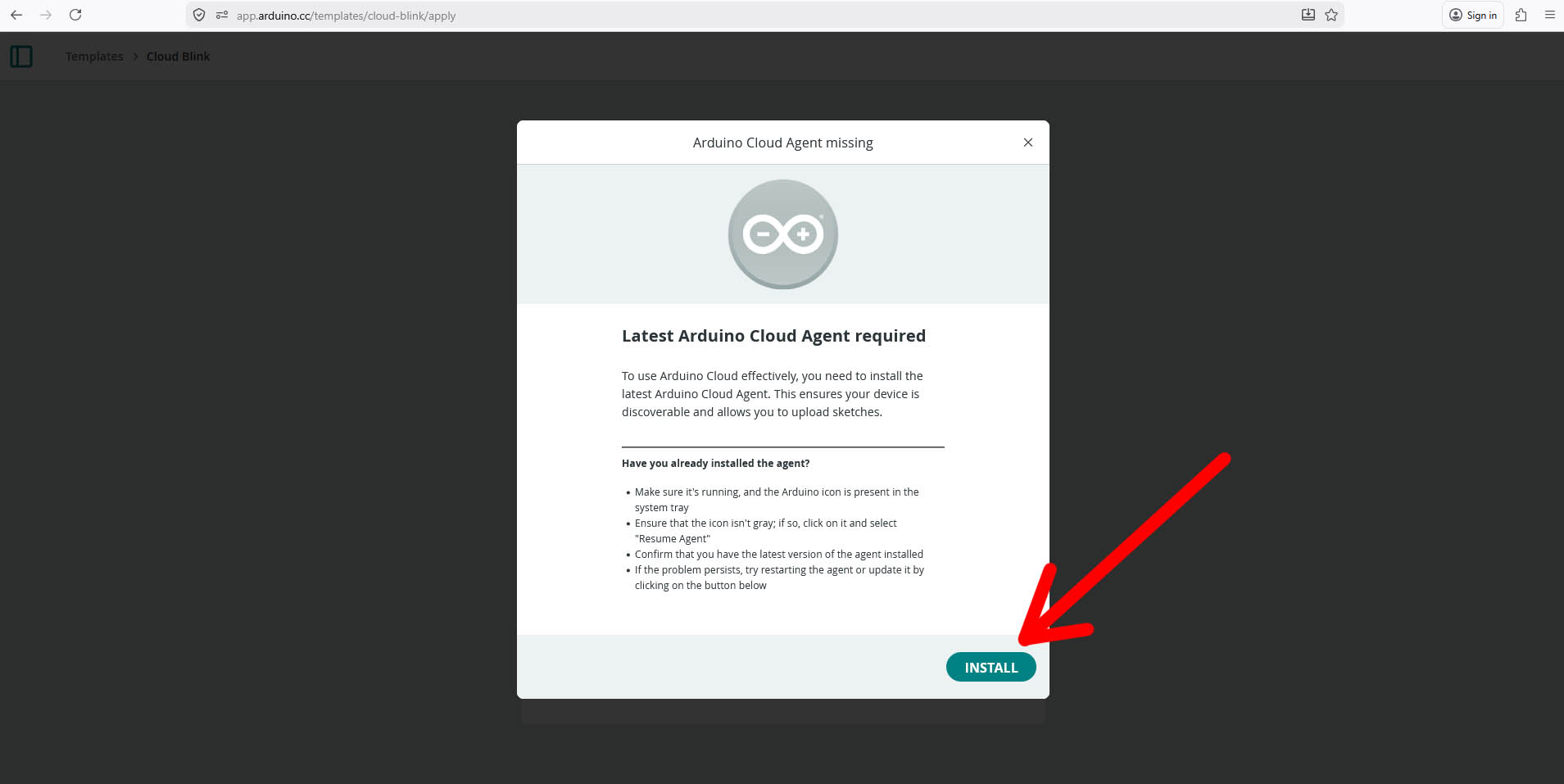
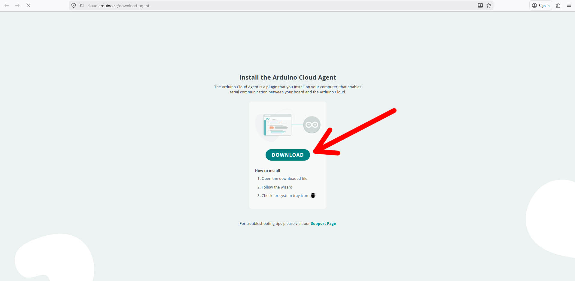
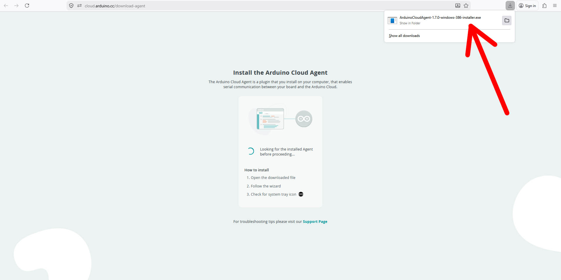
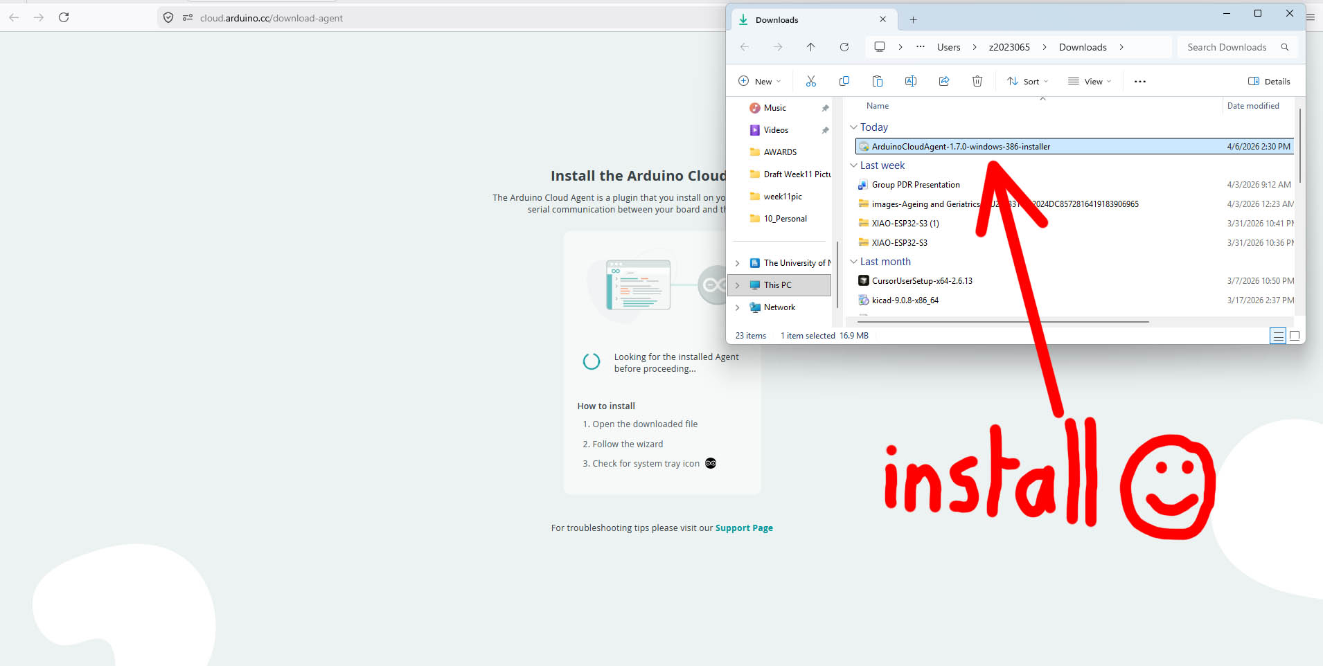
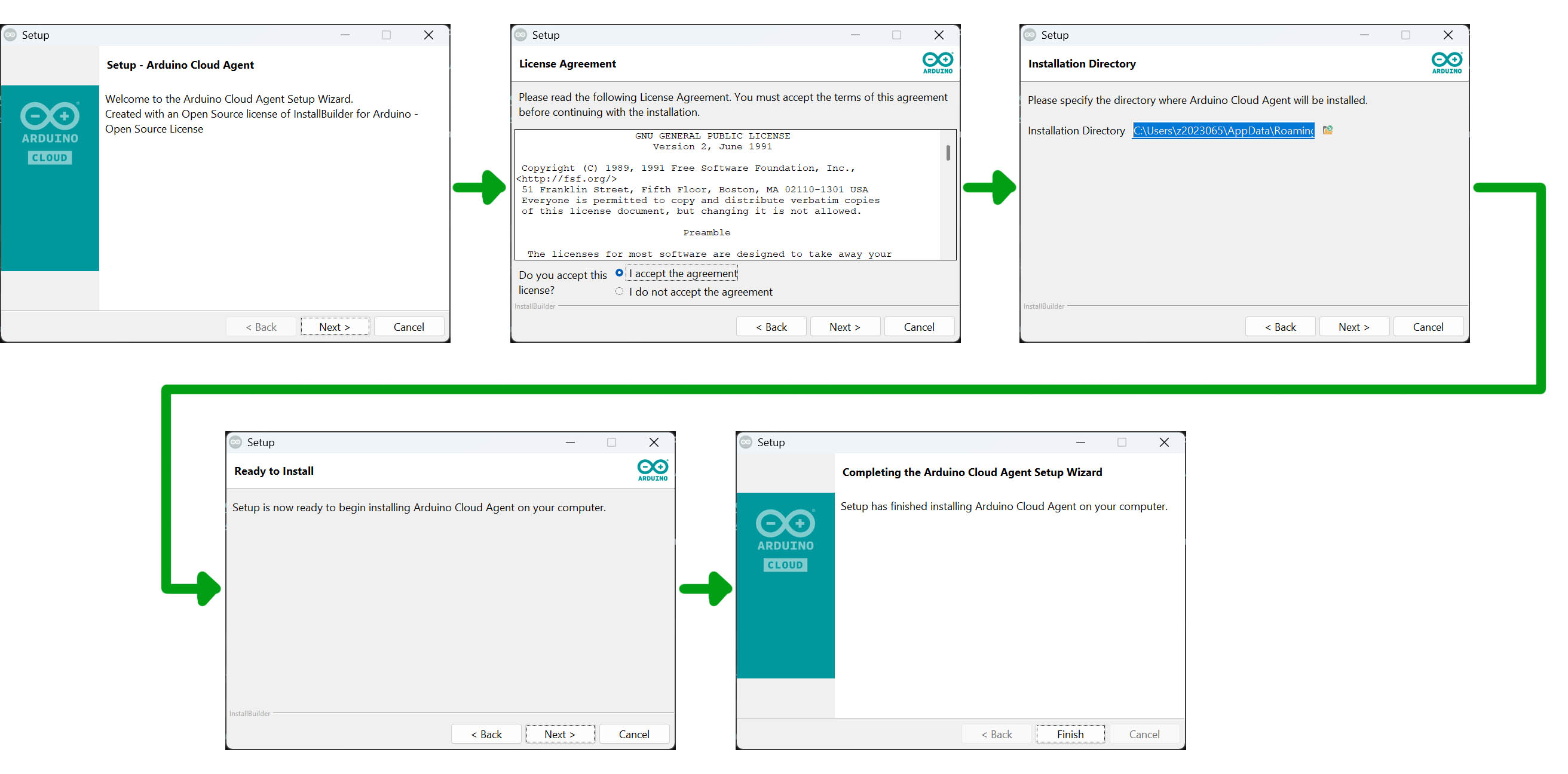
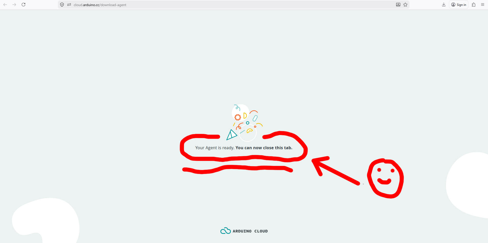
As advised, install the latest Arduino Cloud Agent by clicking "INSTALL"
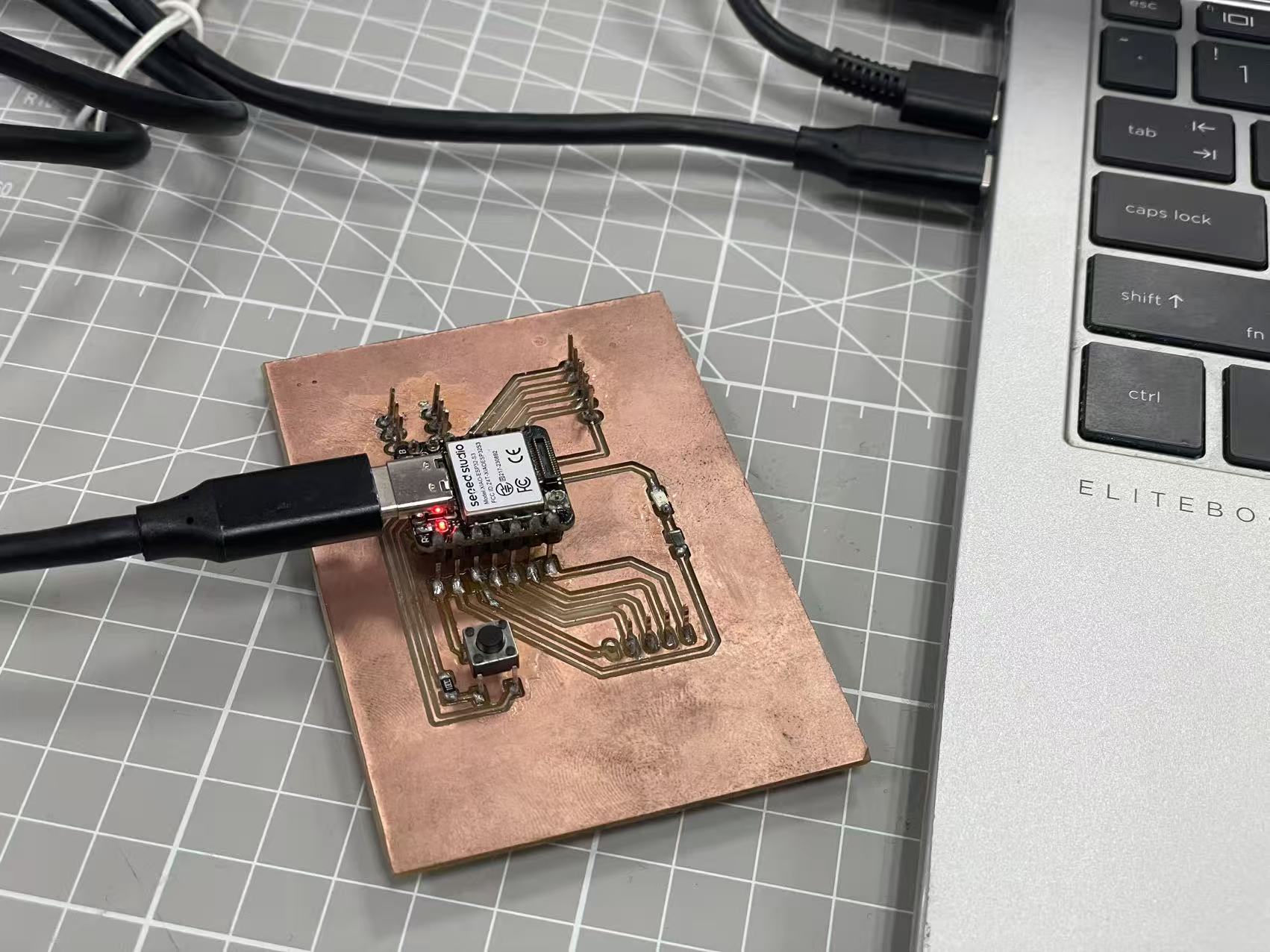
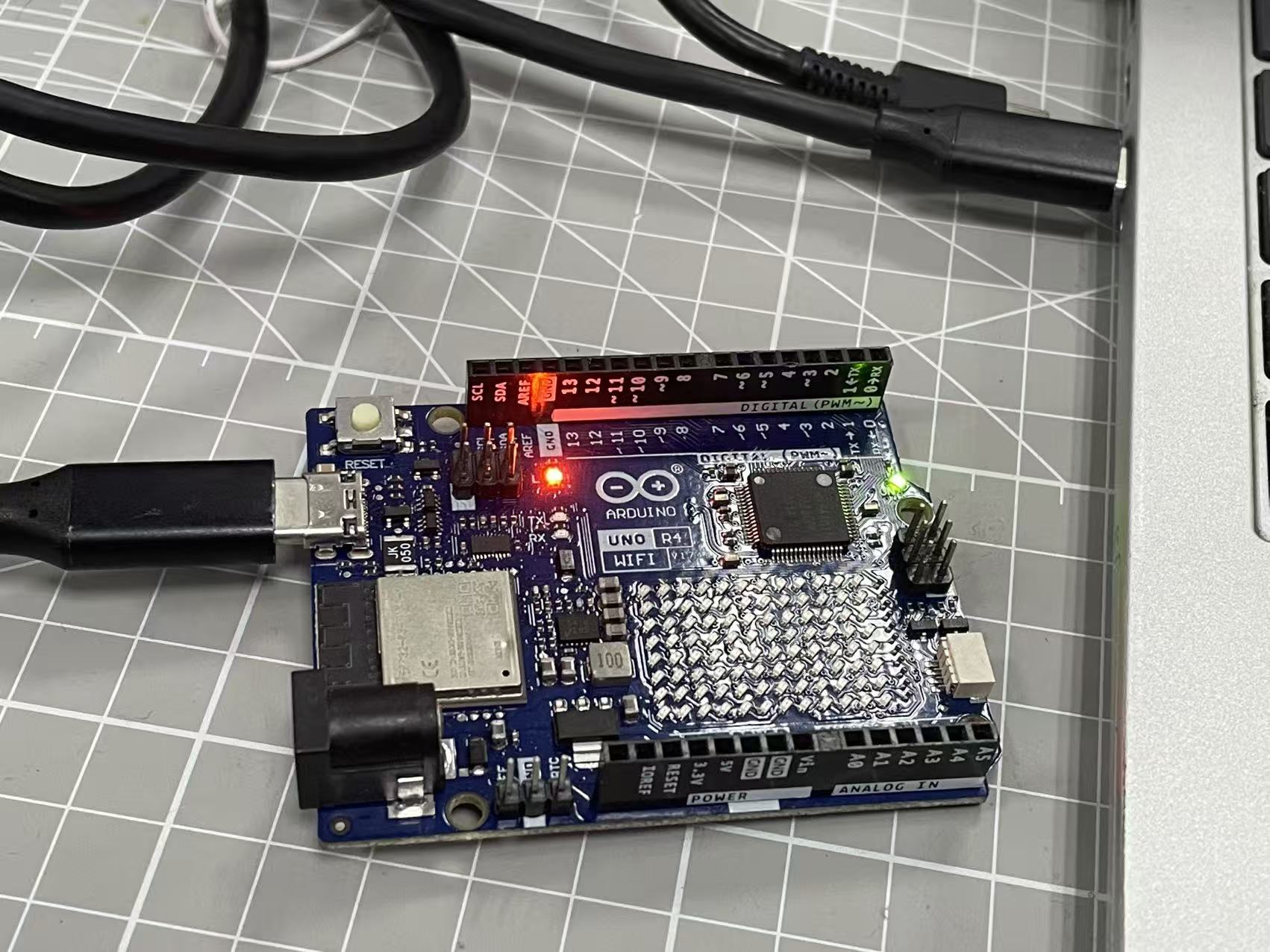
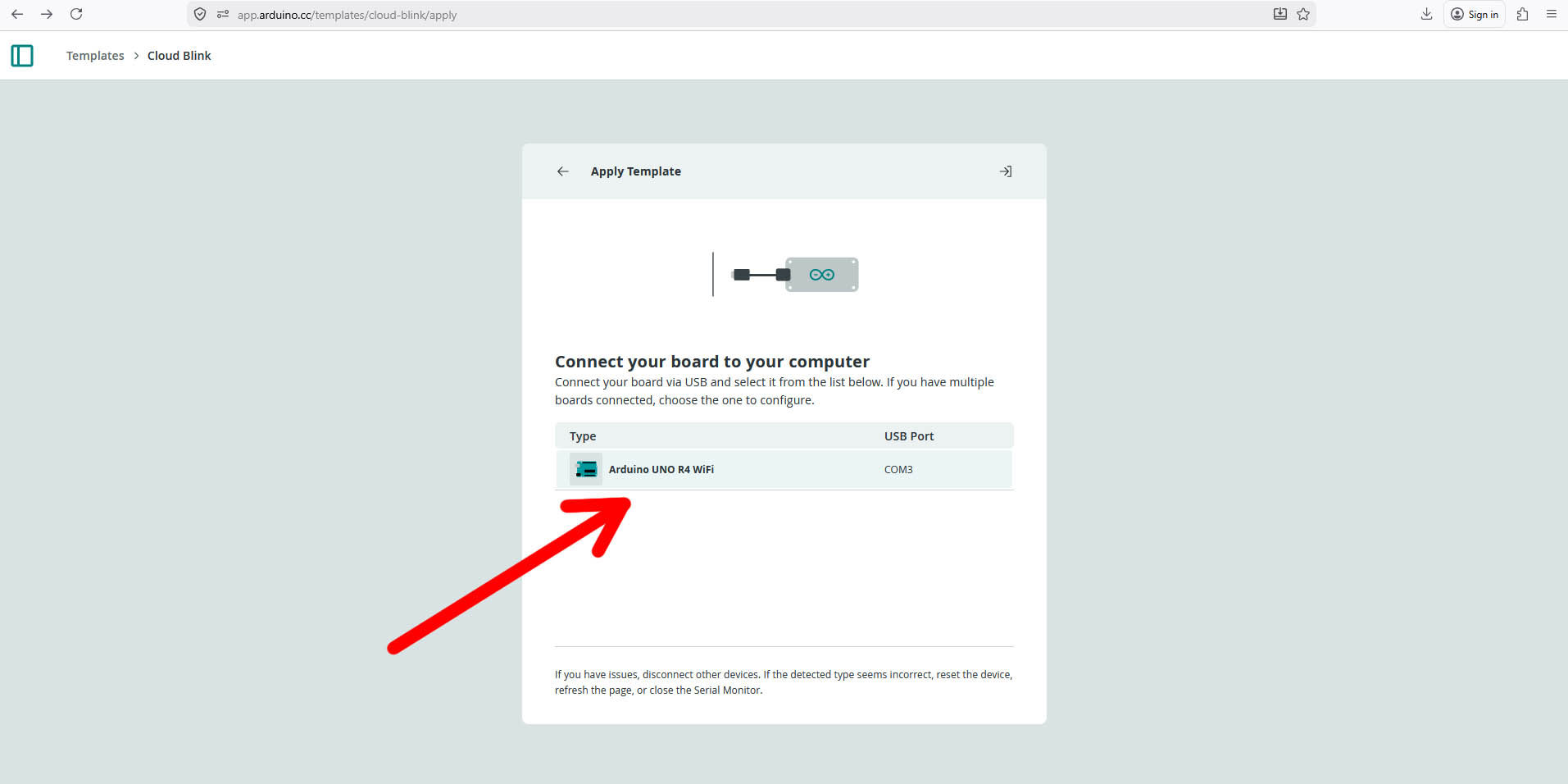
Connect my board to my computer via USB port
First trial with the XIAO ESP32-S3... It doesn't work 😦 - with this easy/quick setup I have followed, I can only use specific Arduino boards as specified in the picture below.
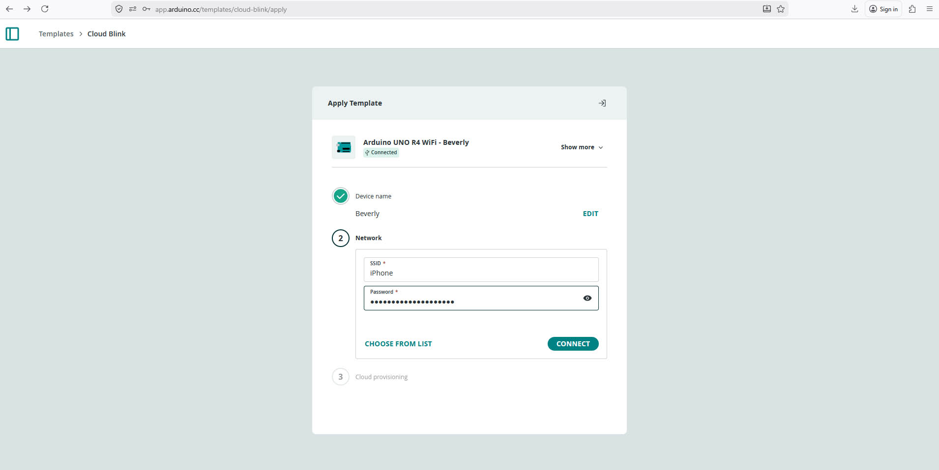
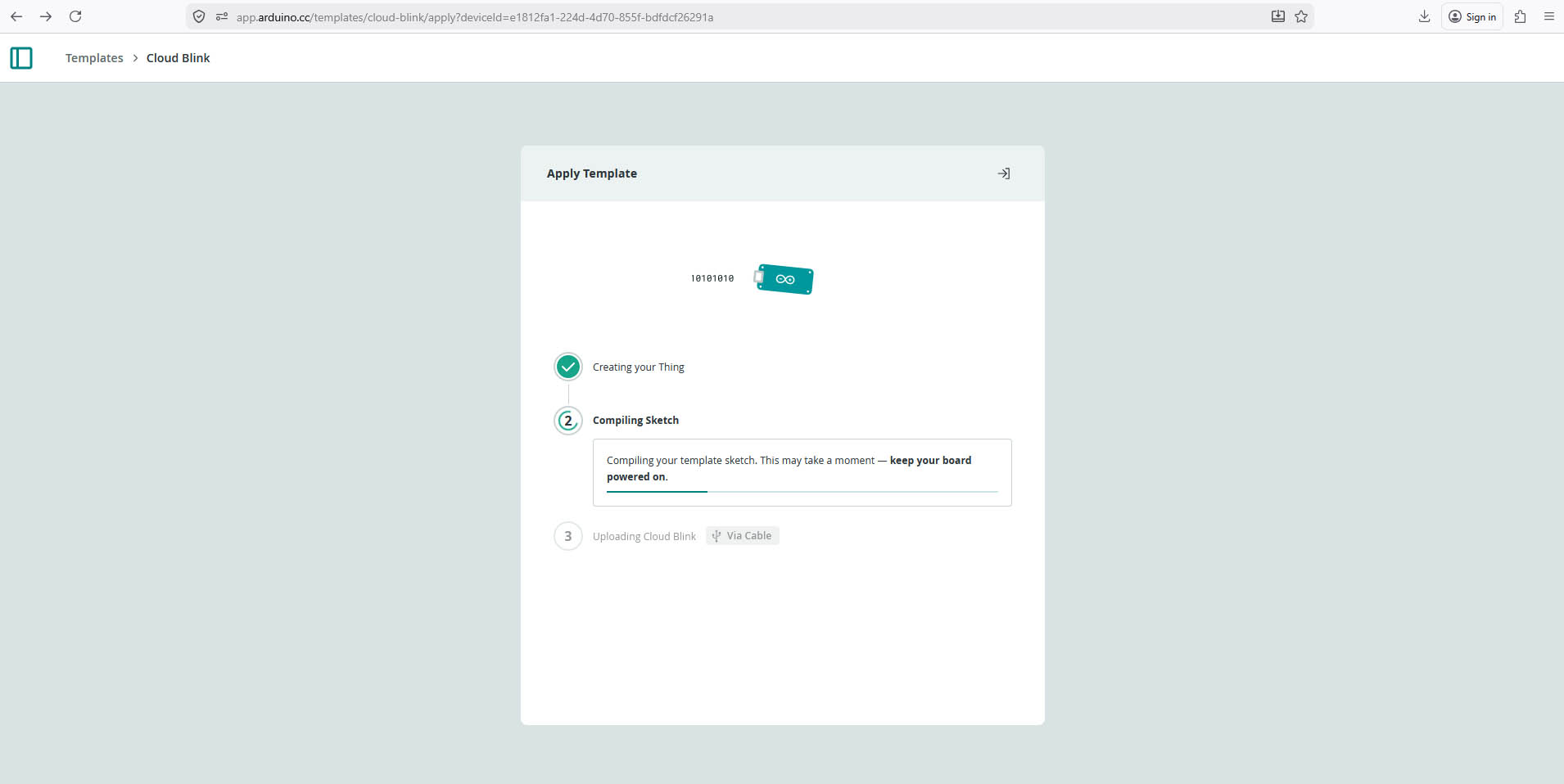
Second trial with the Arduino UNO R4... It works 😃
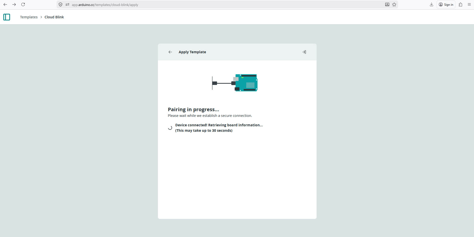
Connect to my mobile phone - Enter SSID and Password
3. Testing the Dashboard with Arduino UNO R4 Wi-Fi
- From Dashboard on my laptop... Switch on/off the LED 😃
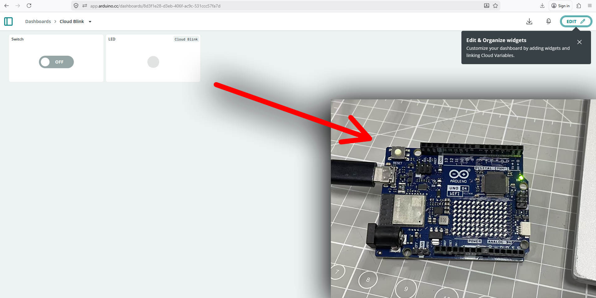
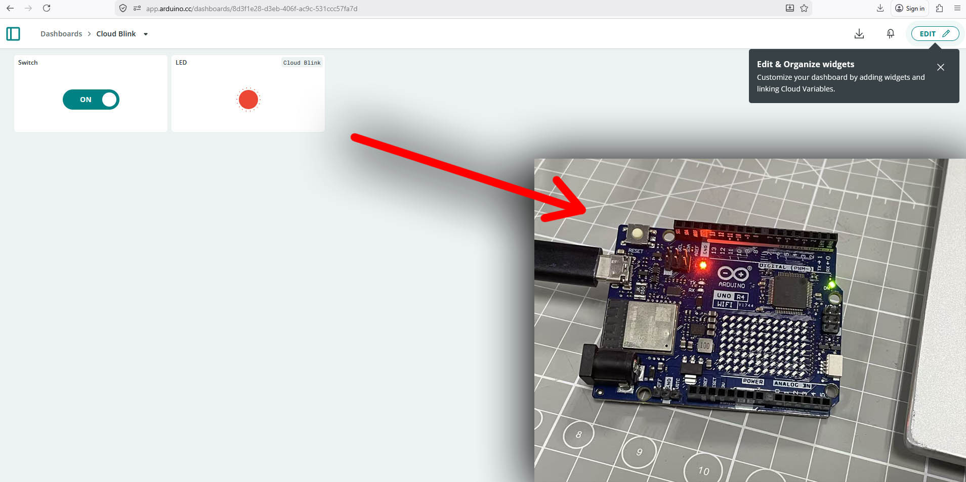
SUCCESSSSSSS!!! 😃 😃 😃
- From Dashboard on my mobile phone... Switch on/off the LED 😃
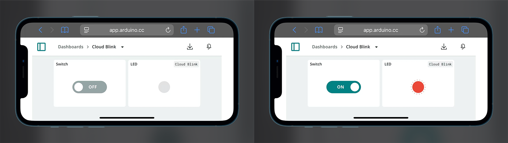
SUCCESSSSSSS!!! 😃 😃 😃
"Test ONE" with Arduino Cloud + my PCB board with Xiao ESP32-S3 + Step Motor + Obstacle Sensor
Scenario Introduction:
My test scenario aims to control a step motor using an XIAO ESP32-S3, triggered by a Flying-Fish sensor. When the sensor detects an obstacle, the motor turns 15 degrees every 2 seconds. A push button overrides the system, stopping the motor (and lighting an LED when pressed) even if the sensor is active.
The Dashboard of Arduino Cloud is used as an interface to visualise inputs and outputs and control the system.
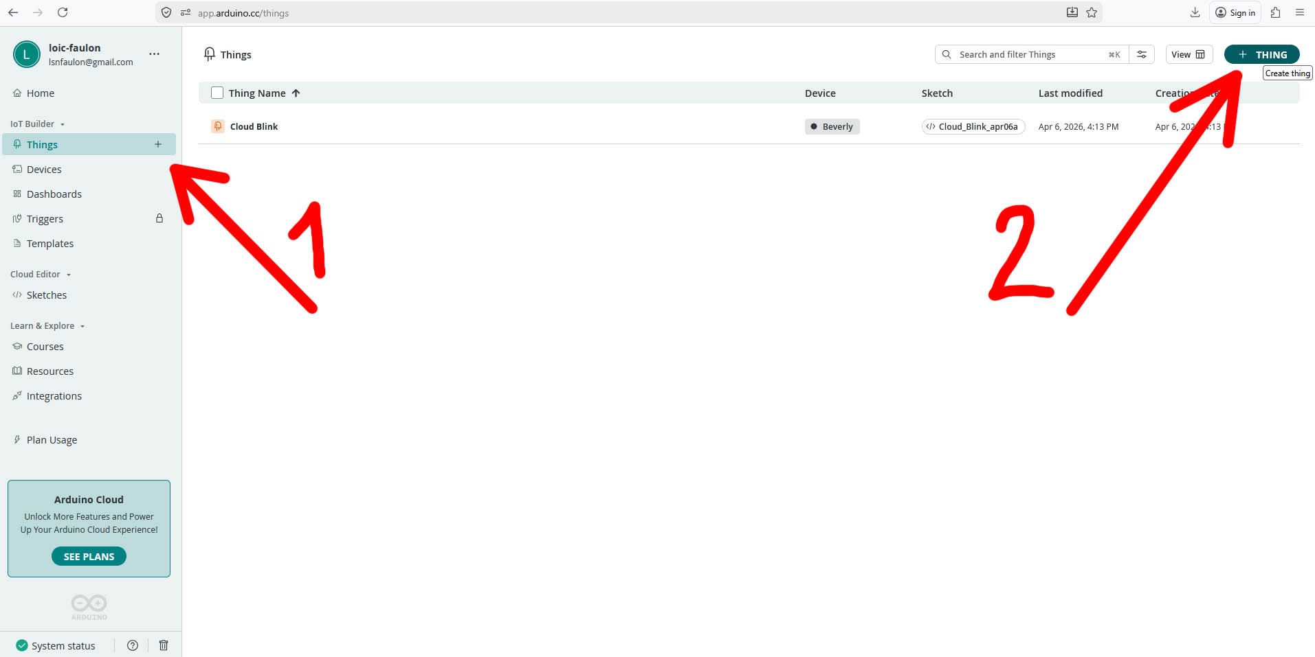
1. Create New Project
To create a New Project in Arduino Cloud, select "Things" on the left bar menu, and then click the "+THING" button on the top right corner.
Rename the Project with a relevant name
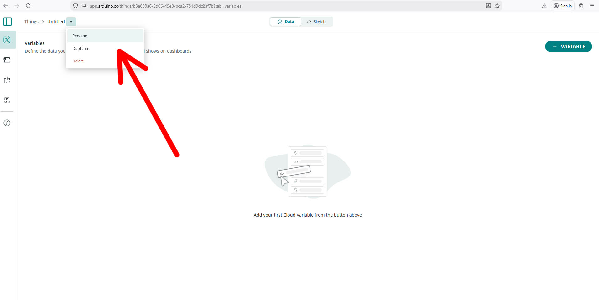
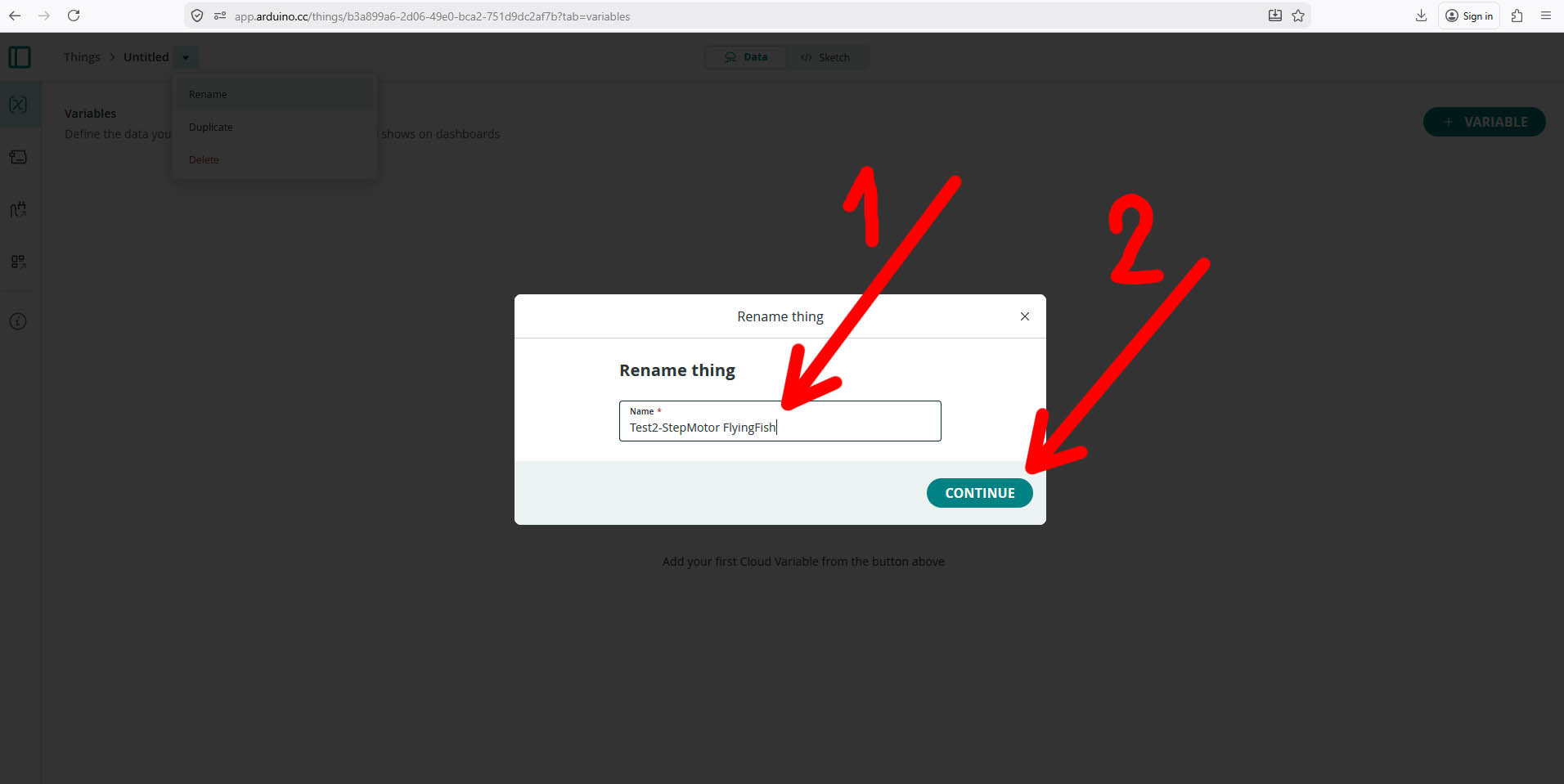
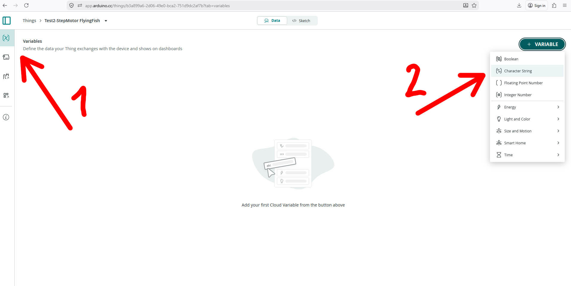
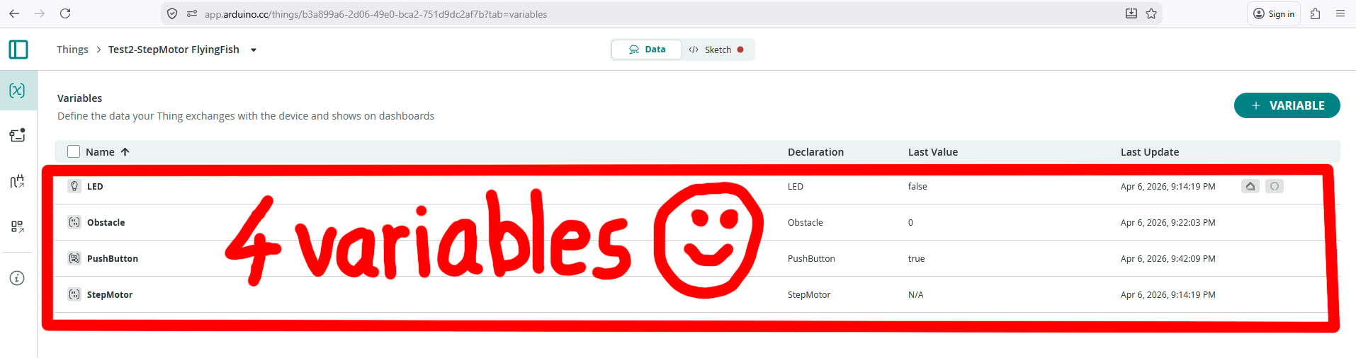
2. Define my Variables
To define my Variables in my project ("my Thing"), select the "Variables" icon (1) on the left bar menu, and click the "+VARIABLE" button (2) on the top right corner. Then, select the appropriate type of variable, give it a name (3), set the parameters (4&5), and click "CREATE" (6).
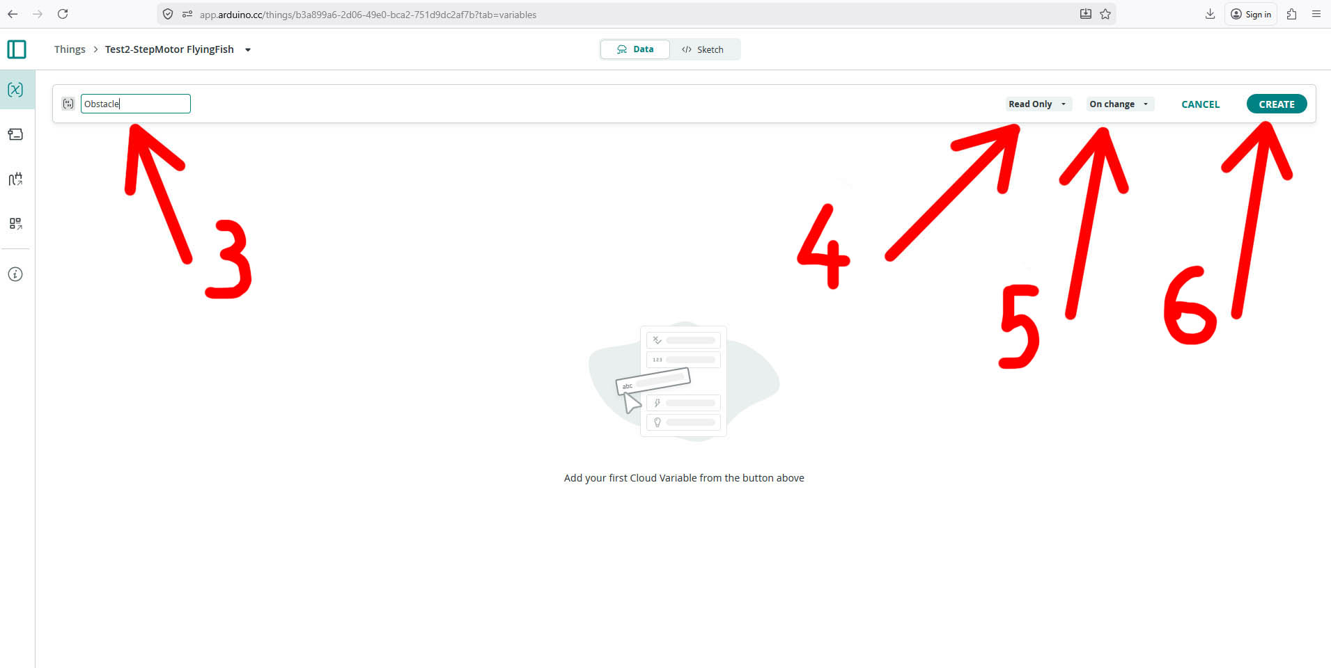
My first variable is defined:
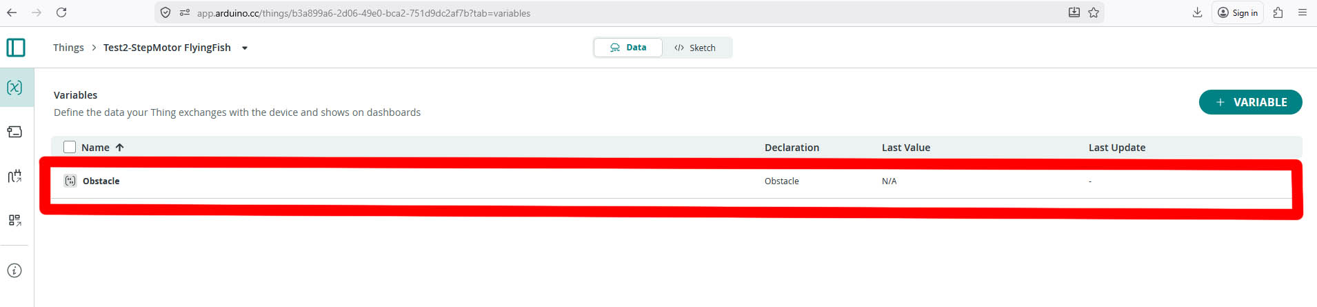
Repeat the same actions to create all my other variables: (Obstacle, PushButton, StepMotor/ LED)
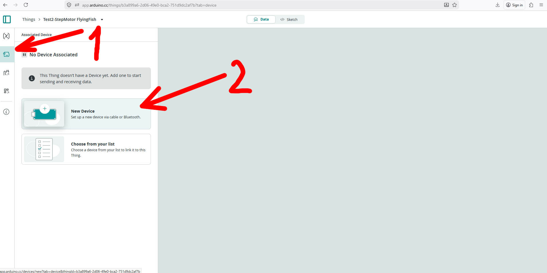
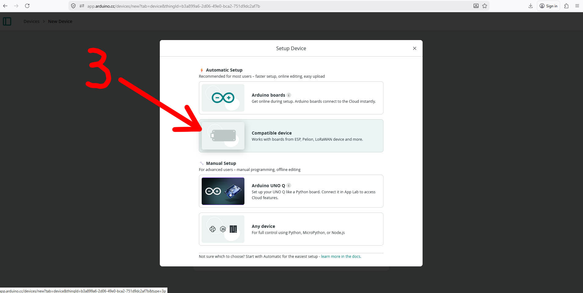
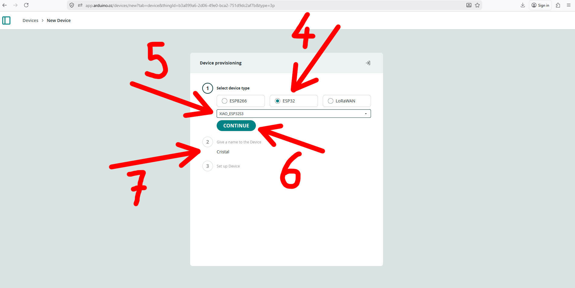
3. Device Registration and Set-up (Xiao ESP32-S3)
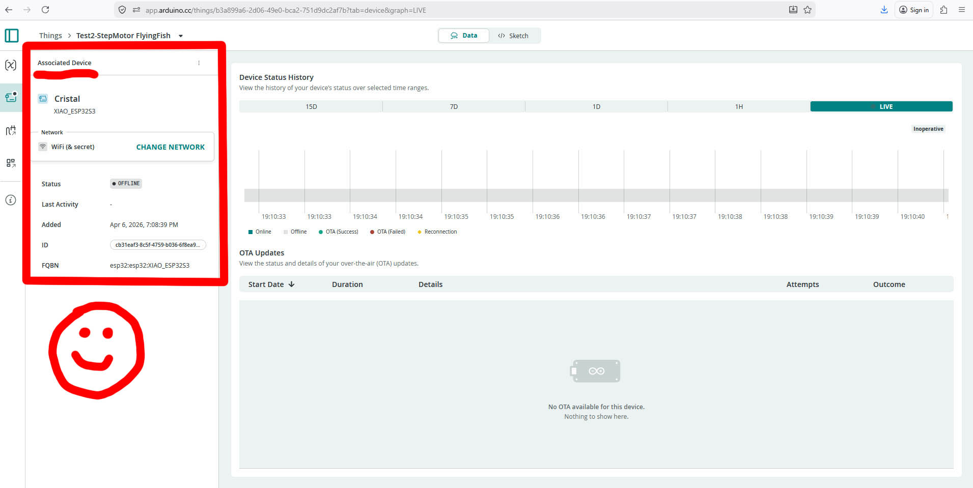
Select the "Associated Device" icon (1) on the left bar menu, and click "New Device" (2). Then, click on "Compatible Device" (3). Select "ESP32" (4), in the drop-down menu "XIAO_ESP32S3" (5), and click the "CONTINUE" button (6). Give a Name to the device (7) - e.g. Cristal (in my case).
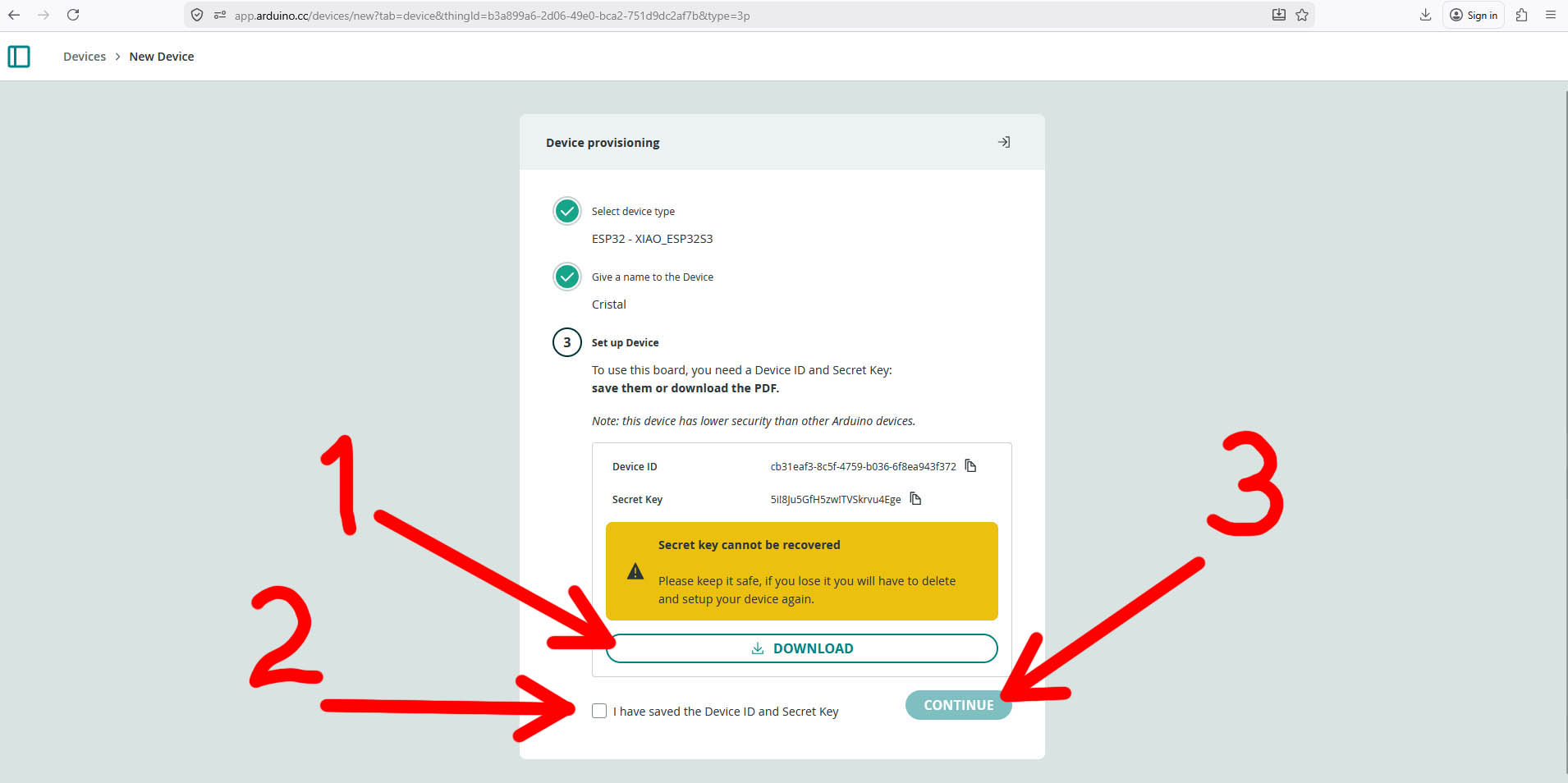
Set-up Device: Save the "Device ID" and "Secret Key" by downloading the file (1) to my laptop, tick the box "I have saved the Device ID and Secret Key" (2), and click the "CONTINUE" button (3).
4. Data Visualisation: Dashboard
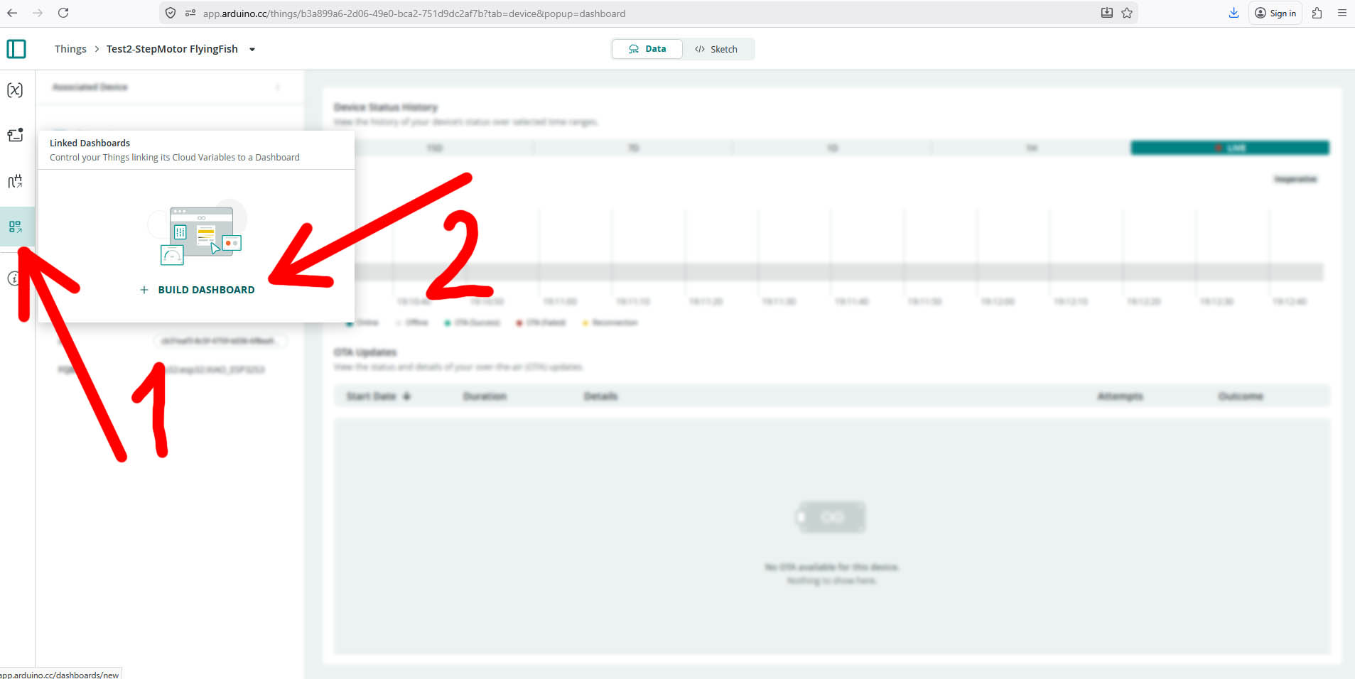
Select the "Linked Dashboards" icon (1) on the left bar menu, and click "+BUILD DASHBOARD" (2).
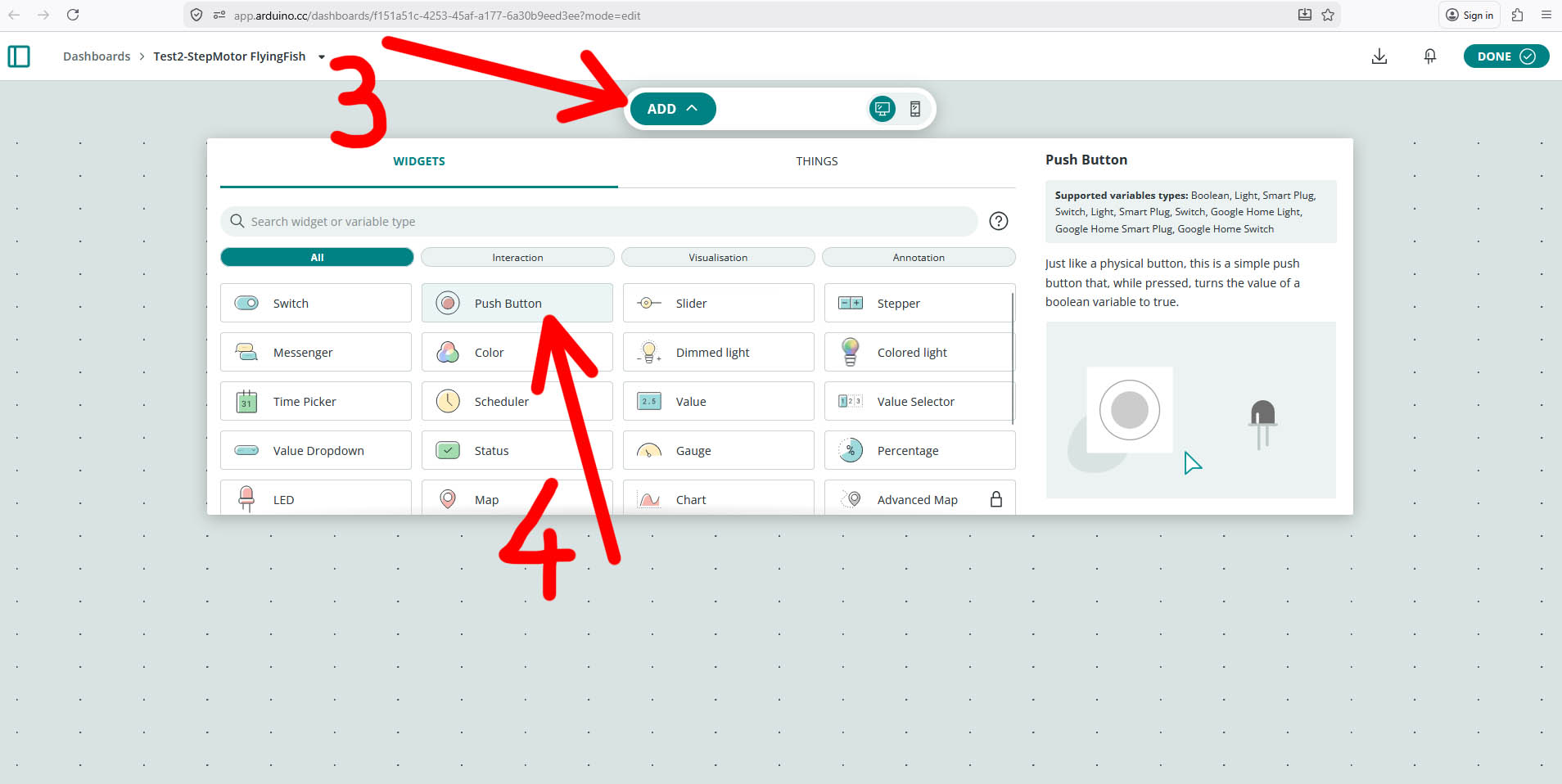
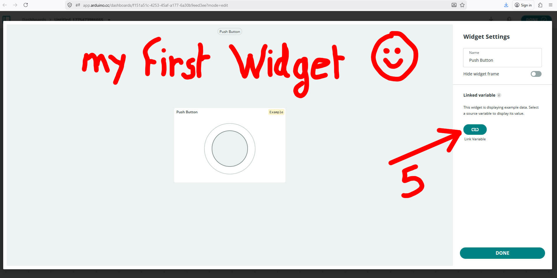
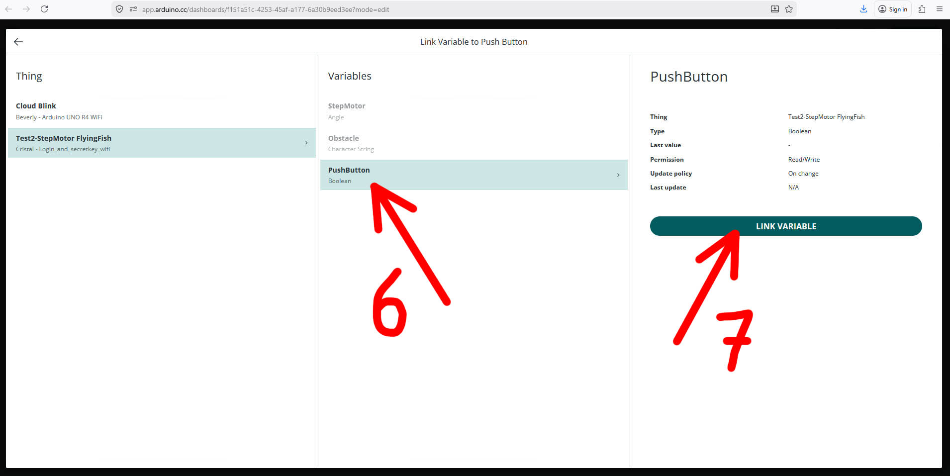
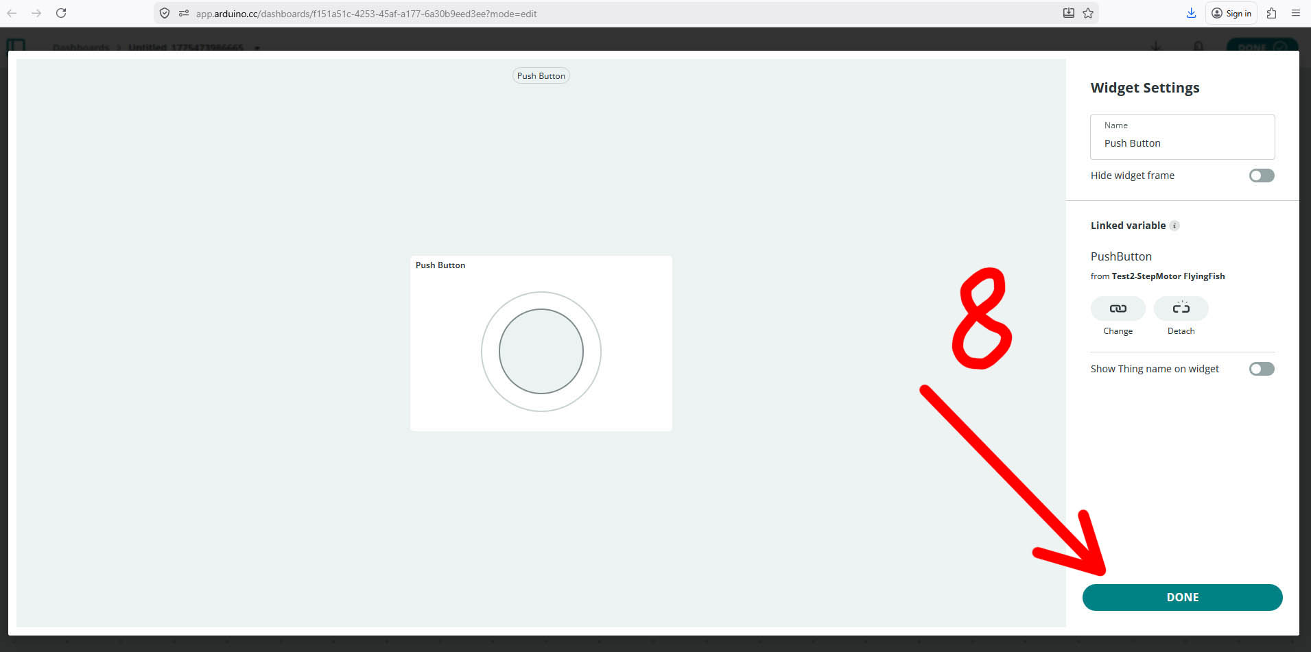
Add my first Widget component: Click "ADD" (3) and select the appropriate Widget component (4) - e.g. Push Button (in my case). Then, click the "Link Variable" button (5) and select the "PushButton" variable in the available list (6) and click the "LINK VARIABLE" button (7). Click the "DONE" button (8) to conclude this first Widget.
Repeat the same actions to add all my other Widgets, and rearrange the layout and size if necessary:
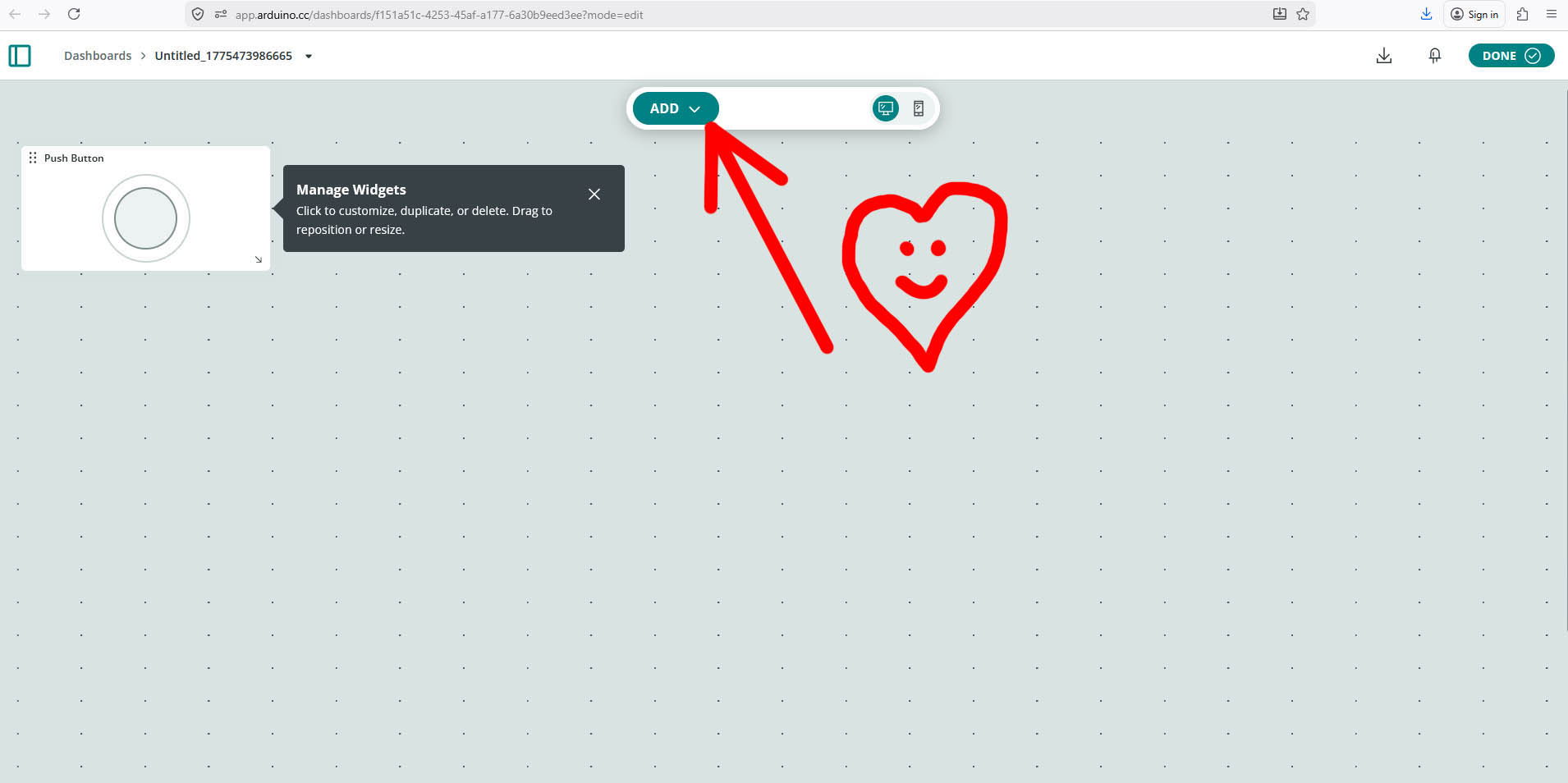
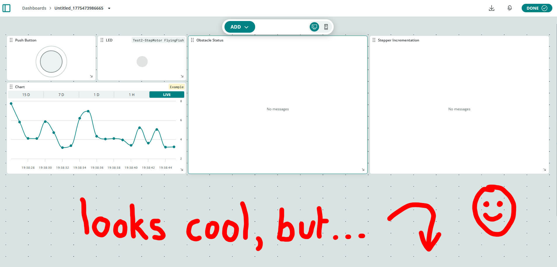
I rearranged the layout in a more compact size for better visualisation on my mobile phone... 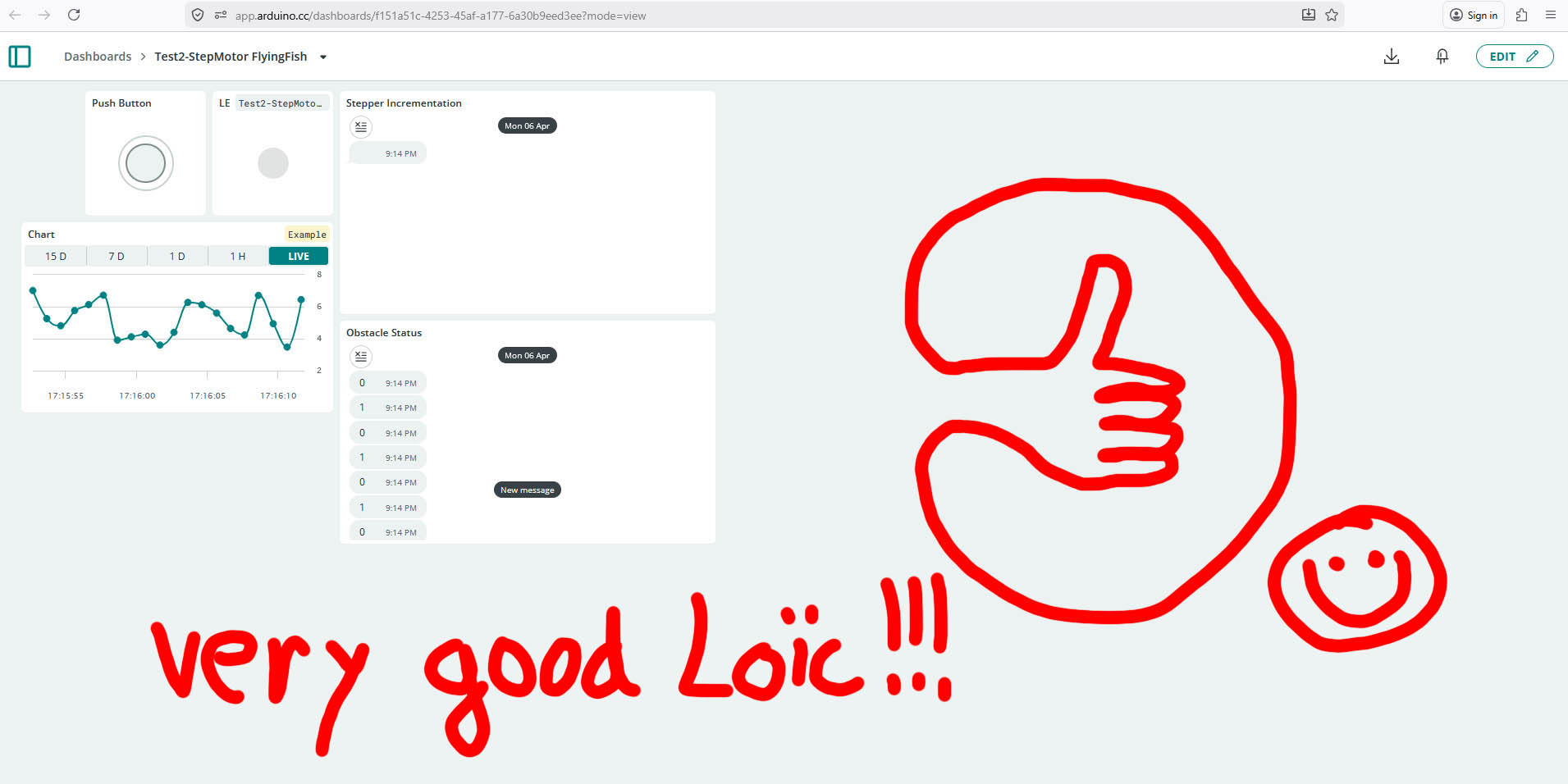
5. Code Implementation and Testing
The code implementation and testing was a failure 😦 😦 😦 ...A BIG FAILURE!!! I tried multiple ways to make it work by changing some code and even some hardware (as shown in the picture below), but I never managed to make it work completely as described in my scenario above.
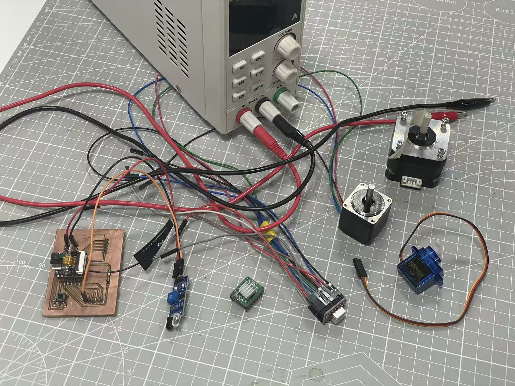
As an example, the flying-Fish sensor worked, but did not activate the step-motor... and not even the servo-motor... I also face some bad connections with the Dupont wires making it harder to identify potential issue. Time to sleep was approaching with also "Time to FAIL my Fab Academy", so I decided to go back to "basics" and created my "Test TWO" scenario as discribed below...
"Test TWO" with Processing + my PCB board with Xiao ESP32-S3 + Obstacle Sensor
Scenario Introduction:
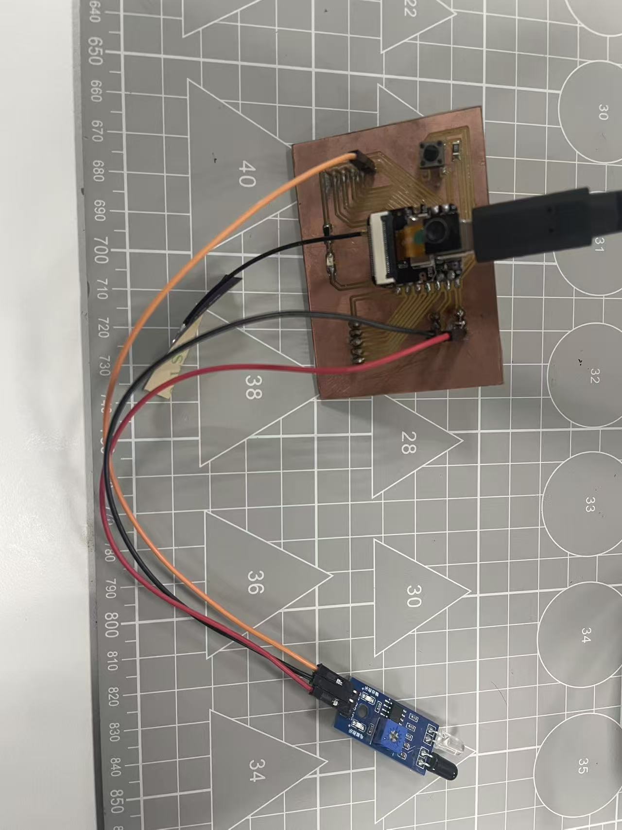
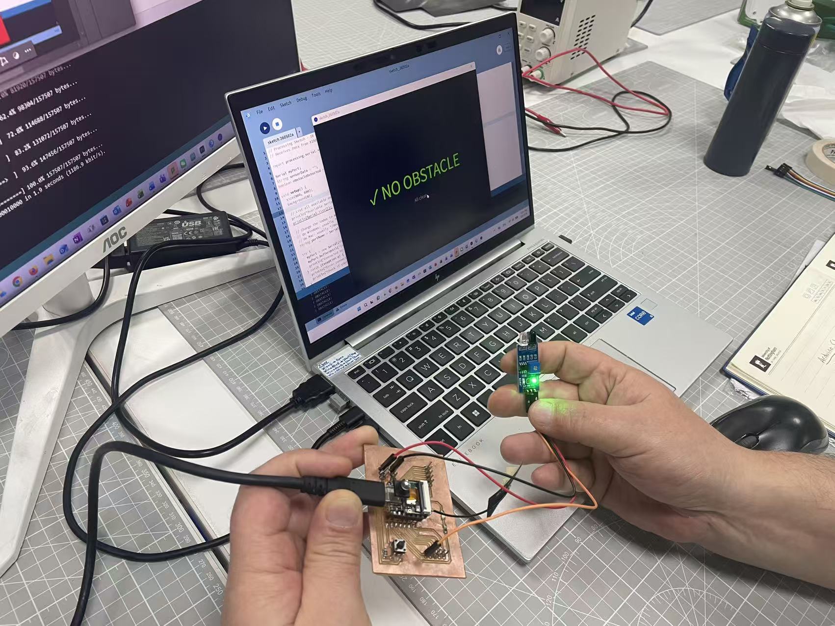
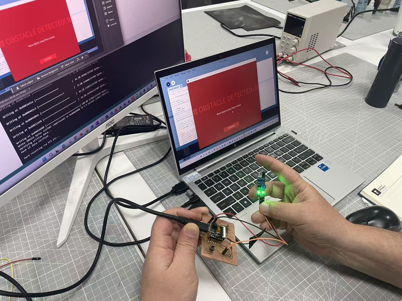
My "lifesaver" emergency test scenario using Processing (Interface Creating Software) aims to display "No Obstacle" or "Obstacle Detected" on screen, triggered by a Flying-Fish sensor which is controlled by my PCB board fitted with XIAO ESP32-S3.
1. Electronic Hardware Setup
2. Data Visualisation and Testing
3. Code Implementation
- Code for Processing Software
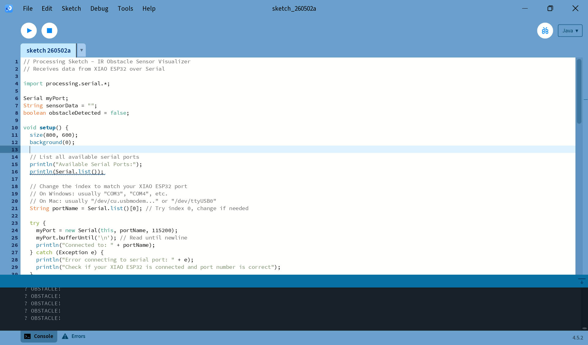
// Processing Sketch - IR Obstacle Sensor Visualizer
// Receives data from XIAO ESP32 over Serial

import processing.serial.*;

Serial myPort;
String sensorData = "";
boolean obstacleDetected = false;

void setup() {
  size(800, 600);
  background(0);

  // List all available serial ports
  println("Available Serial Ports:");
  println(Serial.list());

  // Change the index to match your XIAO ESP32 port
  // On Windows: usually "COM3", "COM4", etc.
  // On Mac: usually "/dev/cu.usbmodem..." or "/dev/ttyUSB0"
  String portName = Serial.list()[0]; // Try index 0, change if needed

  try {
    myPort = new Serial(this, portName, 115200);
    myPort.bufferUntil('\n'); // Read until newline
    println("Connected to: " + portName);
  } catch (Exception e) {
    println("Error connecting to serial port: " + e);
    println("Check if your XIAO ESP32 is connected and port number is correct");
  }

  // Set up text styling
  textAlign(CENTER, CENTER);
  textSize(48);
}

void draw() {
  // Clear background with fade effect
  fill(0, 0, 0, 50);
  rect(0, 0, width, height);

  // Display status
  if (obstacleDetected) {
    // Red background effect
    fill(255, 0, 0, 100);
    rect(0, 0, width, height);

    // Warning text
    fill(255, 0, 0);
    textSize(72);
    text("⚠️ OBSTACLE DETECTED! ⚠️", width/2, height/2 - 50);

    // Additional info
    fill(255);
    textSize(24);
    text("Move object away from sensor", width/2, height/2 + 50);

    // Flashing effect
    if (frameCount % 30 < 15) {
      fill(255, 0, 0);
      rect(width/2 - 100, height - 100, 200, 50);
      fill(255);
      textSize(20);
      text("WARNING!", width/2, height - 75);
    }
  } else {
    // Safe status
    fill(0, 255, 0);
    textSize(72);
    text("✓ NO OBSTACLE", width/2, height/2);

    fill(150);
    textSize(20);
    text("All clear", width/2, height/2 + 80);
  }
}

void serialEvent(Serial myPort) {
  // Read data from XIAO ESP32
  String data = myPort.readStringUntil('\n');
  if (data != null) {
    data = trim(data); // Remove whitespace
    sensorData = data;

    // Check if obstacle detected
    if (data.equals("OBSTACLE!")) {
      obstacleDetected = true;
      println("🔴 " + data);
    } else {
      obstacleDetected = false;
    }
  }
}- Code for Arduino IDE
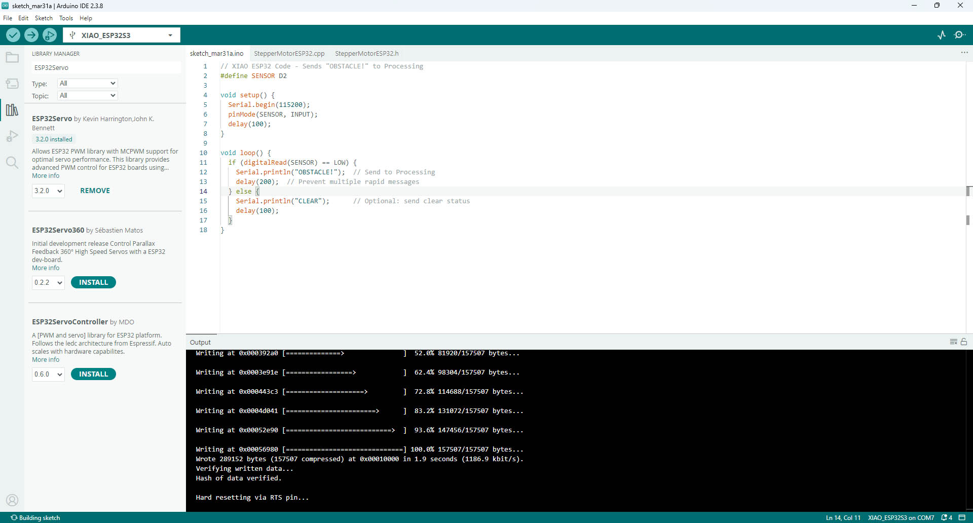
// XIAO ESP32 Code - Sends "OBSTACLE!" to Processing
#define SENSOR D2

void setup() {
  Serial.begin(115200);
  pinMode(SENSOR, INPUT);
  delay(100);
}

void loop() {
  if (digitalRead(SENSOR) == LOW) {
    Serial.println("OBSTACLE!");  // Send to Processing
    delay(200);  // Prevent multiple rapid messages
  } else {
    Serial.println("CLEAR");      // Optional: send clear status
    delay(100);
  }
}