Appearance
WEEK 4 – Embedded Programming
Assignments
Group Assignment
- Demonstrate and compare the toolchains and development workflows for available embedded architectures
Individual Assignment
- Browse through the data sheet for a microcontroller
- Write and test a program for an embedded system using a microcontroller to interact (with input &/or output devices) and communicate (with wired or wireless connections)
- Extra credit: assemble the system
- Extra credit: try different languages &/or development environments
Group Work
Core Specifications
| Description | |
|---|---|
| Processor | Broadcom BCM2712 2.4GHz quad-core 64-bit Arm Cortex-A76 CPU, with Cryptographic Extension, 512KB per-core L2 caches, and a 2MB shared L3 cache |
| Features | - VideoCore VII GPU, supporting OpenGL ES 3.1, Vulkan 1.2 |
| Dual 4Kp60 HDMI® display output with HDR support | |
| 4Kp60 HEVC decoder | |
| LPDDR4X-4267 SDRAM (options for 1GB, 2GB, 4GB, 8GB and 16GB) | |
| Dual-band 802.11ac Wi-Fi® | |
| Bluetooth 5.0 / Bluetooth Low Energy (BLE) | |
| microSD card slot, with support for high-speed SDR104 mode | |
| 2 × USB 3.0 ports, supporting simultaneous 5Gbps operation | |
| 2 × USB 2.0 ports | |
| Gigabit Ethernet, with PoE+ support (requires separate PoE+ HAT) | |
| 2 × 4-lane MIPI camera/display transceivers | |
| PCIe 2.0 x1 interface for fast peripherals (requires separate M.2 HAT or other adapter) | |
| 5V/5A DC power via USB-C, with Power Delivery support | |
| Raspberry Pi standard 40-pin header | |
| Real-time clock (RTC), powered from external battery | |
| Power button | |
| Operating temperature | 0℃ to 70℃ |
| Production lifetime | Raspberry Pi 5 will remain in production until at least January 2036 |
Individual Work
1. The board: Arduino UNO R4 WiFi
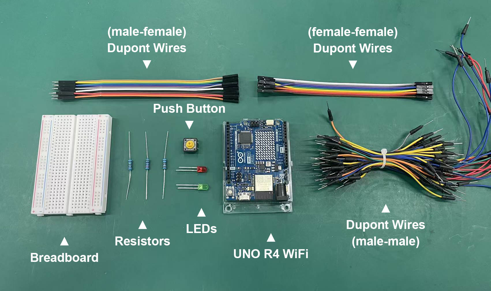
For this week I used an Arduino UNO R4 WiFi, together with a breadboard, jumper wires, two LEDs, resistors and a push button.
The main microcontroller is the Renesas RA4M1 (part number R7FA4M1AB3CFM), an Arm Cortex-M4 running at 48 MHz. The board also has an ESP32-S3 module that handles Wi-Fi and Bluetooth (Arduino UNO R4 WiFi documentation).
I browsed the UNO R4 WiFi datasheet and noted what mattered for my circuits:
| Feature | Value | Why it matters for me |
|---|---|---|
| Memory | 256 kB flash, 32 kB SRAM, 8 kB data flash (EEPROM) | Plenty of room for small sketches |
| Operating voltage | 5 V (the ESP32-S3 runs at 3.3 V) | My LEDs and button are powered from 5 V |
| Digital I/O | 14 pins, 6 with PWM (D3, D5, D6, D9, D10, D11) | I used D3 (button), D4 and D8 (LEDs) |
| Analog inputs | 6 (A0–A5), 14-bit ADC | For sensors later |
| Current per I/O pin | Up to 8 mA | This is why each LED needs a series resistor |
| Communication | USB-C (programming and serial), 1× UART, 2× I2C, 1× SPI, 1× CAN | I used USB serial to upload code and send data to the computer |
The most useful point for me was the 8 mA limit per pin. An LED connected without a resistor could draw more current than this and damage the pin.
2. Simulation in Tinkercad
Before touching the real board, I tested my circuits in Tinkercad Circuits. Tinkercad only offers the Arduino Uno R3, but the simple digitalRead/digitalWrite code I wrote works the same way on the UNO R4, so I could reuse it without changes.
2.1. Warm-up: two blinking LEDs (output only)
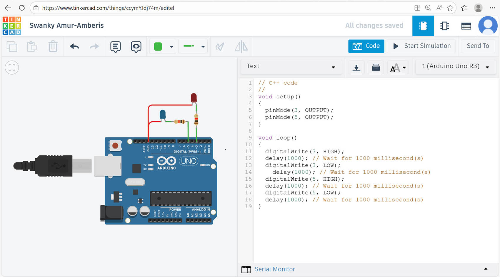
I connected a red LED to D3 and a blue LED to D5, each through a resistor (220Ω), and wrote a sketch that switches them on and off one after the other.
void setup() {
  pinMode(3, OUTPUT);
  pinMode(5, OUTPUT);
}

void loop() {
  digitalWrite(3, HIGH);
  delay(1000);            // wait 1 s
  digitalWrite(3, LOW);
  delay(1000);
  digitalWrite(5, HIGH);
  delay(1000);
  digitalWrite(5, LOW);
  delay(1000);
}
Test 1: In a second version I removed two of the delay() lines. The LEDs then alternate directly, with no dark pause in between. This showed me how the timing of the loop controls the sequence.
Test 2:
2.2. Scenario 1: push button controls two LEDs (input + output)
Next I added an input. A push button is connected to pin D3, with a pull-down resistor so the pin reads LOW when the button isn't pressed. A red LED is on pin D8 and a green LED on pin D4.
- Button not pressed → red LED on, green LED off.
- Button pressed → green LED on, red LED off.
const int LED1 = 8;   // red LED
const int LED2 = 4;   // green LED
int val = 0;          // button state

void setup() {
  pinMode(LED1, OUTPUT);
  pinMode(LED2, OUTPUT);
  pinMode(3, INPUT);  // push button
}

void loop() {
  val = digitalRead(3);
  if (val == HIGH) {          // button pressed
    digitalWrite(LED2, HIGH);
    digitalWrite(LED1, LOW);
  } else {                    // button released
    digitalWrite(LED1, HIGH);
    digitalWrite(LED2, LOW);
  }
  delay(1000);
}
Because of delay(1000), the board only checks the button once per second, so the LEDs can take up to a second to react. A shorter delay would make the button feel more responsive.
Scenario 1 circuit and code in Tinkercad: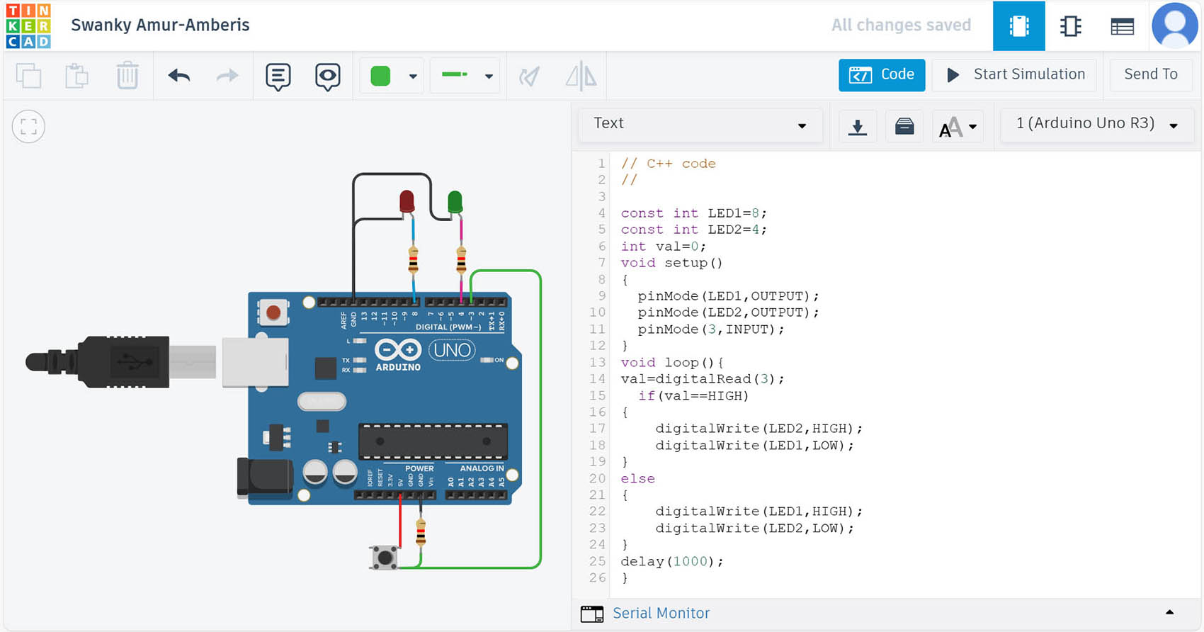
Scenario 1 Simulation: pressing the button switches from the red LED to the green LED...
Scenario 1 Simulation: pressing the button switches from the red LED to the green LED...
3. Programming the Real Board (Arduino IDE)
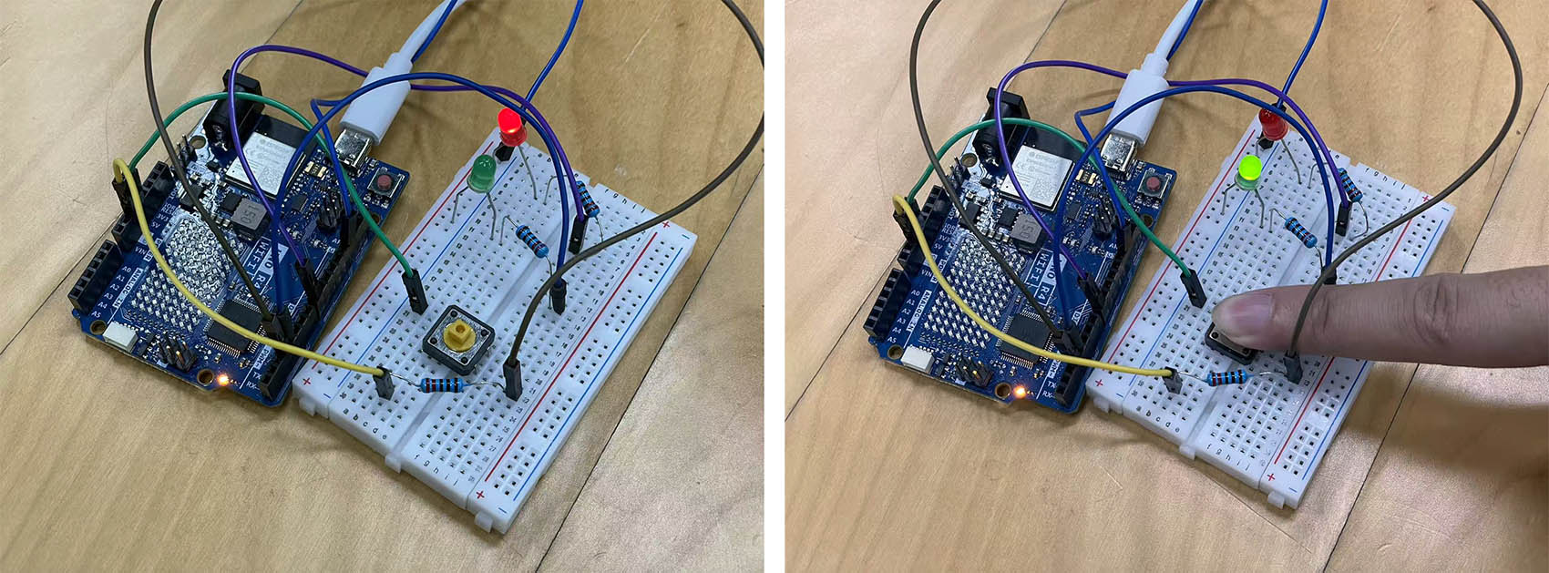
I then built the same Scenario 1 circuit on a breadboard and programmed the UNO R4 WiFi with the Arduino IDE 2.3.8:
- Step 1: Copy the code from Tinkercad into a new sketch, connect the board by USB-C and select the board: Arduino UNO R4 WiFi on COM3.
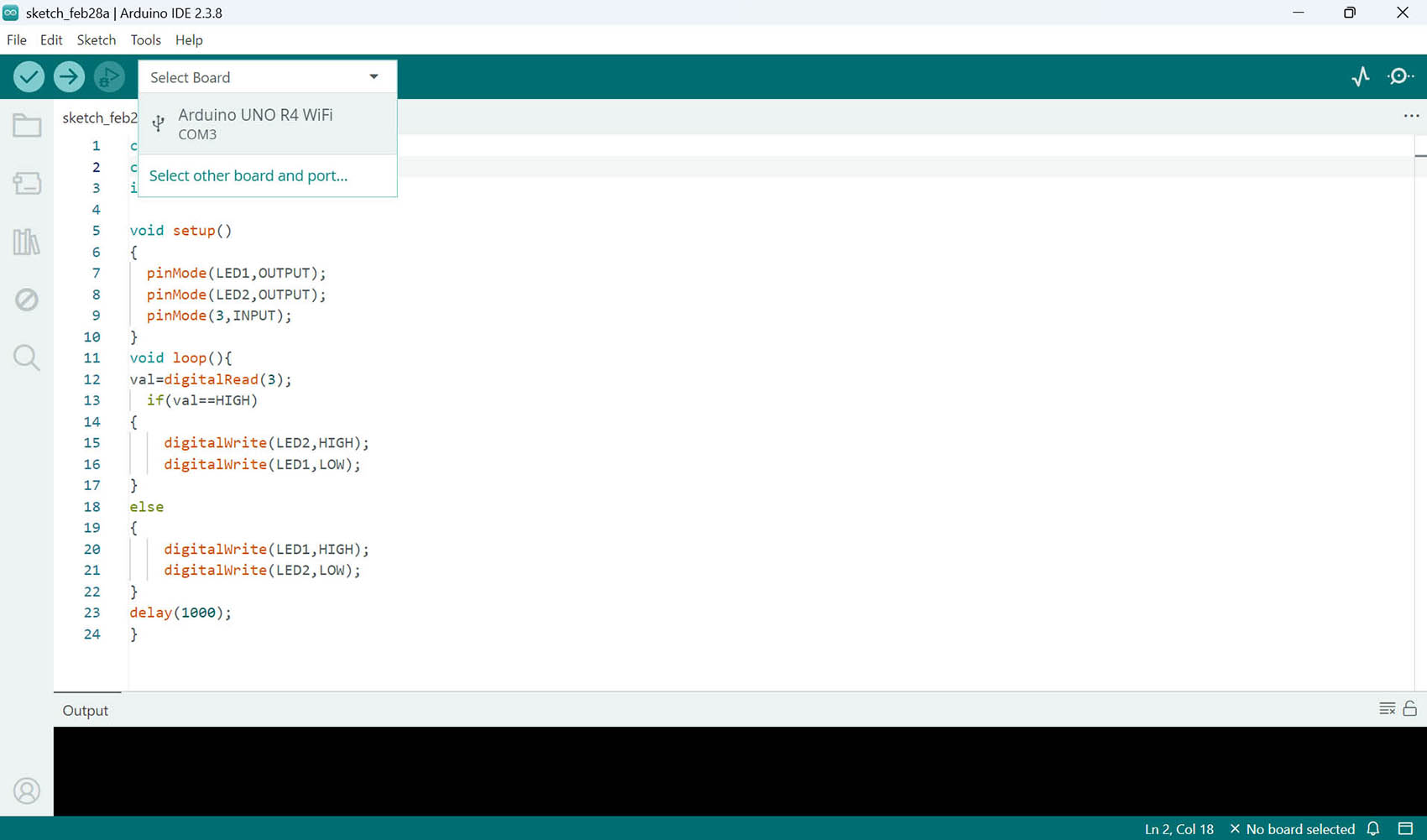
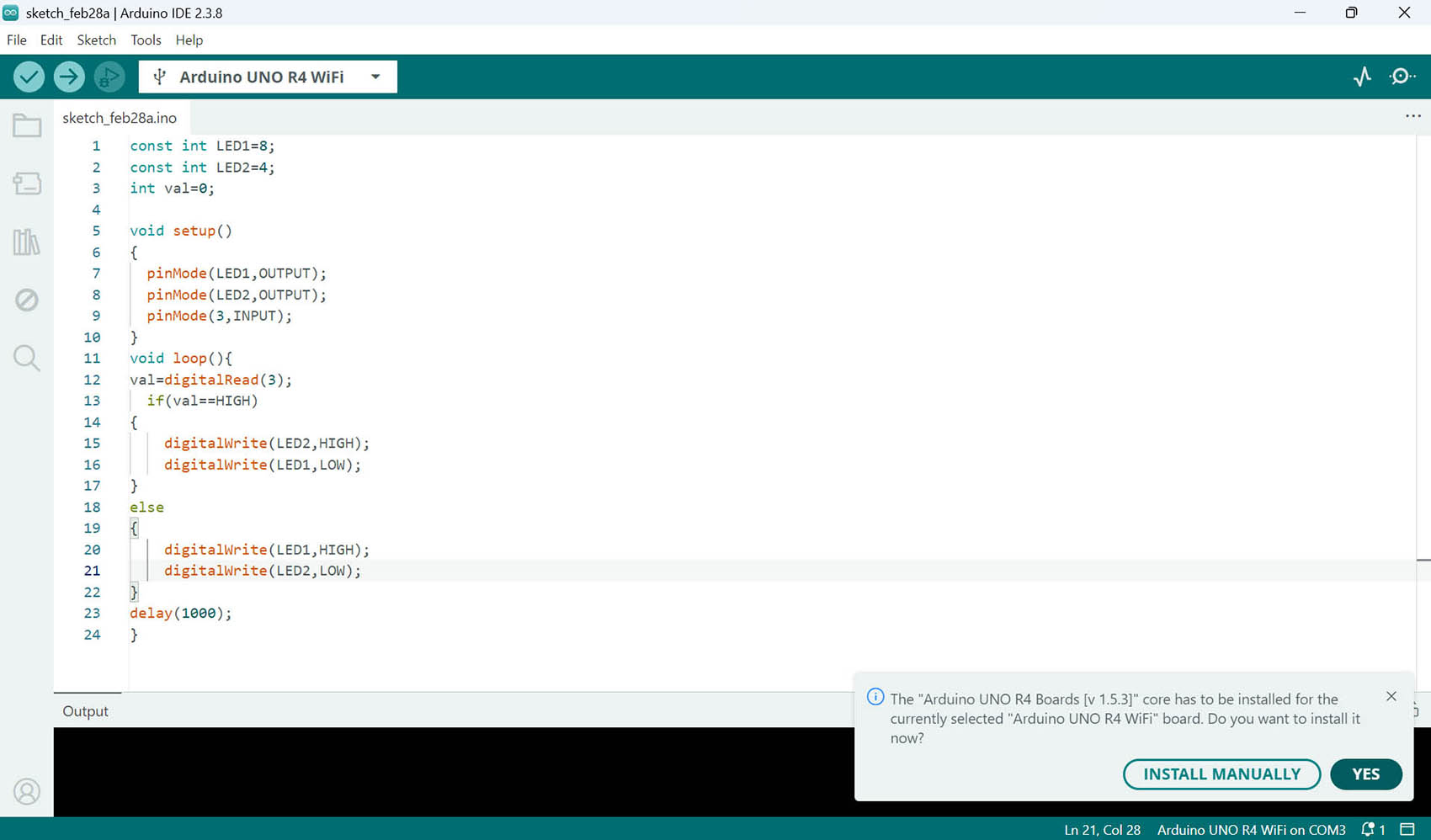
- Step 2: The IDE asked to install the "Arduino UNO R4 Boards" core (v1.5.3), which is needed for this board → I clicked Yes.
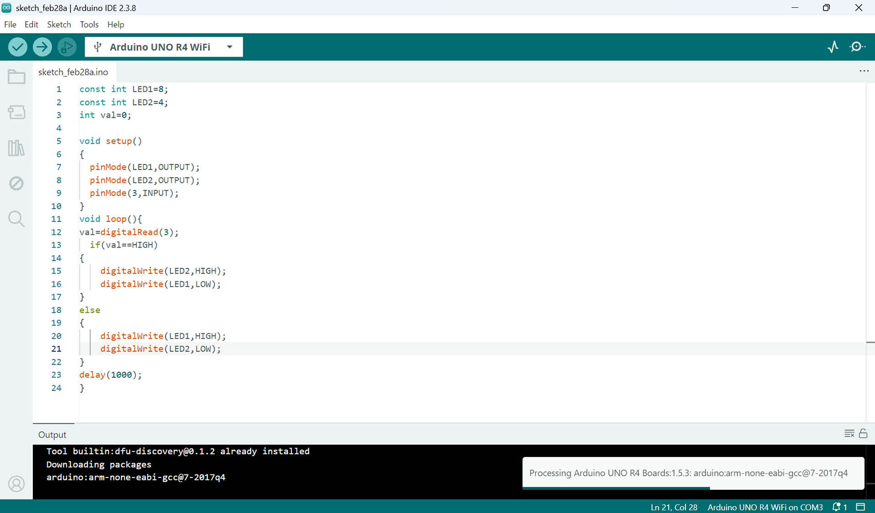
- Step 3: The IDE downloaded the core and the compiler toolchain (arm-none-eabi-gcc, because the RA4M1 is an Arm chip).
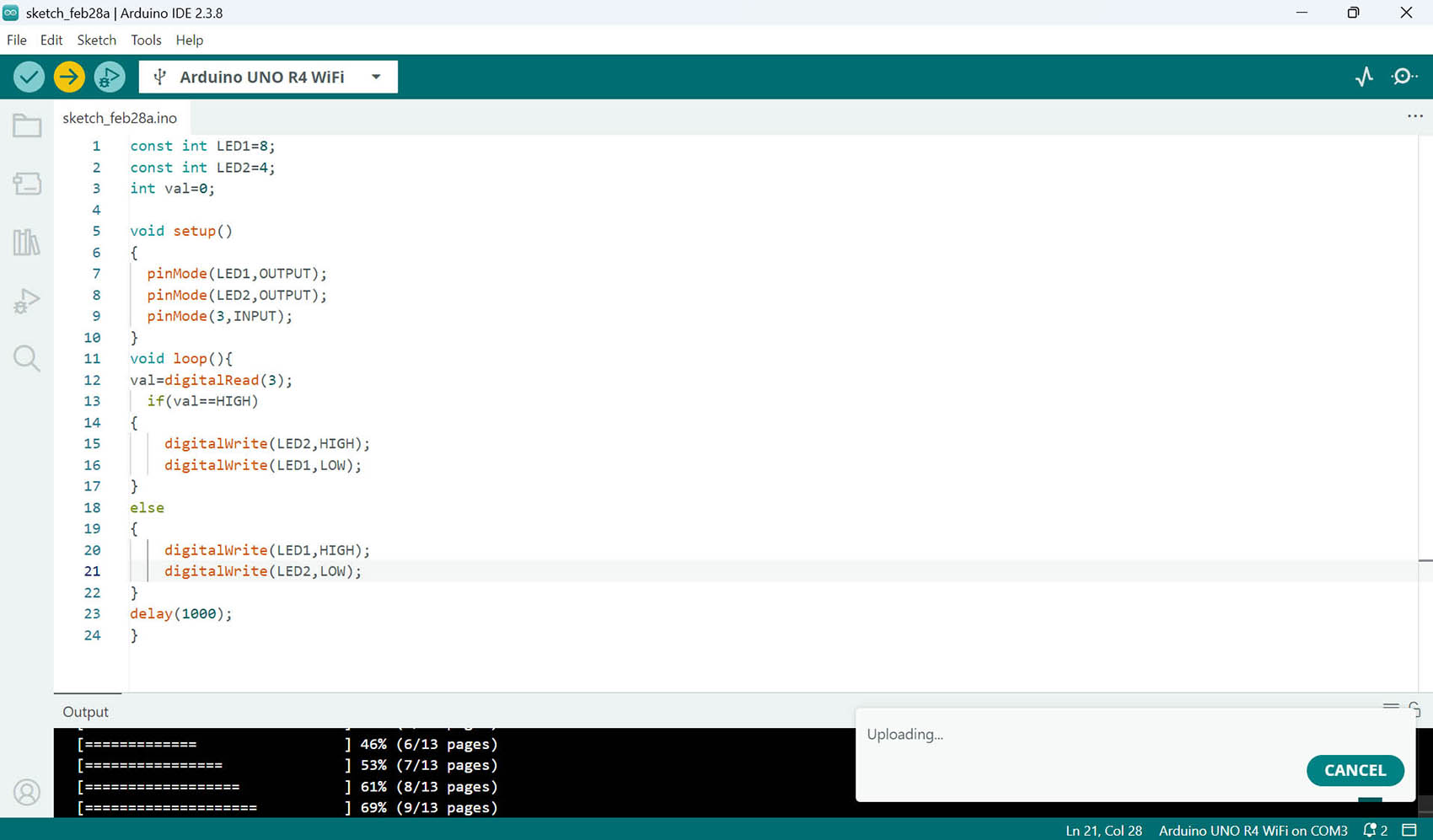
- Step 4: I clicked Upload: the IDE compiled the sketch and uploaded it to the board over USB.
Result:
The physical circuit behaves like the simulation: the red LED is on by default, and pressing the button switches to the green LED.
4. Communication: sending data over USB serial
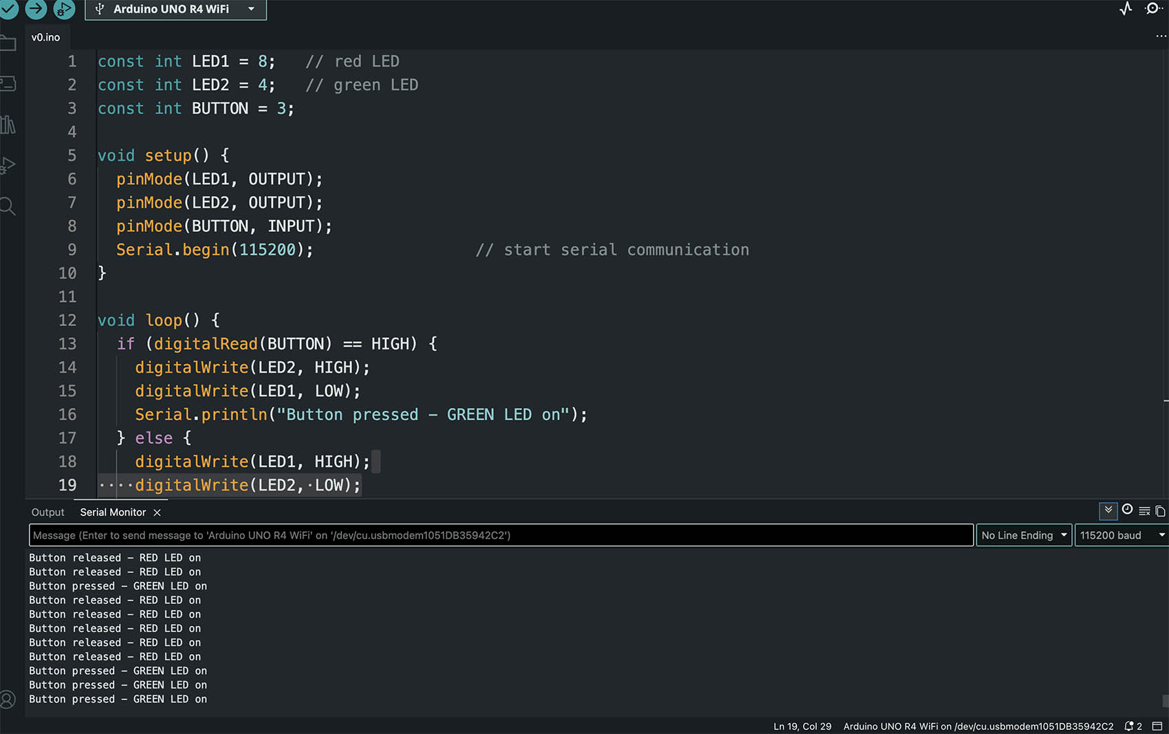
To meet the communication part of the assignment, I added serial communication to Scenario 1. The board sends the button state over the USB cable (a wired connection) to the Serial Monitor in the Arduino IDE, at 115200 baud.
const int LED1 = 8;   // red LED
const int LED2 = 4;   // green LED
const int BUTTON = 3;

void setup() {
  pinMode(LED1, OUTPUT);
  pinMode(LED2, OUTPUT);
  pinMode(BUTTON, INPUT);
  Serial.begin(115200);                 // start serial communication
}

void loop() {
  if (digitalRead(BUTTON) == HIGH) {
    digitalWrite(LED2, HIGH);
    digitalWrite(LED1, LOW);
    Serial.println("Button pressed - GREEN LED on");
  } else {
    digitalWrite(LED1, HIGH);
    digitalWrite(LED2, LOW);
    Serial.println("Button released - RED LED on");
  }
  delay(200);
}
Each time the loop runs, the board prints a line to the Serial Monitor, so I can see the button state on the computer while the LEDs change on the board.
5. Reflection
- Simulating in Tinkercad first let me check the wiring and the logic safely, before building the circuit for real.
- Moving to the UNO R4 WiFi needed only one extra step, installing the board core. The code itself stayed the same.
- The datasheet reminded me to check the current limit per pin and use a resistor with each LED.
- delay() is simple, but it blocks the program. With a long delay, the button feels slow to respond.